Trane BAYLOAM301 User manual

Type
User manual

Trane BAYLOAM301 is a rooftop unit designed for commercial and industrial applications, offering reliable and efficient climate control solutions. With capacities ranging from 15 to 25 tons, it is suitable for large spaces requiring precise temperature and humidity management. The unit's advanced features include a low ambient control that ensures optimal performance even in challenging weather conditions.

Trane BAYLOAM301 is a rooftop unit designed for commercial and industrial applications, offering reliable and efficient climate control solutions. With capacities ranging from 15 to 25 tons, it is suitable for large spaces requiring precise temperature and humidity management. The unit's advanced features include a low ambient control that ensures optimal performance even in challenging weather conditions.

SAFETY WARNING
Only qualified personnel should install and service the equipment. The installation,
starting up, and servicing of heating, ventilating, and air-conditioning equipment
can be hazardous and requires specific knowledge and training. Improperly
installed, adjusted or altered equipment by an unqualified person could result in
death or serious injury. When working on the equipment, observe all precautions
in the literature and on the tags, stickers, and labels that are attached to the
equipment.
132
4 5 6 7
©2022
Installation Instructions
Low Ambient Control
Foundation™ Packaged Rooftop Units
3-Phase, 15 to 25 Tons
Model Number: Used With:
BAYLOAM301* E/GCC180-300 (except E/GCC300 - 240V)
BAYLOAM302* E/GCC300 (240V)
Warnings, Cautions, and Notices
Read this manual thoroughly before operating or servicing this unit. Safety
advisories appear throughout this manual as required. Your personal safety and
the proper operation of this machine depend upon the strict observance of these
precautions.
Important Environmental Concerns
Scientific research has shown that certain man-made chemicals can affect the
earth’s naturally occurring stratospheric ozone layer when released to the
atmosphere. In particular, several of the identified chemicals that may affect the
ozone layer are refrigerants that contain Chlorine, Fluorine and Carbon (CFCs)
and those containing Hydrogen, Chlorine, Fluorine and Carbon (HCFCs). Not all
refrigerants containing these compounds have the same potential impact to the
environment. Trane advocates the responsible handling of all refrigerants-
including industry replacements for CFCs such as HCFCs and HFCs.
Important Responsible Refrigerant Practices
Trane believes that responsible refrigerant practices are important to the
environment, our customers, and the air conditioning industry. All technicians
who handle refrigerants must be certified according to local rules. For the USA,
the Federal Clean Air Act (Section 608) sets forth the requirements for handling,
reclaiming, recovering and recycling of certain refrigerants and the equipment
that is used in these service procedures. In addition, some states or
municipalities may have additional requirements that must also be adhered to for
responsible management of refrigerants. Know the applicable laws and follow
them.
The three types of advisories are defined as follows:
WARNING Indicates a potentially hazardous situation which, if
not avoided, could result in death or serious injury.
CAUTION Indicates a potentially hazardous situation which, if
not avoided, could result in minor or moderate injury.
It could also be used to alert against unsafe practices.
NOTICE Indicates a situation that could result in equipment or
property-damage only accidents.
WARNING
Proper Field Wiring and Grounding Required!
Failure to follow code could result in death or serious injury. All field wiring
MUST be performed by qualified personnel. Improperly installed and grounded
field wiring poses FIRE and ELECTROCUTION hazards. To avoid these
hazards, you MUST follow requirements for field wiring installation and
grounding as described in NEC and your local/state/national electrical codes.
WARNING
Personal Protective Equipment (PPE) Required!
Failure to wear proper PPE for the job being undertaken could result in death
or serious injury. Technicians, in order to protect themselves from potential
electrical, mechanical, and chemical hazards, MUST follow precautions in this
manual and on the tags, stickers, and labels, as well as the instructions below:
Before installing/servicing this unit, technicians MUST put on all PPE
required for the work being undertaken (Examples; cut resistant
gloves/sleeves, butyl gloves, safety glasses, hard hat/bump cap, fall
protection, electrical PPE and arc flash clothing). ALWAYS refer to
appropriate Safety Data Sheets (SDS) and OSHA guidelines for proper PPE.
When working with or around hazardous chemicals, ALWAYS refer to the
appropriate SDS and OSHA/GHS (Global Harmonized System of
Classification and Labeling of Chemicals) guidelines for information on
allowable personal exposure levels, proper respiratory protection and
handling instructions.
If there is a risk of energized electrical contact, arc, or flash, technicians
MUST put on all PPE in accordance with OSHA, NFPA 70E, or other country-
specific requirements for arc flash protection, PRIOR to servicing the unit.
NEVER PERFORM ANY SWITCHING, DISCONNECTING, OR VOLTAGE
TESTING WITHOUT PROPER ELECTRICAL PPE AND ARC FLASH
CLOTHING. ENSURE ELECTRICAL METERS AND EQUIPMENT ARE
PROPERLY RATED FOR INTENDED VOLTAGE.
Copyright
This document and the information in it are the property of Trane, and may not
be used or reproduced in whole or in part without written permission. Trane
reserves the right to revise this publication at any time, and to make changes to
its content without obligation to notify any person of such revision or change.
Trademarks
All trademarks referenced in this document are the trademarks of their respective
owners.
Revision History
Model number updates in Used With information.
Inspection
Remove the contents of the kit from the shipping package and inspect for
possible damage. If any damage is found, report it immediately, and file a claim
against the transportation company. Any missing parts should be immediately
reported to your supplier and replaced with authorized parts only.
WARNING
Follow EHS Policies!
Failure to follow instructions below could result in death or serious injury.
All Trane personnel must follow the company’s Environmental, Health and
Safety (EHS) policies when performing work such as hot work, electrical, fall
protection, lockout/tagout, refrigerant handling, etc. Where local
regulations are more stringent than these policies, those regulations
supersede these policies.
Non-Trane personnel should always follow local regulations.
Parts List
Installation
Table 1. Parts list
Qty Description
1 Speed Controller
1 Temperature Sensor
1 Pressure Tap
2Screws
5 Wire Harnesses
1 Pressure Transducer
13 Wire Ties
1Grommet
1 Gasket
1 Airflow Sleeve
1 Installers Guide
1 Installed Accessory Label
2 Motors (only in Kit BAYLOAM302**)
2 Fans (only in Kit BAYLOAM302**)
Table 2. Electrical, temperature and pressure ratings
Volts, AC 208, 240, 380, 415, 480, 600
Control Voltage 18-30 VAC
Frequency 50-60 Hz
Operating Temperature -40ºF + 140ºF (-40ºC to 60ºC)
Full Load Amps 10 Amps
Transducer Pressure Control Range 0-500 psi
Controller
1. Prepare the unit for installation.
a. Disconnect all power from the unit.
b. Remove the compressor and control box access panel(s).
2. Refer to Figure 1 and Figure 2 to determine the mounting location and
position of the controller inside the control box.
3. Mount the controller in the appropriate position using two screws. If airflow
sleeve is not installed, install it with the gasket using two screws as shown in
Figure 3. If airflow sleeve is installed then proceed to next step.
4. Install temperature sensor in airflow sleeve with grommet provided, as shown
in Figure 3.
WARNING
Hazardous Voltage!
Failure to disconnect power before servicing could result in death or serious
injury.
Disconnect all electric power, including remote disconnects before servicing.
Follow proper lockout/tagout procedures to ensure the power can not be
inadvertently energized. Verify that no power is present with a voltmeter.
Figure 1. Low ambient controller location in control box - CV units
Figure 2. Low ambient controller location in control box - VFD units
Figure 3. Airflow sleeve and sensor location
Temperature
Sensor
Gasket
Airow
Sleeve
Transducer and Tee
1. Remove cap nut from the unit high pressure service port on the discharge
lines that run from each compressor. See Figure 4.
2. Install the transducer onto the tee port. See Figure 5.
3. Place the tee flare nut with valve core depressor on the unit high pressure tap,
where the cap nut was located.
4. Tighten flare nut securely to the high pressure service port and check for
leaks.
5. Ensure that the transducer and tee do not come into contact with the access
panel.
Figure 4. High pressure service port
Figure 5. Transducer to tee
High Pressure
Service Port
December 2022 ACC-SVN210D-EN
91110
12 13 14 15
8
©2022
Trane and American Standard have a policy of continuous product and product data improvement and reserve the
right to change design and specifications without notice. We are committed to using environmentally conscious print
practices.
Trane and American Standard create comfortable, energy efficient indoor environments for commercial
and residential applications. For more information, please visit trane.com or americanstandardair.com.
Outdoor Motor change (only for BAYLOAM302*)
Figure 6. Tee and transducer installed on high pressure service port
WARNING
Hazardous Voltage!
Failure to disconnect power before servicing could result in death or serious
injury.
Disconnect all electric power, including remote disconnects before servicing.
Follow proper lockout/tagout procedures to ensure the power can not be
inadvertently energized. Verify that no power is present with a voltmeter. 1. Confirm all power to the unit has been disconnected and locked out.
2. The power harness connector must be disconnected from the terminal plug
on the motor, prior to removing motor.
3. Remove the fan tightening screw and slide the fan out.
Figure 7. Tee and transducer installed on high pressure service port
WARNING
Risk of Motor Falling!
Motor is mounted in such a position that it could fall when bolts are removed. To
avoid possible injury, the motor should be supported prior to removing the bolts.
Tightening screw Fan Motor
Motor mounting nut and bolt
Tightening screw
Terminal plug
Stops on shell
Bellyband
4. Loosen the motor securing nut and bolt from bellyband and slide the motor
out.
5. Replace the motor with the one from kit.
6. While tightening the bolt, confirm the stops on the motor shell are resting on
the top edge of bellyband (in all four positions – 90 degree from center of
terminal plug), and the terminal plug is opposite to the mounting bolt.
7. The bolt and nut assembly, (holding the bands around motor) shall be torqued
to 100 - 120 in-lb.
8. Assemble the fan on the motor shaft with a fan tightening screw while
maintaining a 3 inch distance from top cover to top of fan hub.
Note: Fan hub to shaft set screw to be torqued to 130 - 150 in-lb.
Important: Dimension from bottom of grille to the highest point of fan blade shall
not be less than one inch.
9. Use a tool to rotate fan manually to check for minimum clearance of 0.12
inches between fan and orifice.
10.Connect the power harness female connector to the terminal plug on the
motor.
NOTICE
Equipment Damage!
Failure to follow instructions below could result in equipment damage.
Proper alignment of the motor is important to ensure optimal unit operation.
Improper alignment, over tightening or under tightening the can result in motor
slippage, fan misalignment, bearing damage and possible failure of fan motor
mounts.
WARNING
Rotating Components!
Failure to disconnect power before servicing could result in rotating components
cutting and slashing technician which could result in death or serious injury.
During installation, testing, servicing and troubleshooting of this product it may
be necessary to work with live and exposed rotating components. Have a
qualified or licensed service individual who has been properly trained in
handling exposed rotating components, perform these tasks.
11.Repeat the process for the second condenser motor and fan in the unit.
Control Box Wiring
1. Following the unit schematic, make all indicated connections in unit control
box. See unit schematic located on compressor access panel.
a. Remove the existing harness connected from the ODM contactors to the
PPM30 connector in the control panel.
b. Install harness parts 438726240001, 438727960001 and
438729830001 for non-VFD units. Install harness parts 438726240001,
438727960002 and 438729830002 for VFD units. Refer to Figure 1 and
Figure 2 to route the harnesses inside the control box.
c. Connect the leads from the temperature sensor to the harness part
438726240001 and the leads from the pressure transducer to the
controller. Cut wire ties, if necessary, to properly route wires.
2. Finish wiring installation:
a. Using wire ties, bundle and dress any excess wires.
b. After the settings have been properly adjusted (see “Controller
Operation”), reinstall the compressor and control box access panels and
secure with screws that were removed.
c. Re-connect all power to the unit. Refer to “Troubleshooting” section,
Table 3, if needed.
Controller Settings
For non-heat pump applications, the heat pump select jumper must be in the
Default (N.O.) position, and the HP terminals must be left unconnected.
WARNING
Hazardous Voltage!
Failure to disconnect power before servicing could result in death or serious
injury.
Disconnect all electric power, including remote disconnects before servicing.
Follow proper lockout/tagout procedures to ensure the power can not be
inadvertently energized. Verify that no power is present with a voltmeter.
Controller Operation
This electronic control will be used on an air conditioner system to reach and
maintain head pressure within an acceptable range when ambient temperature
falls below 50°F. It reads discharge pressure from a pressure transducer and
accordingly turns on and off the outdoor fan motor to maintain discharge pressure
at the selected set point.
For Constant Volume Units
Outdoor fan cycling will occur when the ambient temperature is below 50°F. Both
outdoor fans will energize and cycle at the same time. Above 50ºF, the outdoor
fans will energize at the same time without cycling.
For Units Equipped with an Optional VFD
The outdoor fans are staged based on outdoor ambient temperature. In ambient
temperatures below 50ºF, only 1 fan will energize and cycle. When the ambient
temperature reaches above 50ºF, the controller will no longer cycle outdoor fans.
The unit will stage the outdoor fans based on the unit temperature sensor. For
ambients above 60ºF +/-5ºF, both outdoor fans should be energized. Below 60ºF
+/-5ºF, single fan operation is normal.
Setting the Pressure Setpoint
When using a pressure transducer, the control will maintain condenser pressure
between 15 psig above and 15 psig below dialed pressure setpoint.The dial
pressure setpoint range is 35 psig to 465 psig. The pressure setpoint should be
adjusted to 250 psig initially. Monitor the condenser discharge pressure and
adjust the pressure setpoint so the condenser fan operates at full speed when the
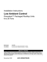
Figure 8. Jumper position
N.O.
ambient temperature is greater than 50°F and modulates speed when the
ambient temperature is below 50°F.
Note: There is no exact correlation between dial temperature and pressure
scales on the control.
Troubleshooting
Before leaving the installation, observe for correct operation through the
desired pressure range. See Table 3.
Figure 9. Pressure setpoins
Table 3. Troubleshooting guide
Problem Possible Cause Possible Solution
No fan
operation
No 24 volt control
voltage
Check for 24 VAC at control and verify correct wiring. If
wired correctly, check voltage across the transformer.
No line voltage Check voltage across the black, red, and blue OD motor
leads. If no line voltage is present, verify all wiring is
correct.
Improper fan
operation
Heat pump jumper not
configured correctly
Refer to the IOM or correct hook-up diagram and verify the
heat pump jumper is configured correctly.
Control is not wired
correctly
See wiring diagrams. Ensure that the 24 VAC power
supply is connected in-phase with the motor power
supply.
No fan
modulation
No need to modulate the
fan
If pressure is equal to or greater than the head pressure
control setpoint, the fan will be operating at full speed.
No input pressure to
control
Check for proper transducer and Tee installation.
Schrader valve depressor must depress Schrader valve
enough to allow refrigerant into pressure transducer.
Miswired Check that the 24 VAC signal and the transducer are
wired
up correctly into the controller.
Erratic fan
operation
Control is not wired
correctly
See wiring diagrams.
Pressure transducer
problem
Check for proper transducer and Tee installation.
Schrader valve depressor must depress Schrader valve
enough to allow refrigerant into pressure transducer.
Dirty or blocked
condenser coil
Clean condenser coil.
Fan motor
is cycling
on thermal
overload
Dirty or blocked
condenser coil
Clean condenser coil.
Wrong motor for fan
speed control
application. Verify new
motor was installed.
Replace with motor
Verify new motor was installed. Replace with motor
approved for fan speed control application.
Unit fails to
start
Incorrect/No voltage
present
Using an AC voltmeter, measure the voltage between the
24VAC terminals. It should read approximately 24 volts.
Measure line voltage between LINE1, LINE2 and LINE 3
to confirm that line voltage is present.
Transducer malfunction
or not installed
If lights are flashing alternatively, then no probe is
connected or the probe is malfunctioning. When using a
pressure transducer, with power applied to the control,
use a voltmeter to measure volts DC between COMM and
P1 or P2, where the wire is connected. The reading should
be according to Table 3 below.
Table 3. Troubleshooting guide (continued)
Problem Possible Cause Possible Solution
Table 4. Pressure vs. voltage
Pressure (psig) Voltage (Vdc)
00.5
50 0.9
100 1.3
150 1.7
200 2.1
250 2.5
300 2.9
350 3.3
400 3.7
450 4.1
500 4.5
ACC-SVN210D-EN 03 Dec 2022
Supersedes ACC-SVN210C-EN (Nov 2020)
  • Page 1 1
  • Page 2 2

Trane BAYLOAM301 User manual

Type
User manual

Trane BAYLOAM301 is a rooftop unit designed for commercial and industrial applications, offering reliable and efficient climate control solutions. With capacities ranging from 15 to 25 tons, it is suitable for large spaces requiring precise temperature and humidity management. The unit's advanced features include a low ambient control that ensures optimal performance even in challenging weather conditions.

Ask a question and I''ll find the answer in the document

Finding information in a document is now easier with AI