Page is loading ...

DANGER
HAZARD OF FIRE, ELECTRIC SHOCK, EXPLOSION, OR ARC FLASH
This Freedom e-GEN System Installation Guide with Freedom SW for OEM Installers is in addition to, and incorporates by reference, the relevant
product manuals for each product in the power system. After reviewing this guide you must read the relevant product manuals. Unless specified,
information on safety, specifications, installation, and operation is as shown in the primary documentation received with the product. Ensure you
are familiar with that information before proceeding.
Failure to followthese instructions willresult in death orseriousinjury.
Exclusion for Documentation
UNLESS SPECIFICALLY AGREED TO IN WRITING, SELLER (A) MAKES NO WARRANTY AS TO THE ACCURACY, SUFFICIENCY OR
SUITABILITY OF ANY TECHNICAL OR OTHER INFORMATION PROVIDED IN ITS MANUALS OR OTHER DOCUMENTATION; (B)
ASSUMES NO RESPONSIBILITY OR LIABILITY FOR LOSSES, DAMAGES, COSTS OR EXPENSES, WHETHER SPECIAL, DIRECT,
INDIRECT, CONSEQUENTIAL OR INCIDENTAL, WHICH MIGHT ARISE OUT OF THE USE OF SUCH INFORMATION. THE USE OF ANY
SUCH INFORMATION WILL BE ENTIRELY AT THE USER’S RISK; AND (C) REMINDS YOU THAT IF THIS MANUAL IS IN ANY
LANGUAGE OTHER THAN ENGLISH, ALTHOUGH STEPS HAVE BEEN TAKEN TO MAINTAIN THE ACCURACY OF THE TRANSLATION,
THE ACCURACY CANNOT BE GUARANTEED. APPROVED CONTENT IS CONTAINED WITH THE ENGLISH LANGUAGE VERSION
WHICH IS POSTED AT HTTP://WWW.XANTREX.COM.
NOTE:Visit http://www.xantrex.com , click Products, select a Product category, select a Product, and search the Product Documents panel for a
translation of the English guide, if available.
Contact Information
Telephone: +1-800-670-0707 / +1-408-987-6030
Email: customerservice@xantrex.com,
http://www.xantrex.com/power-products-support/
Web: http://www.xantrex.com
1
Important Safety Information
READ AND SAVE THESE INSTRUCTIONS
Electrical equipment shall be installed, operated, serviced, and maintained only by qualified personnel.
Certain configuration tasks shall only be performed by qualified personnel in consultation with your local
utility and/or an authorized dealer. Servicing of batteries and the BMS shall only be performed or supervised
by qualified personnel with knowledge of lithium-ion batteries and their required precautions. Qualified
personnel have training, knowledge, and experience in:
• Installing electrical equipment
• Applying applicable installation codes
• Analyzing and reducing the hazards involved in performing electrical work
• Installing and configuring lithium-ion batteries
• Selecting and using Personal Protective Equipment (PPE)
No responsibility is assumed by Xantrex LLC for any consequences arising out of the use of this material.
DANGER
HAZARD OF FIRE, ELECTRIC SHOCK, EXPLOSION, OR ARC FLASH
• Apply appropriate personal protective equipment (PPE) and follow safe electrical work practices. See
NFPA 70E or CSA Z462.
• Equipment shall only be installed and serviced by qualified electrical personnel.
• Never operate equipment energized with covers removed.
• Inverters are energized from multiple sources. Before removing covers of inverters and other equipment,
identify all sources, de-energize, lock-out and tag-out, and wait 2 minutes for circuits to discharge.
• Always use a properly rated voltage sensing device to confirm all circuits are de-energized.
Failure to follow these instructions will result in death or serious injury.
Battery Safety Information
DANGER
ARC FLASH
HAZARD
An arc flash is the light and heat produced from an electric arc supplied with sufficient electrical
energy to cause substantial damage, harm, fire, or injury.
An example of an arc flash event could be a direct short circuit caused by a metallic object such as a
tool bridging between the positive and negative of an energized circuit.
Refer to section 6 for Arc Flash Energy Specifications
DANGER
HAZARD OF FIRE, ELECTRIC SHOCK, EXPLOSION, OR ARC FLASH
• Do not expose the Xantrex Battery to rain, snow, or liquid of any type. This battery pack is not suitable for
marine applications.
• The Xantrex Battery must be used with the Xantrex Battery Management System (BMS).
• Always wear proper PPE (safety glass and clothing) when working on the Xantrex Battery.
• Do not wear metallic items such as watches or bracelets when working on the battery. Use insulated tools
to prevent accidental short circuit.
• Do not short-circuit the battery.
• Do not expose the battery to flames.
• Do not step on the battery.
• Do not attempt to open or dismantle the Xantrex Battery. If the battery is damaged, do not touch the
corrosive electrolyte or powder. In case battery content comes in contact with skin or eyes, immediately
flush the affected area with large amount of clean water and seek medical help.
• When the battery is damaged, it can release harmful gases. Ensure the work environment is well-
ventilated.
• In case of fire, use only a Class ABC type (dry chemical) fire extinguisher. Water can be a dangerous
extinguishing medium for energized equipment because of the risk of electrical shock.
• Dispose of Xantrex Batteries through a local recycling center. Do not mix batteries with other wastes.
Contact your local recycling center for proper disposal information.
Failure to follow these instructions will result in death or serious injury.
WARNING
RISK OF PERSONAL INJURY OR EQUIPMENT DAMAGE
• The Xantrex Battery must be mounted upright on a horizontal plane. Always follow the manufacturer’s
mounting instructions.
• Make sure the Xantrex Battery is fastened and secured. The battery is heavy and can become a crush
hazard if not secured properly.
• Do not install the Xantrex Battery under the engine hood or in an environment where the ambient
temperature exceeds 113°F(45°C).
• You must install and use the required battery disconnect, fuses and fuseholders. Replace expended
fuses with fuses of the same specifications.
• Do not use stainless lugs on the BMS terminals or on any high-current terminals.
• Always use proper lifting techniques when handling the Xantrex Battery.
Failure to followthese instructions can result in personal injuryand/ordamageto equipment and may void the
warranty.
System Safety Information
WARNING
HAZARD OF ELECTRIC SHOCK, FIRE, OR PERSONAL INJURY
• Do not expose any of the equipment to rain, snow, or liquids of any type. Products in the system are
designed for indoor use only.
• Do not obstruct the air ventilation openings on the system devices. Do not install or operate any of the
system devices in compartment containing flammable materials or in locations that require ignition-
protected equipment.
• Make sure that existing wiring is in good condition and that wires/cables are not undersized.
• Make sure that all DC and AC connections are properly tightened (to the correct torque specified by the
manufacturer) and secured.
• Do not operate the inverter and other equipment with damaged or substandard wiring.
• Equipment such as the inverter must be provided with an equipment-grounding conductor connected to
the AC input ground as well as a DC enclosure grounding conductor connecting the inverter chassis to
the vehicle chassis.
Failure to follow these instructions can result in death or serious injury.
WARNING
HAZARD OF ELECTRIC SHOCK, FIRE, OR PERSONAL INJURY
• Install means of disconnection from all power sources, such as, AC and DC circuit breakers.
• Make sure that terminal covers are installed and there are no exposed conductors.
• Make sure the second alternator’s temperature sensor is properly installed.
Failure to follow these instructions can result in death or serious injury.
CAUTION
RISK OF PERSONAL INJURY OR EQUIPMENT DAMAGE
• Use the right tools for the job. Use of improper tools may result in damage to equipment and personal
injury.
• Verify the weight-bearing capacities of the compartments where the system devices will be mounted and
installed.
• Do not lift heavy equipment by yourself. Use two or more people to lift and mount heavy equipment such
as the inverter and battery. Use proper lifting techniques during installation to prevent injury and
equipment damage.
• Mount and fasten all devices securely according to their installation guides.
Failure to follow these instructions can result in personal injury and/or damage to equipment
and may void the warranty.
NOTICE
RISK OF BATTERY DAMAGE
• Observe proper polarity.
• Observe proper storage technique. Store the battery within the temperature and humidity specified by
the manufacturer.
Failure to followthese instructions can result in damageto battery andmay void thewarranty.
.
2
Introduction
The Freedom e-GEN System Installation Guide with Freedom SW for OEM Installers
provides a system overview and installation instructions of a complete power solution that
includes:
la Freedom SW 3012 Inverter/Charger for power conversion,
la Conext ComBox for Freedom SW and Tablet* for monitoring,
la vehicle’s second alternator and regulator kit as a power source, and
la Xantrex Battery with Xantrex BMS for energy storage
This system installation guide is intended to be used by qualified installers. This document
provides you as much detail as possible to guide you through the installation process;
however, this is not a comprehensive, all-in-one guide. You must read the relevant product
manuals that come with each of the system devices and understand the information in
those manuals about safety, specification, installation and operation.
It is the installer's responsibility to ensure the installation is carried out in a safe manner
and the end-installation is compliant to applicable code standards.
*Some systems may come with a System Control Panel (SCP)
975-0790-01-01 Rev J
Dec 2020
Copyright © 2019-2020 Xantrex LLC. All Rights Reserved.
All trademarks are owned by Xantrex LLC and its affiliates.
1
Freedom e-GEN System Installation Guide with Freedom SW for OEM Installers
http://www.xantrex.com

Freedom e-GEN System Installation Guide for OEM Installers http://www.xantrex.com
2Copyright © 2019-2020 Xantrex LLC. All Rights Reserved.
All trademarks are owned by Xantrex LLC and its affiliates.
975-0790-01-01 Rev J
Dec 2020
4. Mount and install the DC wiring components including the battery disconnect switch
(if applicable), fuseholders, and the busbars. Their relative locations are shown in the
system diagram. The battery disconnect switch and the fuseholder for the main
battery fuse should be located as close to the BMS positive terminal as possible. If
applicable, install the fuseholder for the DC load branch fuse on the positive cable
close to the positive DC busbar.
5. Mount and install the second alternator using the tools and instructions provided in
the alternator kit. Follow the steps below as a guide but refer to the manufacturer’s
instructions for complete detail.
a. Install the second alternator using the mounting bracket and pulley provided in
the alternator kit.
b. Ensure the alternator chassis is securely fastened to the vehicle metal chassis.
c. Use a straight edge or laser alignment tool to ensure pulleys are within 0.5
degrees of alignment.
d. Check all pulley grooves to ensure they are clean and undamaged. Check the
belt to make sure there are no visible cracks, splits, or defects before installing
it.
e. Install the belt. Ensure the belt is properly seated in the pulley grooves.
f. Check the belt tension between the engine and second alternator according to
the manufacturer’s recommendations. Adjust accordingly using the provided
tensioner and a tension gauge. Under or over-tensioned belt will cause belt
slippage and premature belt failure. It can also result in overheating of the
alternator leading to equipment damage.
5. g. Check that the Balmar Regulator has the “LFP” sticker before mounting. Contact
Xantrex if the “LFP” sticker is missing.
h. Mount the Balmar Regulator.
i. Follow the second alternator manufacturer's wiring instructions and use the
wiring harness in the alternator kit to make the connections between the second
alternator and the Balmar Regulator.
j. Make sure the alternator temperature sensor in the wiring harness is installed
on the second alternator’s chassis and connected to the correct pins on the
Balmar Regulator to prevent equipment damage and fire.
k. Make DC cable connections at the alternator. Refer to “DC Cable and Fuse
Requirements” for conductor sizing. Use a separate cable for alternator
negative return to the battery. Ensure all electrical connections are secured. To
protect from dust and water, install a skid plate (not provided but
recommended).
6. Read “DC Cable and Fuse Requirements”. Then, make the DC cable connections
between all system devices by following the “System Diagram for Power Connection”.
Observe correct polarity.
7. Install the required DC fuses on to their respective fuseholders.
8. If applicable, install a venting tube (rubber tubing) to the pressure balancing valve on
the battery and secure it with a clamp.
9. Make AC wiring connections to the Freedom SW according to the “System Diagram
for Power Connection”. Follow the Freedom SW installation guide (document number:
97-0020-01-01) for AC wire sizing instructions.
a. Wire the GFCI kit to the Freedom SW AC INPUT according to the “System
Diagram for Power Connection”. You must wire to the line side of the GFCI
through the 15A supplementary breaker. Use proper wire-splicing technique
and ensure the wire joints are secured and covered with electrical tape.
b. Wire the Freedom SW AC OUTPUT to your AC load panel.
c. Install the GFCI kit to cover the Freedom SW AC terminal.
d. Ensure that all upstream and downstream surge protector and AC circuit
breakers are properly installed. Refer to the Freedom SW installation guide for
breaker sizes.
e. Locate the AC adapter provided in the system wiring harness. Plug it to one of
the two AC receptacles on the GFCI.
3
System Devices
Device Name Part Number
Freedom SW 3012 815-3012
Ford Transit Alternator Kit (option 1) 882-0050-12
Sprinter 6-cylinder Alternator Kit (option 2) 882-0010-12
Sprinter 4-cylinder Alternator Kit (option 3) 882-0020-012
Dodge Promaster Alternator Kit (option 4) 882-0030-12
Xantrex Battery 12V 600Ah (option 1) 880-0600-12
Xantrex Battery 12V 450Ah (option 2) 880-0450-12
Xantrex Battery 12V 630Ah (option 3) 880-0630-12
Xantrex Battery Management System 881-0406-12
Battery Disconnect Switch (12VDC, 450A min) --
Use one of UL-listed fuses
--Class T fuse rated 350A, 125VDC
--Class J fuse rated 400A, 450VDC
--Class J fuse rated 450A, 450VDC
cUse of other fuses and
fuseholders voids the UL
listing of the system.
NOTE:Class J fuses are
only permitted with the
12V630Ah battery
Fuse holder must be UL Listed (IZLT), suitable for single-pole, Type J
or Type T fuses, rated 600V, 450A
System Wiring Harness 881-0040-12
GFCI Kit 808-9003
Table 1 Required eGEN system devices and components Device Name Part Number
ComBox for Freedom SW 809-0918
Skid Plate for the second alternator --
100A fuse, Littelfuse [Required if the system includes the
Xantrex Battery Combiner (PN:881-0030-12)] MEG100
600A Busbars,1 for pos(+) and 1 for neg(-), Blue Sea 2104
Busbar cover, Blue Sea 2708
Xantrex Battery Combiner 881-0030-12
12A Temperature Sensor Switch
Heating Blanket, eGEN 135W (sold together) 881-0240-12
881-0060-12
100W Xantrex Solar Kit /100WExpansion Kit 780-0100-01 /780-0100-02
160W Xantrex Solar Kit /160WExpansion Kit 780-0160-01 /780-0160-02
110W Xantrex Solar Flex Kit /110WExpansion Kit 781-0100-01 /781-0100-02
Xantrex Solar 30A PWM Charge Controller 709-3024-01
Xantrex Solar 30A MPPTCharge Controller 710-3024-01
Android tablet 808-0016
Internet Modem/router 881-0050-12
System Remote Panel including LCD Display 881-0401-12
Freedom SW Remote Panel 808-9002
Router Power Harness 881-0020-12
Xanbus cable (50 ft.) 809-0941
Table 2Recommended eGEN system devices and components
4
Installation
WARNING
HAZARD OF ELECTRIC SHOCK, FIRE, OR PERSONAL INJURY
Read the system installation guide and associated product manuals prior to installation.
Failure to follow these instructions can result in death or serious injury.
1. Prior to installation, identify and isolate all energy sources from the system. De-
energize the system by:
a. removing AC power
b. turning off vehicle ignition
c. turning off the BMS
Keep the system de-energed throughout the installation process.
Follow all necessary safety precautions, use personal protective equipment (PPE) and
perform lock-out, tag-out (LOTO).
2. Plan the mounting locations for all the devices and wiring components prior to wiring.
Follow the mounting instructions for each device, verify the weight-bearing capacity of
each mounting location and orientation, and ensure sufficient clearance for proper air
ventilation.
3. Mount and install the system devices before making cable or wiring connections.
Secure heavy objects such as the inverter and the battery by bolting/strapping them to
the floor.

http://www.xantrex.com Freedom e-GEN System Installation Guide for OEM Installers
975-0790-01-01 Rev J
Dec 2020
Copyright © 2019-2020 Xantrex LLC. All Rights Reserved.
All trademarks are owned by Xantrex LLC and its affiliates.
3
lUse DC cables with a higher insulation temperature rating (105°C) if possible.
However, a higher insulation temperature rating does not mean the conductor size
can be reduced due to the temperature ratings of the terminal connections. Always
use a qualified installer to ensure conductor sizing complies with regional, national,
and local electrical codes.
lThe DC cables must be UL marked and certified.
lLonger cables may cause excessive voltage drop and affect system performance.
Keep cable length as short as practically possible.
lUse twin wires [pos(+) and neg(-) DC cables] for all DC connections. Do not use the
vehicle chassis in place of the DC negative connection. The system requires reliable
DC return paths.
lThe battery system must be used with a Xantrex-approved fuse (see Table 1 for a list
of approved fuse options). The main battery fuse and all other fuses in the system
must be installed on the positive (ungrounded) conductor as close to their power
sources as possible. Distance restrictions may apply according to applicable codes.
lThe DC load branch, if installed, must be properly fused. The total DC load branch
should not exceed 30A to avoid overheating the main DC cables and blowing the
main battery fuse. It is the installer's responsibility to ensure the voltage, current and
interrupt ratings of the DC load branch fuse are adequate to protect the cables and
downstream loads according to applicable codes.
lUse Xantrex-approved busbars (Blue Sea, 2104) to make the DC interconnections to
ensure sufficient current-carrying capacity. You must follow the connection order at
the busbar terminal studs (DC load - alternator - BMS - Freedom SW) as shown in the
system diagram for optimal heat transfer. Use the same connection order for both
positive and negative busbars.
lEnsure there is sufficient space between the DC positive and negative busbars and
fuse holders.
lAll terminals must be tightened according to the manufacturer’s torque specifications.
lCertain codes require a service disconnect such as a battery disconnect switch. In
this case, you must select a battery disconnect switch with a continuous current rating
of no less than 450A and a voltage rating of no less than 12V.
lEnsure all system devices are properly and securely grounded to the vehicle chassis
using the correct wire sizes.
lInstall terminal covers and make sure there are no exposed conductors.
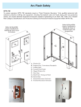
6
Arc Flash Energy Specifications
Table 5 below quantifies the hazard level of arc flash energy that each battery system is capable of
producing. Calculations are based on NFPA 70E D.5.1 using the Maximum Power Method applied for a
maximum of six modules in parallel connection.
Configuration Vsys Impedance mΩ Ibf, calc. Iarc IEm cal/cm23x IEm cal/cm2Distance where
IEm=1.2 (Arc
Boundary), inches. Hazard level
GT12V450 12.8 0.34 37833 18916 0.082 0.246 4 0
GT12V525 12.8 0.3 43390 21695 0.094 0.282 5 0
GT12V600 12.8 0.35 36398 18199 0.079 0.236 4 0
GT24V300 25.6 0.32 80000 40000 0.346 1.039 9 0
GT48V150 48 0.9 53432 26716 0.434 1.301 10 0
GT51V150 51.2 0.85 60117 30059 0.52 1.561 11 0
Formula:
Iarc = 0.5×Ibf
IEm = 0.01×Vsys× Iarc×*Tarc÷D2(Arc Flash Energy)
Tarc = 70ms fuse clearing time
Table 5Hazard level of arc flash energy
Category Energy level Typical PPE examples
0 n/a non-melting, flammable materials (e.g. untreated cotton, wool, rayon, etc.)
15cal/cm2Fire resistant (FR) shirt and fire resistant (FR) pants
28cal/cm2Cotton underwear + FR shirt and FR pants
325cal/cm2Cotton underwear + FR shirt and FR pants + FR coverall
440cal/cm2Cotton underwear + FR shirt and FR pants + double layer switching coat and pants
Table 6Hazard/risk classification per NFPA 70E-2018
10. Make the system communication connections between all system devices using the
provided system wiring harness (881-0040-12). Use the labels on the wiring harness
as a guide and follow the “System Diagram for Communication Connection”. Follow
the vehicle manufacturer’s instructions when wiring to the vehicle’s ignition circuit.
11. End devices in the Xanbus network must both be terminated with a 120Ω resistor or a
Xanbus network terminator (PN: 809-0941). When integrating Xanbus devices into a
larger vehicle CAN network, termination resistors are required at each end of the
larger CAN network.
12. Ensure the installation complies with regional, national, and local electrical codes.
13. Make sure all DC and AC connections are secure. Install and put on all necessary
safeguard and covers. Make sure there are no exposed conductors. Remove LOTO.
14. Perform the end-of-line functional check (document number: 976-0361-01-01).
15. Follow the system user guide (document number: 975-0791-01-01) and perform the
following system configurations.
a. Download and install the ComBox Freedom SW app to the tablet.
b. Connect to the system ComBox using the app. See ComBox Owner’s Guide for
login instructions.The default user name is “admin” and the password is
“password”.
c. In the app, go to “Device Parameters” and configure the Freedom SW
inverter/charger settings as follows.
Parameter Value Parameter Value Parameter Value
Low Batt Cut Out 10.5 V Equalize Support Disabled Max Charge Rate 100%
LBCO Delay 10 sec (min) Bulk Voltage 14.6 V Charge Cycle 3-Stage
High Batt Cut Out 14.8 V Absorb Voltage 14.6 V Default Batt Temp Warm
Battery Type Custom Float Voltage 13.4 V ReCharge Volts 12.4 V
-- -- Batt Capacity (as applicable) 630 Ah
600 Ah
450 Ah
Absorb Time 30 min
-- -- Auto Charge Enable Enabled
Table 3Device parameters
5
DC Cable and Fuse Requirements
WARNING
HAZARD OF ELECTRIC SHOCK, FIRE, OR PERSONAL INJURY
Equipment shall only be installed and serviced by qualified electrical personnel who have training,
knowledge, and experience in installing electrical equipment and applying applicable installation codes.
Failure to follow these instructions can result in death or serious injury.
IMPORTANT
lThe following table contains the minimum system DC cable size requirements for
single-insulated copper conductors rated 75°C in free air based on ambient
temperature of 30 °C according to NEC 2017 Table 310.15(B)(17). This table does
not apply to conductors in raceway or conduit, or in ambient above 30 °C.
Device* Typical Amps (A) Cable Size (AWG)**
Alternator 270 4/0
Freedom SW 320 4/0
BMS 300 4/0
Chassis battery 90 2
*cable is from the Device to the DC busbar
**free air, 30 °C ambient
Table 4Minimum system DC cable size requirements

Freedom e-GEN System Installation Guide for OEM Installers http://www.xantrex.com
4Copyright © 2019-2020 Xantrex LLC. All Rights Reserved.
All trademarks are owned by Xantrex LLC and its affiliates.
975-0790-01-01 Rev J
Dec 2020
CHARGER
AC INPUT
REM
BTS
Wiring box cover must be in place during
use to reduce risk of injury to persons
PASS-THRU
AC INPUT
INVERTER
AC OUTPUT
AC
IN
AC
OUT
AC GROUNDS
(BEHIND COVER)
WARNING: INCORRECT BATTERY
P
O
LA
RIT
Y
W
ILL
CAUSE D
AM
AG
E
T
O U
NIT.
N1
L1
N2
L2
N
L1
L2
Xantrex Battery
built-in
GFCI kit
Neutral
Line
AC IN
AC OUT
busbar
busbar
vehicle
engine vehicle second alternator
neg(–)
pos(+)
See Table 1 for a
list of approved
fuse options.
DC load branch
circuit breaker or
fuse
service disconnect
BMS
neg(–)pos(+)
Secure the DIN connectors
together with a tie wrap.
ON/OFF RESET button
BTS connector
pressure balancing valve
AC IN
AC OUT
20.4-21.7 Nm
1.5-1.7 Nm
15.82 Nm
all studs
15.82 Nm
all studs
9.02 Nm9.02 Nm
21.47 Nm max
fuseholder
Consult alternator manufacturer for torque values 3-inch clearance
3-inch clearance
wire nut
GB-6
(76B) wire nut
GB-6
(76B) to GFCI
line side
15
System Diagram for Power Connection
EQUIPMENT DAMAGE
The system diagram is for information and illustration purposes only. Always use a professional
installer that satisfies the requirements for a qualified personnel.
Failure to follow these instructions can result in damage to equipment.
NOTE:
• The diagram is for information and illustration purposes only. Images are not-to-scale.
• The system diagram is not intended to guide the actual placement of equipment.
• Read and follow “DC Cable and Fuse Requirements” section.
NOTE:
To add a SOLAR kit,
see the Xantrex Solar
Kit Guide, document
part number
975-0808-01-01.
DC – cable
DC + cable
Chassis ground
LEGEND
black = LINE/HOT
AC cable white = NEUTRAL
green/bare = GROUND
Ground
DC negative
disconnect
Heating mat adhered to battery case
DC load
15A DC
fuse (max)
2-pole
DC disconnect
(recommended)
Combiner
Chassis IGN (red)
Solenoid Positive (blue)
Lithium Battery (yellow)
Ground (black)
Chassis Battery
DC Bus
Combiner Wiring Diagram
MEG100
100A FUSE
To IGN
control
Only required
on 51V
systems.
Heat temp
sensor
solar panel
solar charge controller
15A DC fuse

http://www.xantrex.com Freedom e-GEN System Installation Guide for OEM Installers
975-0790-01-01 Rev J
Dec 2020
Copyright © 2019-2020 Xantrex LLC. All Rights Reserved.
All trademarks are owned by Xantrex LLC and its affiliates.
5
busbar
busbar
vehicle
second
alternator
DC load
vehicle
engine
Balmar
regulator
neg(–)
pos(+)
LCD
display
low battery
alarm LED
remote ON/OFF
reset button
System Remote Panel
vehicle
ignition system
engine battery
key ignition
1
65
92
3
4
BMS
neg(–)pos(+)
AC Adapter
AC Sense 12VDC
120VAC
serial port for diagnostics
field
ALT Temp (–)
Amp Seal
connector
ALT Temp (+)
10A 32VDC BLADE
2A 32VDC BLADE
butt splice/spade connector
1A 32VDC
BLADE
Ethernet
Xanbus
Xanbus
router
power
System Diagram for Communication Connection
EQUIPMENT DAMAGE
The system diagram is for information and illustration purposes only. Always use a professional
installer that satisfies the requirements for a qualified personnel.
Failure to follow these instructions can result in damage to equipment.
NOTE:
• The diagram is for information and illustration purposes only. Images are
not-to-scale.
• Route data cables away from devices that can potentially interfere with data
communications.
CAN device in
CAN network
terminator
120Ω
resistor
terminator
120Ω
resistor
IMPORTANT:
• End devices in the Xanbus/CAN
network must be terminated with a
Xanbus network terminator or 120Ω
resistor.
/