VTech 20-2432 Owner's manual

Category
IP phones
Type
Owner's manual

This manual is also suitable for

1
When using your telephone equipment, basic safety precautions should always
be followed to reduce the risk of fire, electric shock and injury, including the
following:
1. Read and understand all instructions.
2. Follow all warnings and instructions marked on the product.
3. Unplug this product from the wall outlet before cleaning. Do not use liquid
cleaners or aerosol cleaners. Use a damp cloth for cleaning.
4. Do not use this product near water (for example, near a bath tub, kitchen
sink, or swimming pool).
5. Do not place this product on an unstable cart, stand, or table. The product
may fall, causing serious damage to the product.
6. Slots and openings in the cabinet and the back or bottom are provided
for ventilation. To protect it from overheating, these openings must not
be blocked by placing the product on the bed, sofa, rug, or other similar
surface. This product should never be placed near or over a radiator or
heat register. This product should not be placed in a built-in installation
where proper ventilation is not provided.
7. This product should be operated only from the type of power source
indicated on the marking label. If you are not sure of the type of power
supply to your home, consult your dealer or local power company.
8. Do not allow anything to rest on the power cord. Do not locate this product
where the cord will be abused by persons walking on it.
9. Never push objects of any kind into this product through cabinet slots as
they may touch dangerous voltage points or short out parts that could
result in a risk of fire or electric shock. Never spill liquid of any kind on
the product.
10. To reduce the risk of electric shock, do not disassemble this product.
Opening or removing cabinet parts other than specified access doors may
expose you to dangerous voltages or other risks. Incorrect reassembling
can cause electric shock when the appliance is subsequently used.
11. Do not overload wall outlets and extension cords as this can result in the
risk of fire or electric shock.
Important Safety Instructions
2
12. Unplug this product from the wall outlet and contact the Supplier under
the following conditions:
A. When the power supply cord or plug is damaged or frayed.
B. If liquid has been spilled into the product.
C. If the product has been exposed to rain or water.
D. If the product does not operate normally by following the operating
instructions. Adjust only those controls that are covered by the
operating instructions, because improper adjustment of other controls
may result in damage and will often require extensive work by an
authorized technician to restore the product to normal operation.
E. If the product has been dropped and the cabinet has been damaged.
F. If the product exhibits a distinct change in performance.
13
. Avoid using a telephone (other than a cordless type) during an electrical
storm. There may be a remote risk of electric shock from lighting.
14. Do not use the telephone to report a gas leak in the vicinity of the leak.
SAVE THESE INSTRUCTIONS
Important Safety Instructions
3
The 20-2432 is an advanced cordless telephone that operates in the 2.4GHz
frequency range. Your 20-2432 is capable of supporting up to a maximum
of 8 Handsets. Using additional Handsets, several people can be using the
cordless system at the same time. For example:
2 Handsets conferenced on a Line 1 call; while 2 additional Handsets are
conferenced on a Line 2 call.
2 Handsets conferenced on a Line 1 call; while another Handset is in
intercom mode with the Base Unit.
1 Handset on Line 1; a different Handset in Intercom mode with the Base
Unit; 2 additional Handsets are conferenced on Line 2.
This manual is designed to familiarize you with the 20-2432 cordless
telephone. We strongly recommend you read the manual before using your
phone.
Introduction
MENU DRIVEN DISPLAYS
The 20-2432 Handset and Base feature a user-friendly display, making it easy
to access the many features of this multi-Handset, cordless system. The three
black keys, found directly below the LCD screen, are called The function of
the softkeys changes depending on what you're doing, here are some
examples:
For example, when the Handset is in the idle mode, the LCD displays:
In this case, the three softkeys access REDIAL, MENU and MEMORY.
When the Handset is active, the LCD displays:
In this case, the three softkeys access VOLUME, HOLD and MUTE.
4
Parts Check List
5. Batteries (2)
6. Belt Clip
7. Owner's Manual
8. 2.5mm Headset
1. Base Unit
2. Handset
3. AC Power Adapter
4. Telephone Cords
Telephone Line Cord
AC Power Adapter
Handset
Base Unit
Belt Clip
2.5mm Headset
Owner's Manual
OWNER'S MANUAL
Batteries (2)
5
The Handset Layout
1. Antenna
2. Message Waiting Indicator
3. Earpiece
4. Headset Jack (2.5mm)
5. Scroll Keys
6. Line 1 (Flash)
7. Dialing Keys (0-9,*,#)
8. Handsfree Speakerphone
9. LCD Display
10. Select/OK
11. Off (Clear)
12. Line 2 (Flash)
13. Battery Compartment
(back of Handset)
14. Billed Services Key
15. Intercom/Transfer Key
16. Microphone
1
3
4
5
6
7
8
9
10
12
16
13
2
14
15
11
6
1. Message Waiting Indicator
(Line1, Line2)
2. Spare Battery Indicator
3. Charge Indicator
4. Charging Contacts
5. Auto Callback Key
6. 3-Way Calling Key
7. Repeat Dialing Key
8. Speakerphone Key
9. Line 1 Key
10. Data Jack
11. Line 1 Jack
12. Line 2 Jack
13. DC Connector
14. Headset Jack
15. LCD Display
16. Scroll Keys
17. Select Key
18. Clear Key
19. Volume Keys
20. Intercom/Transfer Key
21. Mute Key
22. Dialing Keys (0-9,*,#)
23. Hold Key
24. Flash Key
25. Redial Key
26. Line 2 Key
27. Headset Key
28. Spare Battery Drawer
29. Spare Battery Release
The Base Unit Layout
1
16
17
8
9
4
5
18
20
19
21
22
23
24
25
2
3
15
26
27
6
7
LINE 2
LINE 1/
L1 + L2
7V DC
!
COMPLIES WITH 47 CFR PART 68
REGISTRATION NO.: US: EW7 WI00B80-513700
RINGER EQUIVALENCE: 0.0B
USOC JACK: RJ11C, RJ14C
THIS DEVICE COMPLIES WITH PART 15 OF THE FCC RULES. OPERATION
IS SUBJECT TO THE FOLLOWING TWO CONDITIONS: 1)THIS DEVICE MAY
NOT CAUSE HARMFUL INTERFERENCE; AND 2) THIS DEVICE MUST
ACCEPT ANY INTERFERENCE RECEIVED, INCLUDING INTERFERENCE
THAT MAY CAUSE UNDESIRED OPERATION.
PRIVACY OF COMMUNICATIONS MAY NOT BE ENSURED WHEN USING
THIS PHONE.
MODEL : 20-2432
VTECH TELECOMMUNICATIONS LTD.
MANUFACTURED IN CHINA
FCC ID: EW780-5001-00
HAC
12
13
14
11
10
28
29
7
Setup
Plug the AC power adapter into an electrical outlet, and the DC connector
into the back of the Base unit.
Connecting to the telephone lines
Your 2-Line 20-2432 will work fine even if you only have one telephone line.
We recommend connecting the modular telephone cord to the jack labeled
LINE 1 / L1 + L2, located on the bottom of the Base Unit. Here are steps for
connecting 2 lines:
If you have 2 Lines coming out of a Single Wall Jack:
Connect a 4-wire (RJ-14) modular phone cord between the wall jack and the
phone jack labeled L1 / L1 + L2.
If you have 2 Lines, each coming out of Separate Wall Jacks:
Connect a modular phone cord from the wall jack you want to designate as
your LINE 1, to the LINE 1 / L1 + L2 jack on the bottom of the Base Unit. Next,
connect a phone cord from the remaining wall jack to the LINE 2 jack on the
Base Unit.
Data Port
Your 2-Line 20-2432 has a Data Port on the back of the Base Unit. This port
provides an easy way to connect your fax machine, laptop computer, modem
or other telephone device for direct access to LINE 2.
The Data Port only provides access to Line 2, so you must have an active line
connected to the LINE 2 jack on the bottom of the Base Unit. Connect a
modular phone cord from the Data Port (look for the small door marked DATA
on the back of the Base Unit) to your fax, laptop, etc.
NOTE: While the Data Port is in use, accidental use of Line 2 by a parallel
phone, your 20-2432, or a Call Waiting ID alert may interrupt the data
transmission.
Getting Started
To AC outlet
To telephone
jack
To telephone
socket outlet
AC adapter
Examples of 1-Line and 2-Line Cords
RJ-11
One line
cord
RJ-14
2 line
cord
LINE 2
LINE 1/
L1 + L2
7V DC
!
COMPLIES WITH 47 CFR PART 68
REGISTRATION NO.: US: EW7 WI00B80-513700
RINGER EQUIVALENCE: 0.0B
USOC JACK: RJ11C, RJ14C
THIS DEVICE COMPLIES WITH PART 15 OF THE FCC RULES. OPERATION
IS SUBJECT TO THE FOLLOWING TWO CONDITIONS: 1)THIS DEVICE MAY
NOT CAUSE HARMFUL INTERFERENCE; AND 2) THIS DEVICE MUST
ACCEPT ANY INTERFERENCE RECEIVED, INCLUDING INTERFERENCE
THAT MAY CAUSE UNDESIRED OPERATION.
PRIVACY OF COMMUNICATIONS MAY NOT BE ENSURED WHEN USING
THIS PHONE.
MODEL : 20-2432
VTECH TELECOMMUNICATIONS LTD.
MANUFACTURED IN CHINA
FCC ID: EW780-5001-00
HAC
7V DC
!
8
Follow the steps below:
1. Remove the battery cover by
pressing on the indent and
sliding downward.
2. Place the new battery in the
Handset with the metal contacts
aligned with the charge
contacts in the battery
compartment.
3
. Replace the battery cover by
sliding it upward.
4. If the new battery is not already
charged, place the handset in
the Base Unit, or a remote
charging stand, and allow it to
charge for 12 hours. After initial
charge, a maintenance charge
of 8 hours should be sufficient.
Installation of Battery in Handset
The original Handset that is shipped with your 20-2432 system will be
automatically registered to the Base. This Handset is HANDSET 1.
As you register additional Handsets to the system, they will be assigned
extension numbers in the following order: HANDSET 2, HANDSET 3,
HANDSET 4, etc.
Whenever a charged Handset battery is installed, the Handset will
automatically begin SEARCHING FOR BASE (if previously registered), or
it will prompt you to ENTER BASE ID to register the new Handset. See
Registration and Operation for details.
Getting Started
1
3
2
9
The handset seems completely
dead, the LCD is completely
clear and does not activate when
you press the keys.
The low battery message is
displayed:
Charging of Handset Battery
The Handset of your 20-2432 cordless telephone is powered by a
rechargeable battery. It charges automatically whenever the Handset is in the
Base Unit.
You should charge the battery for 12 hours when you first receive your
phone. You'll know the battery needs charging when:
IMPORTANT:
1. Do not dispose of a battery in a fire, the cell may explode.
2. Do not open or mutilate the battery. Toxic substances may be released,
causing harm to eyes or skin.
3. Exercise care in handling batteries in order to prevent an accidental short
of the charge contacts, potentially causing the battery to overheat.
4. Do not dispose of this battery into household garbage. Contact your local
recycling organization for recommended disposal sites.
Charging Of Handset Battery
Getting Started
10
Checking for Dial Tone
After the battery is charged press a LINE key on the Handset. PHONE ON
will appear on the Handset display, and you will hear dial tone. If not, see
In Case of Difficulty.
Tone/Pulse Selection
See SELECT TONE/PULSE AT THE BASE UNIT for details.
CAUTION: Use only the power supply provided with your cordless phone.
IMPORTANT:
FOR MAXIMUM PERFORMANCE OF YOUR
CORDLESS TELEPHONE SYSTEM:
1. Choose a central location for your Base Unit.
2. Install your Base Unit and Extension Handsets
away from electronic equipment, such as personal
computers, television sets and microwave ovens.
3. In locations where there are multiple cordless
telephones, separate base units as much as
possible.
4. Install your telephone equipment away from heat
sources and sunlight.
5. Avoid excessive moisture, dust or extreme cold.
Dial Tone
Getting Started
BEFORE USING YOUR HANDSET(S), CAREFULLY PEEL OFF THE PROTECTIVE
FILM COVERING THE DISPLAY.
11
Spare Battery Charger/Power Backup Function
The 20-2432 uses the spare battery charger in the Base Unit to provide
operational backup in the event of a power failure. With a fully charged battery
in the spare battery charger, you will still be able to place and receive calls
from the Handset for up to one hour. During Power Backup mode, you will
not be able to use the Base Unit.
The spare battery can also be used to replace a drained handset battery,
ensuring uninterrupted use.
NOTE:
When using the 20-2432 during Power Backup mode, audio quality may be
compromised due to reduced power availability.
1. Open the spare battery charger
by pressing the release button,
located on the left-hand side of
the Base Unit. A drawer will
open to reveal the spare battery
compartment.
2. Place a battery in the drawer
with the charge contacts facing
up and to the right.
3. Push the drawer closed.
The spare battery charger takes 24
hours to fully charge a drained
battery.
Getting Started
2
3
CAUTION: TO
REDUCE RISK OF FIRE,
USE ONLY VTECH
80-5017-00-00
CAUTION: TO
REDUCE RISK OF FIRE,
USE ONLY VTECH
80-5017-00-00
BATTERY
INSTALL
THIS
SIDE UP
12
Registration and Operation
Registration And Operation Of The 20-2422 Accessory Handset
Your 20-2432 system can operate up to 8 Handsets.
The accessory Handset consists of the following:
Setup Of The 20-2422 Accessory
Handset
1. Plug the AC power adapter into
an electrical outlet.
2. Remove the Handset battery
cover by pressing on the indent
and sliding downward.
3. Place the new battery in the
Handset, with the metal contacts
aligned with the charge contacts
in the battery compartment.
4. Replace the battery cover by
sliding it upward.
5. Place the Handset in the Charge
Cradle, and allow it to charge for
12 hours. After the initial charge,
a maintenance charge of 8 hours
should be sufficient.
Getting Started
Handset
Battery
Charger Unit
Belt Clip
1
3
5
13
Enter Base ID Code
1. After charging the Handset, remove it
from its Charge Cradle; the screen will
display:
alternating with this screen:
2. If, after charging the Handset, you see:
3. Press NEW. You will now see the
ENTER BASE ID screen as described in
step 1.
4. Find the BASE ID Code by doing the
following: (the Base must be in idle (OFF)
mode)
A. At the Base, press MENU
B. Scroll down to DISPLAY BASE-ID
C. Press OK. The Base screen will display
the 15-digit ID Code. Afterwards, it will
return the idle screen.
5. Enter the 15-digit Base ID Code into the
Handset; then press OK.
Registration and Operation
7. If the Handset displays REJECTED BY BASE or continues to display
SEARCHING FOR BASE for well beyond 60 seconds, try the registration
process again by repeating the above steps.
Congratulations! You can now enjoy the benefits of your 2-Line Multi-
Handset system.
6. Wait approximately 15 to 60 seconds. You
will hear confirmation beeps from the Base
and Handset. The newly registered Handset
will now assign itself the lowest handset
number not previously assigned to a
different system Handset (1 through 8).
Getting Started
14
2
1
1
Basic Operation
Handset and Base Icons
Icon
Description
Line In Use indicator
On steady with no number next to it when a parallel set is
in use.
On steady with one or more numbers next to it, indicating
which extensions are using the line. For example, 02
indicates that the Base (0) and Handset 2 are on a call on
Line 1.
Intercom indicator
On steady with the extension numbers currently on an
intercom call. For example, 02 indicates that the Base and
Handset 2 are on an intercom call.
Battery indicator
Cycles (Low, Medium, and High) when Handset battery is
charging.
Flashes when a low battery condition is detected.
Enhanced Mode indicator
On steady when active Handset or Base is in Enhanced mode.
Mute indicator
On steady when the Handset or Base microphone is muted.
Hold indicator
On steady when the line is on hold.
Handset Registration indicator
FF is displayed when a Handset is either not registered, is
searching for a Base unit.
AC Power Failure indicator
On steady when the AC power fails, the spare battery in
the Base Unit is providing power backup.
M
H
Handset and Base Indicators
E
(Only in Handset)
(Only on Handset)
P
15
Basic Operation
Handset LEDs
Message
Waiting
Base LEDs
LED
Line 1 Message
Waiting/Line 2
Message Waiting
Line 1
Line 2
Handset
Charging
Mute
Speakerphone
Description
Flashes to indicate that you have new messages in your
voicemail. Service must be subscribed to through your local
telephone company.
Description
Flashes to indicate that you have new messages in your
voicemail. Service must be subscribed to through your local
telephone company.
Lights when line is being used by the 20-2432 system.
Flashes when another telephone on the same line (parallel
extension) is in use or when line is on hold.
Lights whenever the Handset is placed in the Base Unit
charging cradle.
Lights when Base microphone is muted.
Lights when Base Speakerphone is in use.
• Lights when a Spare Battery pack is charging in the Base
Unit charger.
Spare Battery
Headset
Lights when the Headset option is in use on the Base
Unit.
Handset and Base Indicators
LED
16
Basic Operation
The 20-2432 has an advanced design
that uses a menu structure and
softkeys to access all of the built-in
features.
Example of the idle mode display:
Soft Menu Functions
RDL (Redial)
Press RDL to display the last 5 telephone numbers dialed. The number on
the top line is the most recent number dialed.
Use the scroll keys to select the desired the number.
To dial the number, you can simply press a LINE or the HANDSFREE
key.
You can erase a redial number by scrolling until it is highlighted, then
press SELECT, then ERASE.
You can save a redial number to phone book memory by scrolling until
it is highlighted, then press SELECT, and then press SAVE. Then add
a name to your entry by following the instructions under To Store a
Number/Name.
HANDSET MENU
With the Handset in the idle (OFF) mode, press the MENU key to access the
following options:
CALL HISTORY (Caller ID)
HANDSET SETTINGS
REGISTER
Use the scroll keys to select the desired option, then press OK.
Press the OFF/CLEAR key to step back through the menu structure. Press and
hold the OFF/CLEAR key to return to the idle menu.
BASE UNIT MENU
With the Base Unit in the idle (OFF) mode, press the MENU key to access the
following options:
CALL HISTORY (Caller ID)
SETUP BASE
DISPLAY BASE-ID
Press the CLEAR key to step back through the menu structure. Press and hold
the CLEAR key to immediately return to the idle menu.
17
Basic Operation
Call History (Caller ID)
NOTES ABOUT CALLER ID & CALL WAITING CALLER ID
These are subscription services, provided by most regional telephone service
providers. You must subscribe to these services to get the benefits of these
features. If you do not subscribe to Caller ID services, you can still use
your 20-2432 and the other features it offers.
Due to regional incompatibilities, Caller ID information may not be
available for every call you receive. In addition, the calling party may
intentionally block their name and phone number from being sent.
Caller ID - Call Waiting ID
Your 20-2432 is capable of displaying the name and/or number of the party
calling before you answer the phone (Caller ID). It is also capable of
displaying Caller ID information in conjunction with a Call Waiting alert
signal (Call Waiting Caller ID). With Call Waiting Caller ID, the Caller ID
data is displayed so you can decide whether to answer the incoming call, or
continue with your current conversation.
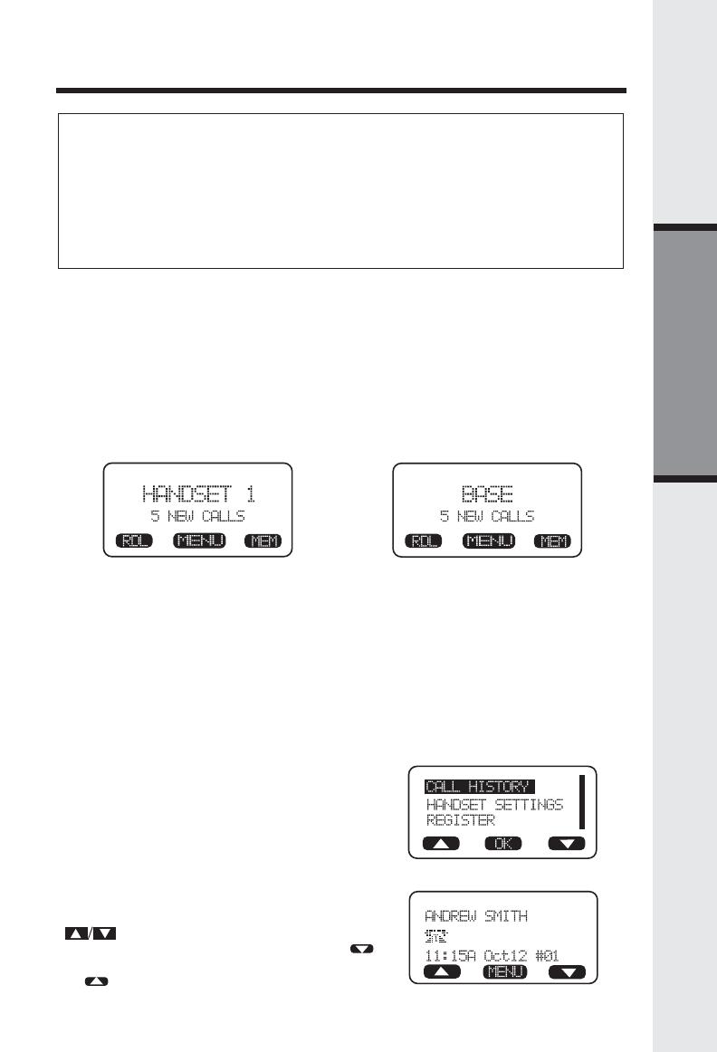
As new Caller ID/Call Waiting ID are received, your Handset and Base
displays will alert to the new, Caller ID records, for example:
The number of new calls displayed on each system Handset and Base
may not be the same. If, for example, you answer a call on Handset 2,
that Handset will not count the Caller ID information for that call as new.
However, the other registered Handsets and Base displays will consider
it a new call, and add it to the NEW CALLS total.
After you review all new Caller ID records, the NEW CALLS status will be
turned off.
The following information explains how to access Caller ID records(Call
History):
From Handset or Base:
• From the idle (OFF) mode, press MENU.
CALL HISTORY is highlighted. Press OK.
The Caller ID information of the most recent
inbound call will be displayed:
• For example: if the call was from Line 1:
• To view other Caller ID records, use the
scroll keys. You can scroll from
newest to oldest record by using the
scroll key, or from oldest to newest by using
the scroll key.
OR
800-595-9511
18
To dial the displayed number, press the
desired LINE key (or HANDSFREE) on the
Handset or SPEAKERPHONE on the Base.
If you need to dial the number differently
than how it is displayed, press MENU. DIAL
OPTION
*
is highlighted. Press OK.
Scroll to the desired dialing option, then
press DIAL or the desired LINE (or
HANDSFREE) on the Handset or
SPEAKERPHONE on the Base to dial.
Basic Operation
Call History (Caller ID)
DIAL OPTION SHORTCUT
With a Caller ID record displayed, press
*
. The 4 possible dialing options
are displayed. Scroll to the desired dialing option, then press DIAL, or
the desired LINE key (or HANDSFREE) on the Handset or SPEAKERPHONE
on the Base to dial.
You can also delete and save Caller ID records in the Directory:
DELETE
With a Caller ID record displayed, press MENU.
Scroll to DELETE CID 4. Press OK.
The CID record is displayed, with the choices THIS (delete only this record)
and ALL (delete all CID records).
If you press THIS, the displayed CID records will be deleted, and you will hear
a confirmation beep.
If you press ALL, the screen will ask you Are You Sure? If you're sure, press
YES, and all CID records will be deleted. If you decide not to delete all CID
records, press NO.
DELETE SHORTCUT
With a Caller ID record displayed, press 4.
The CID record is displayed, with the choices THIS (delete only this record)
and ALL (delete all CID records).
If you press THIS, the displayed CID records will be deleted, and you will hear
a confirmation beep.
If you press ALL, the screen will ask you Are You Sure? If you're sure, press
YES, and all CID records will be deleted. If you decide not to delete all CID
records, press NO.
800-595-9511
595-9511
1-595-9511
800-595-9511
1-800-595-9511
19
Basic Operation
Handset and Base Settings
• RINGERS
NOTE: The Handset and Base ringers are adjusted separately. In addition, each
line is adjusted separately.
Handset:
Press MENU, scroll to HANDSET
SETTINGS, then press OK.
RINGERS will be highlighted; press SET.
Highlight the desired adjustment,
then press SET.
VOLUME: Use to sample
the choices of loudness. There are five:
OFF, LOW, MEDIUM, MEDIUM-
HIGH and HIGH. Press OK to
confirm your selection.
MELODY: Use to sample the six melodies. Press SAVE to confirm
your selection.
Base Unit:
Press MENU, scroll to SETUP BASE, then press OK. Now follow
the same procedure used for the Handset Ringers.
SAVE TO MEMORY
To save a displayed Caller ID record into the directory, press MENU.
Scroll to SAVE TO MEM 7. Press OK. -OR-
With the CID record displayed, press 7. The record has been stored in the
directory.
If the record you wish to save does not have a name (OUT OF AREA, for
example), the screen will ask you to PLEASE ENTER A NEW NAME. Use
the keypad to enter the name, then press SAVE. A guide to the letters and
characters can be found in the section entitled Memory.
20
Basic Operation
CONTRAST
Handset:
Use the
/ scroll keys to make your selection. The Handset display
will automatically adjust as you make your selection. Press OK to confirm
your selection and return to the Handset Settings menu.
Base Unit:
Press MENU, scroll to SETUP BASE, then press SET. Scroll to
CONTRAST; press OK. Press and to adjust the screen contrast,
then press OK to confirm your choice.
Base Unit:
Press MENU, scroll to SETUP BASE, then press SET. Scroll to KEYPAD
TONE; press OK. Choose ON or OFF, then press OK to confirm your
choice.
KEYPAD TONE
Handset:
Select this option to turn the Keypad tones On or Off. Press the OFF or
ON softkeys, to make your selection. Press OK to confirm your selection
and return to the Handset Settings menu. When set to ON, the Handset
will emit a beep whenever a key is pressed. This feature has been preset
to ON at the factory.
SELECT TONE / PULSE AT THE BASE UNIT
With the Base Unit in the idle (OFF) mode, press MENU.
Scroll to SETUP BASE, then press OK.
Scroll to SET PULSE/TONE, then press SET.
Scroll to the desired line; press SET.
Use the UP and DOWN arrow keys to highlight the desired dialing mode
- TONE or PULSE. Press OK to confirm your choice.
NOTE: Your 20-2432 is preset for TONE dialing.
Handset and Base Settings
LOW BATT TONE (Handset only)
Select this option to turn the Low Battery warning tone On or Off. Press
the OFF or ON softkeys, to make your selection. Press OK to confirm your
selection and return to the Handset Settings menu. When set to ON,
the Handset will emit a warning tone when a Low Battery condition is
detected. This feature has been preset to ON at the factory.
RANGE TONE (Handset only)
Select this option to turn the Out of Range warning tone On or Off. Press
the OFF or ON softkeys, to make your selection. Press OK to confirm your
selection and return to the Handset Settings menu. When set to ON,
the Handset will emit a warning tone whenever the Handset is taken out
of range of the Base. This feature has been preset to ON at the factory.
·
·
·
·
·
  • Page 1 1
  • Page 2 2
  • Page 3 3
  • Page 4 4
  • Page 5 5
  • Page 6 6
  • Page 7 7
  • Page 8 8
  • Page 9 9
  • Page 10 10
  • Page 11 11
  • Page 12 12
  • Page 13 13
  • Page 14 14
  • Page 15 15
  • Page 16 16
  • Page 17 17
  • Page 18 18
  • Page 19 19
  • Page 20 20
  • Page 21 21
  • Page 22 22
  • Page 23 23
  • Page 24 24
  • Page 25 25
  • Page 26 26
  • Page 27 27
  • Page 28 28
  • Page 29 29
  • Page 30 30
  • Page 31 31
  • Page 32 32
  • Page 33 33
  • Page 34 34
  • Page 35 35
  • Page 36 36
  • Page 37 37
  • Page 38 38
  • Page 39 39
  • Page 40 40
  • Page 41 41
  • Page 42 42
  • Page 43 43
  • Page 44 44
  • Page 45 45
  • Page 46 46
  • Page 47 47

VTech 20-2432 Owner's manual

Category
IP phones
Type
Owner's manual
This manual is also suitable for

Ask a question and I''ll find the answer in the document

Finding information in a document is now easier with AI