AMrilDilril@
ft{lTl
COMMUNICATIONS
g
o
-
a
g
c
-
o
5
l-
$
l-
o
AT60-3
&
ATI
20-3
Mixer
Amplifiers
^6,
3
A{.
ffi
ColtF
r*l'!ll
iErta
Audio Telex
Communications Pty Ltd
ACN
001345482
lncorporatsd ln t{SW
NSW & ACT
QLD
& NT
149 Beaconsfleld
Street
Prlvate
Bag
149
Sllverwater NSW 2'128
Austrella
Ph02s64T 14't1
Fax 02 9648 3698
42 Commercaal Road
PO Box 871
Fortltude Valley
QLD
4006
Ph 07 3852 1312
Fax 07 32521237
2!277 nudlEDp,rough Road
Box Hlll VIC
3128
PO Box
'15'l
Blackbum South VIC
3130
Ph 03 9890 7477
Fax 03 9890 7977
7/64€6
Kent Street
PO Box
489
Cannlngton
WA 6107
Ph 08 9356 2761
Fax 08 9356 2762
El€ctronlc
Concepts Pty
Ltd
76
George Street
Thebarton SA
5031
PO Box 7034
Hutt Stre€t
Adelald€ SA 5000
Ph 08 8234 9444
Fax
08 8234 9441
K W tcculloch
Pty Ltd
&la Alb€rt Road
lroonah TAS 7009
Ph 03 6228 6373
Fax 03 6278 1063
Unlt
B,
11 Plermark Orlve
PO Box 5{ 2
Albany NZ 1331
Ph 09 415 9426
Fax 09 415 9864

AT60-3
Mixer
Amplifier
ATI 2O-3
Mixer
Amplifier
Product
Description
Th9
AT60 is
a 60
$€tt mixer
amplifier
and
similarly
the
ATl20
is
a
l2o
*ztt mixer
amplifier.
Both models
operate
on 240 VAC,
50
Hz
(or
I l0 VAC
with factory
modificauon)
and may
be desk
or rack mounted
via
an optional rack mount
kit.
Both amplifie6
incorporate
a 6 zone 100
volt
line
sfraker zone
selector with
all
call.
The
A,T60 will
deliver 60
watts into
a
load
of
g
otrms, ZO
or
100
volt line.
The
AT120
will
deliver 120 watts into
a
load
of
.l
or
8
ohms. 70
or
100
volt line. As
standard
both models
are self
standing
and
come with
rubber feet.
They may
be stacked
to a maximum
of four
units high.
Front
Panel Controls
t. Dual
llicrophone/Line
Gain
Controls:
The +
duat mic/line
inpur
controls
are labelled
ch I
through
ro Ch 4
and should
be adjusted
to
provide
the rcquired
mix levet
for
each
individual
channel.
Start with
the controls
set to level 0
and
turn
the controls
clockwise
until the
desircd mix
level for
each
channel is reached"
Bass
Tonal
Control:
Sening this
contml in
the cente
position
will
give
an
overall flat
bass response
!o
the output
of
the amplifier'
Adjusting
the
bass control in
a clockwise
direction
will
provide
up ro 12
dB
of bass boo tt
q
rco ut.
Adjusting
the bass control
in
a counter-clockwise
direction
will
provide
up to
-12
dB
of bass o,tr
@
loo Hz.
Treble
Tonal
Control:
Setting
this control
in the
centre
position
will
give
an overall
flat treble
response
to the
output
of the amplifier.
Adjusting
&e Feble
control in
a clockwise
direction
will
provide
up
to
lo
dB
of rebt;
boosr
g
touiy.
Adjusting
the treble
control in
a counter-clockwise
direction
will
provide
up
to
-lO
dB of
treble cut
@
lO l'l]|z.
aster
Output
Control:
This
controls
the overall
output level
of the arnplifier
depending
on the levels
set for
the
individual
iryut
mir
channels
as detailed
above.
Start with
the control
s€t to
level
0 and
tum
clockwise until
the d€sired
output
level
of the amplifier
is reached
All Call
Button:
When
pressed,
this orange
button wilt
connect
the 100
volt output
of rhe
amplifier
to
all 6 of the
switched outFrts
of
the amplifier.
Depressing
this
button
again will
disconnect
the switcha
ofiputs. fnis
swiah is
,.push
on-
push
of' and is non-interlocking.
Speaker
Selector
Switches:
Thes€ 6
black
buttons are for
swirching
rhe 100
volr output
of the
amplifier
to any
combination
of fte 6
available speaker
zones.
The
switches
are'push
on-push
off'and are non-interlocking (boi6
with
eacir
other
and with
the all-call
button).
The maximum
capacity
of each slBaker
zone is 60
watts
so care
should
be taken
to ensure
that no individual
zone is
loaded
down
with
any morc than 60
watts,
always remembering
that
the total load
for the
AT60 is 60
watts in
total
and for the
ATl20, 120
watts
in total.
Eg; It is
pnssible
on
the ATl20, for
example,
to safely
have
one zone
loaded
with 60
watts
and the remaining
five loaded
with l2
wans
each.
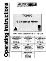
3.
4.
5.
Ar 1
20
EuDionirft

7. Limit
LED: This red LED is designed
to
give
the us€r an
indication
of the operating
condilion of the amptifier and is
integral
to the
inbuilt
protection
included in the
amplifier.
This LED will
glow
red if the amplifier is operating
into
an excessive
load
or
ifone
or mor€ of the input
channels
is
supplving an unacceptably high
level
ofsignal. It is
normal
for this
LED
to flicker
on and
off
howwer. if
it
glows
steaqt^ . the amplifier will
shul
down for a
period
of approximately 3 seconds and continue to
cycle
in
this fashion
until the abnormal connection is removed
or
rectified. This is
a
featue
of the amplifier designed to
protect
the
amplifier circuitry
ald the speaken
connected to the output.
Powef
Button:
ThiE
switch controls the swilching of AC
power
to the amplifier. Rocking this switch upwards
turns on
AC
power
to the amplifier
while rockhg
the switch downwards turns
power
off to the amplifier. When in the upard
positio4
the red neon in
the body of
the switch will
glow.
Rear Panel Connections
t. 3 Pin IEC ilains
Power Inlet:
the
operating voltage is 240 VAC
@
50Hz
or
lloVAC@60H2.
The AC
power
voltage level is not
extemally user adjustable
but is factory
pre-set.
The intet is
equippea with
an
inhilt AC
fus€ holder fitted
with a 4
amp ftse
(ATl20)
or a 2
amp fuse
(AT60)
plus
a spare
for
each found within the holder.
Fower conslmption is 225VA
for the ATl20
and l25VA for the 4T60.
* Please ensure
that the mains
prower
cord is dhconnected
before attempting to ch€ck
or
r€place
this fuse.
z. Direct Output
Terminal
Strip: fnese
screw terminals allow
access to the direct outpurs of rhe amplifier. 2
spare
screw terminals
allow for the connection
ofvarious tone module accessories. Reading from
left to right the terminals
are-
o
Low Impedance
Common
o
4
Ohms
(Not
aYailable
on
AT60)
.8Ohms
.
Constant Voltage
Common
.
T0
Volt Line
.
l@ Volt Line
o
Spare
o
Spare
Note:
The minimum impedance
at any time
on maximum load for 100 Volt line
shoutd be no less
than
E0
Ohrns
for
the AT120
and
no less
than 170 Ohns for
the
4T60.
3. Switched Outputs
Terminal
Strip: neaalng from left
to right these
screw terminal
pairs
correspond
to the
switched 100 volt line
outputs numbercd
6 through I as indicated
on the
front
panel
of the
rmplifier.
For each
pat,
the left
hand
terminal is the common
and the right hand
terminal is the 100 volt
output
Tape Output:
RCA
style
phono
output connector for line level
output. Provides
a
maximum
of
350mV into
10K
Ohms,
ideal for
a connection to most
standard
tape
recorders.
This outFut is sourced
before the master
gain
control and
as such,
the
tape output level is not inlluenced
by
the operation of the master
gain
control.
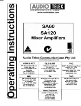
4.
'r
I,1r'1'r
po1'ori
i-i
-r_-T
r
-
@@@@o

s. Active Balanced, XLR Sockets ForThe
llicrophone lnputs. with an
input
sensitiviry
of
0.8mv
@
200
ohms.
Pin
connections are:
pin
#l-earth;
pin
#2-active
(high, +)t
pin
#3-active
(low,
-).
Phantom
fnwer
of
+15
volts is
available on all microphone inputs. Reading from left to right across the rear
panel,
the connection
are for microphone inputs 4,
3,2,&lrespectively.
6. RCA Sockets For The Monaural Line Level lnputs.
Inputs #'s 1,2
&
3 llave
an
input
sensitivity of
75mV
@
47K
ohns. Input
l'4
has an inp.rt
sensitivity of
250 mY
@
4TK ohms making
it
suitable
for high level inpuls such as a
CD
player.
Reading from left to right
across the
rear
panel,
the connections
are for inputs 4, 3, 2, & 1 respectively.
Optional Accessories
I
The installation
of some of the following optional acc$sories
involves
access to the
inside
of the amplilier.
Installation
should only be attempted by a
qualified
technician.
Always
turn olf the
AC
power
and
remove the
AC power
cord before
attempting to
rccess th€
inside
of the amplifier.
Please
contact
your
near$t Audio Telex
ofiice
for details of
your
nearest
qualified
technician.
Tone
Genefators: Four
separale tones are available as an option \/ia the
ATC5488
tone
gpnerator
board.
This intemally
mounred PCB
is €asily fitted and
plugs
dircctly into
a socket
provided
on the
intemal
circuit board
PCB6I9E. Please follow
the
inslructions
supplied
with the
tone
generator.
When any tone
from
the
ATC5488 is acti ted all inputs will automatically mute
except
for input
one.
Tones available on the ATC5488 tone
generator
board are:
Evacuation
Tone
(to
Australian Standard L5222O.1.2)
Alert Tone
(to
Australian Standard A52220.1.2)
Bell Tone
Pre Announce
Chime
TX3010 Vox tuting Module.
When
installed
(as per
the comprehensive
instructions
supplied with the
fi3010),
channel I of the ampl.ifier
will
mute
channels
2, 3
&
4
of the amplifier.
ATR KBLK. 19" rack mount kit
Fuse Sizes ATI 20 Amplifier
tains 240
VAC: 4 Ampercs
Slow Blow
Fuse Sizes AT60 Amplifier
tains 240 VAC: z Ampres
Slow
Blow
Notes
The DC fts€
is located
on the circuit board. This is a feature of the AT series amplifien, which
is
equip,ped
with a cwrenr limiting
circuit
preventing
excessive
DC
currents, thus eliminating the
risk
of blowing
high
lension fuses.
In the unlikely event that the DC
fuse actuates, the output transistors should be checkd as it is
probable
thar the amplifier
has
been subjected to very extreme
conditions-
/