ADDER AdderLink Infinity Manager User manual

Category
Networking
Type
User manual
AdderLink Infinity
User Guide

Infinity System Software Version 1.0 (with addendum for version 1.3 - see page 2)
www.adder.com
AdderLink
NET SER AUD USB DVI PWR
T R A N S M I T
 




1
Contents
Introduction
AdderLink Infinity TX and RX unit features ...............................4
What’s in the box.........................................................................5
What you may additionally need ...............................................6
Installation
Mounting .....................................................................................7
Using the VESA mounting bracket ........................................8
Connections .................................................................................9
TX video link and audio links ...............................................10
TX USB and AUX ports ..........................................................11
TX power in ...........................................................................12
TX/RX network link ...............................................................13
RX video display, microphone & speakers ...........................14
RX USB and AUX ports .........................................................15
RX power in ...........................................................................16
Configuration
Initial configuration ..................................................................17
Manual factory reset ............................................................17
Infinity Start-of-Day configuration utility ...........................18
Infinity browser-based configuration utility .......................19
TX (transmitter) unit configuration ................................20
RX (receiver) unit configuration ......................................21
Performing an upgrade.............................................................23
Operation
Front panel indicators and True Share .....................................24
Many-to-one control .................................................................25
Further information
Getting assistance ......................................................................26
Specifications .............................................................................27
Appendix 1 - TX configuration utility ......................................28
TX System Configuration page ............................................28
TX Video Configuration page ..............................................29
TX Firmware Upgrade page .................................................30
TX System Messages page ....................................................31
TX Reboot page ....................................................................32
TX Support page ...................................................................33
Appendix 2 - RX configuration utility ......................................34
RX System Configuration page ............................................34
RX System Configuration page (lower half)........................35
RX Firmware Upgrade page .................................................36
RX System Messages page ....................................................37
RX Reboot page ....................................................................38
RX Support page ...................................................................39
Appendix 3 – Configuration examples .....................................40
One-to-one configuration ....................................................40
One-to-many (True Share) configuration ............................41
Appendix 4 – Addresses and net masks ...................................42
Appendix 5 – Cable and connector specifications ...................44
Appendix 6 – Supported video modes .....................................45
Warranty ....................................................................................46
Safety information ....................................................................46
Radio Frequency Energy............................................................47
Index
See Important Information on page 2.
 




2
Important information
Please read before using the rest of this guide.
Various places in this guide refer to the default IP addresses of the units.
These are correct for Infinity units that use firmware v1.0:
Tx: 192.168.16.129
Rx: 192.168.16.127
For firmware versions v1.3 or higher, Infinity units now use “zero configuration”,
a feature which makes installations within larger systems substantially more
straightforward. This has necessitated a change of default IP addresses to the
following:
Tx: 169.254.1.33
Rx: 169.254.1.32
Where a default netmask setting is required, use the following for both
Tx and Rx units:
v1.0: 255.255.255.0
v1.3 and above: 255.255.0.0
 




3
INFINITY RX
INFINITY RX
INFINITY RX
INFINITY TX
Gigabit
Ethernet
One-to-many configuration (also known as True Share)
Using multicast techniques, an unlimited number of receivers* can
receive video and audio data streams from a single TX unit.
Introduction
Thank you for choosing AdderLink Infinity. AdderLink
Infinity represents a major advance in the capabilities of
digital extenders and switches. By encoding high quality
DVI video, digital audio and USB connections into Internet
Protocol (IP) messages, AdderLink Infinity offers highly
advanced and flexible signal switching capabilities.
Adder’s extensive knowledge of interfacing techniques
and high speed networking has allowed us to develop
new ways to break the chains of local DVI, USB and audio
connections. With AdderLink Infinity, distance is finally no
barrier to high specification, high performance computing.
Furthermore, since all signals are now IP, the most elaborate
and yet simple-to-use switching and multicast techniques
make possible a great variety of uses.
The AdderLink Infinity units come in two forms: a TX
transmitter and an RX receiver. The former attaches to
a single computer; the latter to your DVI video monitor,
microphone, speakers and up to four USB peripherals. The
distance between them is limited only by the size of your
Gigabit Ethernet network.
In addition to separating one computer and its peripherals,
AdderLink Infinity promotes sharing. You can arrange for
a limitless number of screens and speakers, distributed
anywhere across the network, to receive video and audio.
You can also switch between any number of transmitter
units from a single screen, keyboard and mouse in order to
monitor a potentially vast collection of remote systems.
All units feature browser-based configuration utilities to
allow quick and easy set up, from near or far.
One-to-one configuration
The simplest configuration links one RX unit to a single TX unit, either by a direct
link (up to 100m) or over much greater distances via a Gigabit Ethernet network.
INFINITY RXINFINITY TX
Many-to-one (and many-to-many) configuration
Each RX unit can switch between different TX units. Multiple instances of many-to-one
and one-to-many configurations produce a highly flexible many-to-many installation.
INFINITY RX
INFINITY RX
INFINITY RX
INFINITY TX
INFINITY TX
INFINITY TX
Gigabit
Ethernet
* A maximum of twelve concurrent USB inputs (via
multiple RX units) are permitted to a single TX unit.
 




4
www.adder.com
AdderLink
NET SER AUD USB DVI PWR
T R A N S M I T
AdderLink Infinity TX and RX unit features
The AdderLink Infinity units are housed within durable, metallic enclosures with most connectors situated at the rear
panel - only the Ethernet ports are situated at the front panel. The smart front faces feature the operation indicators.
Infinity TX (transmitter) - front Infinity RX (receiver) - front
Infinity RX (receiver) - rear
www.adder.com
AdderLink
R E C E I V E R
NET SER AUD USB DVI PWR
Infinity TX (transmitter) - rear
AUX
LINE IN
LINE OUT
COMPUTER
ON
21
INDOOR
USE ONLY
OPTIONS
1 2
5V
2.5A
DVI-D
Video
input
Audio
line
in/out
AUX
(serial)
port
USB
port
Configuration
switches
Power
input
INDOOR
USE ONLY
OPTIONS
AUX
LINE IN/
LINE OUT
DVI-D
1 2
USER CONSOLE
5V
2.5A
ON
21
MIC IN
Video
output
Audio
line
in/out
AUX
(serial)
port
USB
ports
Configuration
switches
Power
input
Gigabit
Ethernet
port
Gigabit
Ethernet
port
Indicators
These six indicators clearly show the key aspects of operation:
NET On when valid network link is present.
Flashes when the unit is in error.
SER On when the AUX (serial) port is enabled and active.
AUD On when audio is enabled and active.
USB On when USB is enabled and active.
DVI On when DVI video is enabled and active.
PWR Power indicator.
 




5
Combined DVI-D and USB
cable (1.8m)
AdderLink Infinity TX unit
CD-ROM
Four self-adhesive
rubber feet
Power adapter
(12.5W) and
country-specific
power lead
Whats in the box
2 x Audio cable 2m
(3.5mm stereo jacks)
Serial null modem cable 2m
(Upgrade cable)
AdderLink Infinity TX package
Infinity
quick guide
AdderLink Infinity RX unit
CD-ROM
Four self-adhesive
rubber feet
Power adapter
(12.5W) and
country-specific
power lead
Infinity
quick guide
AdderLink Infinity RX package
A
d
d
e
r
L
i
n
k
T
R A N S M IT
NET
SER
AU
D U
SB
DV
I
PW
R
w
w
w
.
a
d
d
e
r
.
c
o
m
A
d
d
e
r
L
i
n
k
R E C E I VE R
NET
SER
AU
D U
SB
DV
I
PW
R
w
w
w
.
a
d
d
e
r
.
c
o
m
 




6
What you may additionally need
Combined DVI-D and USB (USB type A to B) cable
Part numbers: VSCD3 (1.8m length)
VSCD4 (5m length)
Two 19” rack-mount brackets and four screws
Part numbers:
One unit per 1U rack slot: RMK4S
Two units per 1U rack slot: RMK4D
Single link DVI-D to DVI-D video cable
Part number: VSCD1
Power adapter (12.5W) and
country-specific power lead
Part number: PSU-IEC-5VDC-2.5A
Audio cable 2m
(3.5mm stereo jacks)
Part number: VSC22
Serial null modem cable 2m
(Upgrade cable)
Part number: CAB-9F/9F-NULL-MODEM
USB cable 2m (type A to B)
Part number: VSC24
VESA mounting bracket and four screws
(can also be used to secure to walls and
other surfaces)
Part number: RMK4V
 




7
AU
X
LINE IN/
LINE
O
UT
SER
CONSOLE
M
IC IN
1
2
INDOOR
USE ON
L
Y
O
P
T
IO
N
S
LINE IN/
LINE
O
D
VI-D
1
2
USER
CO
5
V
2.5A
M
IC IN
Installation
Mounting
There are three main mounting methods for transmitter and receiver units:
The supplied four self-adhesive rubber feet
Optional rack brackets
Optional VESA mounting bracket
Connections
Rack brackets
The optional brackets (plus four screws), allow the
units to be secured within a standard rack slot.
Note: The Infinity units and their power
supplies generate heat when in operation
and will become warm to the touch.
Do not enclose them or place them in
locations where air cannot circulate to
cool the equipment. Do not operate
the equipment in ambient temperatures
exceeding 40
o
C. Do not place the
products in contact with equipment
whose surface temperature exceeds 40
o
C.
HT
 




8
Using the VESA mounting bracket
The optional mounting bracket conforms to the VESA mounting standard and
so can be used to mount an Infinity unit directly to the rear of most video display
units. The bracket can also be fixed directly to a wall or other solid surface using
appropriate screws or bolts.
To fit the mounting bracket and Infinity unit
1 Orientate the bracket against the rear of the video display so that its small
folded-in tabs are lowermost.
2 Attach the bracket to the video display using four screws of a size
appropriate to the threaded holes within the video display panel - do
not overtighten.
3 Place the Infinity unit into the bracket with its
base facing towards the video
display and the front panel of the
Infinity unit facing upwards.
4 Secure the Infinity unit to the
bracket using the four supplied
screws - do not overtighten.
www
.adder
.com
AdderLink
NE
T S
ER
AU
D
USB
DV
I
PW
R
R E C E I V E R
Rear panel of video display
Infinity unit
VESA
mounting
bracket
 




9
Connections
Installation involves linking the Infinity TX unit to various ports on the host
computer, while the Infinity RX unit is attached to your peripherals:
Click a connection to see details
 




10
TX video link
The AdderLink Infinity units support
DVI digital video signals and so use
DVI-D video connectors.
To make a video link
1 Wherever possible, ensure that
power is disconnected from the
AdderLink Infinity and the host
computer.
2 Connect a digital video link cable to the DVI-D socket on the TX unit rear
panel:
TX audio links
The AdderLink Infinity units support
two way stereo digital sound so that
you can use a remote microphone as
well as speakers.
To make audio links
1 Connect an audio link cable
between the LINE OUT socket on
the TX unit rear panel and the
speaker output (line out) socket
of the host computer.
LINE IN
LINE
O
UT
COMPUTER
COMP
D
VI-D
3 Connect the plug at the other end of the cable to the corresponding video
output socket of the host computer.
2 [Where a microphone is to be used]: Connect a second audio link cable
between the LINE IN socket on the TX unit rear panel and the LINE IN socket
of the host computer.
INFINITY RX
INFINITY TX
VIDEO
LINK
LINK
USB
LINK
AUDIO
LINKS
POWER
IN
SERIAL
LINK
INFINITY RX
INFINITY TX
VIDEO
LINK
LINK
USB
LINK
AUDIO
LINKS
POWER
IN
SERIAL
LINK
DVI-D link from
host computer
Speaker (line out) link
from host computer
Microphone (line in) link
from host computer
 




11
TX USB link
The Infinity units acts as USB 2.0
hubs and so can provide four
sockets at the RX unit with only a
single connection at the TX unit.
To make a USB link
1 Connect the squarer of the two
connectors on a USB cable to
the USB port on the TX unit rear
panel.
O
P
T
IO
N
S
1
2
1
2
2 Connect the other, more rectangular connector of the cable to a vacant USB
socket on the host computer.
TX AUX port
The AUX port connection is not
required for normal operation.
This is an RS232 serial port which
is used when performing an initial
setup or firmware upgrade using
the Start-of-Day configuration utility.
Your computer needs to have a
suitable terminal emulator program,
such as Windows HyperTerminal.
See Infinity Start-of-Day configuration utility for details.
To connect the AUX port (not required for normal operation)
1 Ensure that power is removed from the Infinity unit.
2 Connect a suitable serial ‘null-modem’ cable (see Appendix 4 for pin-out)
between a vacant serial port on your computer and the AUX port on the
right hand side of the Infinity rear panel.
AU
X
INFINITY RX
INFINITY TX
VIDEO
LINK
LINK
USB
LINK
AUDIO
LINKS
POWER
IN
SERIAL
LINK
INFINITY RX
INFINITY TX
VIDEO
LINK
LINK
USB
LINK
AUDIO
LINKS
POWER
IN
SERIAL
LINK
USB link from
host computer
Serial (null-modem) link
from your computer
3 On the rear panel, click option switch 1 to the ON
(down) position.
4 Power up the Infinity unit and your computer. You
are now ready to use the Start-of-Day configuration
utility (Infinity Start-of-Day configuration utility) or
perform an upgrade (Performing an upgrade).
INDOO
R
USE ON
L
Y
O
P
T
IO
N
S
1
2
5
V
2.5A
1
2
 




12
TX power in
Each Infinity unit is supplied with
a standard power supply. When all
other connections have been made,
connect and switch on the power
supply unit
To apply power in
1 Attach the output lead from the
power adapter to the 5V socket
on the rear panel of the unit.
INDOOR
USE ONL
Y
O
P
T
1
5
V
2.5A
1
2 Connect the IEC connector of the supplied country-specific power lead to
the socket of the power adapter.
3 Connect the power lead to a nearby main supply socket.
Note: Both the unit and its power supply generate heat when in operation and
will become warm to the touch. Do not enclose them or place them in locations
where air cannot circulate to cool the equipment. Do not operate the equipment
in ambient temperatures exceeding 40
o
C. Do not place the products in contact
with equipment whose surface temperature exceeds 40
o
C.
INFINITY RX
INFINITY TX
VIDEO
LINK
LINK
USB
LINK
AUDIO
LINKS
POWER
IN
SERIAL
LINK
Power lead from
power adapter
Note: Ensure that
Option switches
1 and 2 are both
in the ‘off’ (up)
position to enable
normal operation
of the unit.
 




13
TX/RX network link
The Infinity units can be either connected directly
to each other or via a Gigabit Ethernet network.
For direct links, the length of cable should not
exceed 100 metres (328 feet). Network cables
used for connections may be category 5, 5e, 6 or
7 twisted-pair cable. The Infinity TX unit has an
autosensing capability on its network interface,
so for direct point-to-point connections, no
‘crossover’ Ethernet cable is required.
To link Infinity units
1 Connect a CAT 5, 5e, 6, or 7 cable to the socket on the front panel of the
Infinity unit.
LINK
INFINITY RX
VIDEO
DISPLAY
USB
DEVICES
MIC &
SPEAKERS
POWER
IN
SERIAL
LINK
LINK
INFINITY TX
VIDEO
LINK
USB
LINK
AUDIO
LINKS
POWER
IN
SERIAL
LINK
www
.adde
r
.com
CAT 5, 5e, 6, or 7 link either
directly from the other Infinity
unit or from a Gigabit Ethernet
switch
2 Connect the other end of the cable either to the other Infinity unit or to a
Gigabit Ethernet switch, as appropriate.
3 [For connections via a network] repeat steps 1 and 2 for the other Infinity
unit.
 




14
RX video display
The Infinity unit supports a single
DVI-D (no analogue signals)
video display via the socket on
the rear panel. See Appendix 5
– Supported video modes for
details.
To connect a digital DVI video display
1 Connect the lead from the video display to the DVI-D socket on the rear
panel of the Infinity unit.
RX microphone & speakers
The Infinity unit can support a
microphone as well as speakers
providing the necessary
connections have been made
between the Infinity TX unit and
the host computer.
To connect a microphone (or line in) and/or speakers
1 Connect the lead from a mono microphone or, alternatively, a line in
connection from an audio device to the 3.5mm socket labelled LINE IN/MIC IN
on the rear panel.
2 Connect the lead from stereo speakers or, alternatively, a line out connection
from an audio device to the 3.5mm socket labelled LINE OUT on the rear
panel.
INFINITY TX
LINK
INFINITY RX
VIDEO
DISPLAY
USB
DEVICES
MIC &
SPEAKERS
POWER
IN
SERIAL
LINK
INFINITY TX
LINK
INFINITY RX
LINK
VIDEO
DISPLAY
USB
DEVICES
MIC &
SPEAKERS
POWER
IN
SERIAL
LINK
LINE IN
/
LINE
O
UT
CONSOLE
M
IC IN
Connection from
microphone or line in
from audio device
Connection from
speakers or line out to
audio device
D
VI-D
DVI-D connection from
video display
3 Once the unit has been fully connected and powered on, access the RX
System Configuration page to check that the Audio Input Type setting
matches the connection that you have made to the port: line, mic or mic
boost (the latter provides +20dB gain).
 




15
RX USB devices
The Infinity RX unit has four
USB ports to which peripherals
may be connected. The ports
are interchangeable. To connect
more than four peripherals, one
or more USB hubs may be used.
The total current that may be
drawn from the USB ports is
1.2A, which should be sufficient
for a keyboard, mouse (no more than 100mA each) and any two other devices
(500mA maximum each). If more power for USB devices is required, use a
powered USB hub.
To connect a USB device
1 Connect the lead from the device to
any of the four USB sockets on the rear
panel of the Infinity unit.
RX AUX port
The AUX port connection is not
required for normal operation.
This is an RS232 serial port which
is used when performing an initial
setup or firmware upgrade using
the Start-of-Day configuration
utility. Your computer needs to
have a suitable terminal emulator
program, such as Windows
HyperTerminal. See Infinity Start-of-Day configuration utility for details.
To connect the AUX port (not required for normal operation)
1 Ensure that power is removed from the Infinity unit.
2 Connect a suitable serial ‘null-modem’ cable (see Appendix 4 for pin-out)
between a vacant serial port on your computer and the AUX port on the
right hand side of the Infinity rear panel.
AU
X
/
LINE
O
UT
INFINITY TX
LINK
INFINITY RX
LINK
VIDEO
DISPLAY
USB
DEVICES
MIC &
SPEAKERS
POWER
IN
SERIAL
LINK
INFINITY TX
LINK
INFINITY RX
VIDEO
DISPLAY
USB
DEVICES
MIC &
SPEAKERS
POWER
IN
SERIAL
LINK
3 On the rear panel, click option switch 1 to the ON
(down) position.
4 Power up the Infinity unit and your computer. You
are now ready to use the Start-of-Day configuration
utility (Infinity Start-of-Day configuration utility) or
perform an upgrade (Performing an upgrade).
Serial (null-modem) link
from your computer
LIN
E
I
USER
CONSOLE
M
IC
I
Connection from USB device
Supported USB Devices
USB devices are supported using True Emulation technology. This means that
the signals of each USB peripheral are emulated to the computer so that full
functionality is available, subject to the following limitations:
Keyboards, mice and other HID devices are supported.
Storage devices (i.e. flash drives, USB hard disks, CD-ROM drives) are
supported, but they may operate more slowly than with a direct connection.
Isochronous devices (including microphones, speakers, webcams and TV
receivers) are not currently supported.
Many other devices (such as printers, scanners, serial adapters and specialist
USB devices) will work, but due to the huge variety of devices available,
successful operation cannot be guaranteed.
INDOO
R
USE ON
L
Y
O
P
T
IO
N
S
1
2
5
V
2.5A
1
2
 




16
RX power in
Each Infinity unit is supplied with
a standard power supply. When
all other connections have been
made, connect and switch on the
power supply unit
To apply power in
1 Attach the output lead from
the power adapter to the 5V
socket on the rear panel of the
unit.
INDOOR
USE ONL
Y
O
P
T
1
5
V
2.5A
1
2 Connect the IEC connector of the supplied country-specific power lead to
the socket of the power adapter.
3 Connect the power lead to a nearby main supply socket.
Note: Both the unit and its power supply generate heat when in operation and
will become warm to the touch. Do not enclose them or place them in locations
where air cannot circulate to cool the equipment. Do not operate the equipment
in ambient temperatures exceeding 40
o
C. Do not place the products in contact
with equipment whose surface temperature exceeds 40
o
C.
INFINITY TX
LINK
INFINITY RX
VIDEO
DISPLAY
USB
DEVICES
MIC &
SPEAKERS
POWER
IN
SERIAL
LINK
Power lead from
power adapter
Note: Ensure that
Option switches
1 and 2 are both
in the ‘off’ (up)
position to enable
normal operation
of the unit.
 




17
Configuration
Initial configuration
The AdderLink Infinity units are designed to be as flexible as possible, and this
principle extends also to their configuration.
Where an Infinity TX and an Infinity RX are directly linked to each other, no
configuration action is required, provided that they have their factory default
settings in place. If the standard settings have been changed in a previous
installation, you merely need to perform a factory reset on each unit:
Where Infinity units are connected via network links, you will need to specify
their network address details. This can be done using a computer system
temporarily linked to each Infinity unit, in either of two ways:
Using a direct serial port connection and the Infinity Start-of-Day
configuration utility.
Using a network connection and the Infinity browser-based
configuration utility. This configuration utility also allows numerous
other settings to be altered.
Note: For basic one-to-one installations, the factory default addresses may
be acceptable for immediate use within your network without the need to
use a configuration utility or change their values:
TX unit (192.168.16.129), RX unit (192.168.16.127).
Manual factory reset
A factory reset returns an Infinity TX or RX unit to its default configuration.
You can perform factory resets using either of the two configuration utilities
or by using this direct manual method.
To perform a manual factory reset
1 Remove power from the Infinity unit.
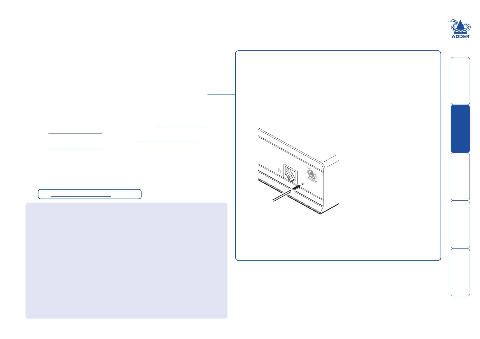
2 Use a narrow implement (e.g. a straightened-out paper clip) press and
hold the reset button adjacent to the front panel network socket. Power
on the unit and then release the reset switch.
After roughly eight seconds, when the factory reset has completed, five
of the front panel indicators will flash for a period of three seconds to
indicate a successful reset operation.
3 Remove and then re-apply power to start the unit in its default
configuration.
www
.adder
.co
m
Use a straightened-out paper
clip to press the reset button
while powering on the unit
Configuring network switches to ensure efficient operation
With IP Multicast there is a risk that network segments can get saturated
with data that is not destined for any device on that segment. Unless some
intelligence is applied, it’s possible for a naive IP switch to pass multicast data
onto every port on the switch. This can lead to performance degredation and
wasted network bandwidth. Fortunately, however, modern switches employ a
technique known as IGMP Snooping (Internet Group Management Protocol)
which enables them to be selective about where they route multicast IP traffic
- routing it only through switch ports which contain devices that are specifically
interested in such traffic.
IGMP Snooping can significantly reduce the amount of traffic generated by
Infinity TX units that are configured for multicast operation. It is beyond the
scope of this document to detail how to enable and configure IGMP snooping
for particular Gigabit IP Switches. However, we strongly recommend that when
deploying an Infinity Network you should select IP switches that support IGMP
snooping, and this snooping should be enabled and appropriately configured.
See Important Information on page 2.
HT
 




18
Infinity Start-of-Day configuration utility
The Start-of-Day configuration utility is useful when you are not able to make
a network connection between your computer and an Infinity unit in order
to use the more comprehensive browser-based configuration utility. The
rudimentary Start-of-Day configuration utility requires a direct serial port link
between your computer and the Infinity unit and allows you to perform only the
following functions:
View/edit the IP network address, netmask and gateway for the Infinity unit,
Perform a firmware upgrade,
Perform a factory reset.
To connect a computer system via the AUX port
1 Ensure that power is removed from the Infinity unit.
2 Connect a suitable serial ‘null-modem’ cable (see Appendix 4 for pin-out)
between a vacant serial port on your computer and the AUX port on the
right hand side of the Infinity rear panel.
3 On the rear panel, click option
switch 1 to the ON (down)
position.
To use the Start-of-Day configuration utility
1 On the connected computer, run a suitable terminal emulator application,
such as Windows HyperTerminal.
2 Within the terminal emulator, ensure that the serial port settings are configured
as follows: 115200 baud, no parity bits, 8 data bits, 1 stop bit. Within
the terminal emulator console, you should see a screen similar to the following:
System Conguration (type “help” for help)
System Information:
Unit type: TX
IP address: 192.168.16.101
Netmask: 255.255.255.0
Gateway: 192.168.16.1
MAC address: 00:0F:58:01:3A:9F
Build no: 1.0.9890:9893M
Built by: snm
Built on: "Tue Sep 09 14:17:35 BST 2009"
Type ‘help’ for help
% >
% >ip
IP Address set to 192.168.16.101
% > ip 192.168.16.109
% >netmask
Netmask set to 255.255.255.0
% > netmask 255.255.0.0
Here the IP address
is first requested
and then changed.
Here the netmask is
first requested and
then changed.
To see a summary of valid commands, type help and press Enter.
To view the current IP address for the unit, type ip and press Enter.
To change the IP address, type ip nnn.nnn.nnn.nnn and press Enter,
(where nnn represents each octet of the appropriate address).
To view the current netmask for the unit, type netmask and press Enter.
To change the mask, type netmask nnn.nnn.nnn.nnn and press Enter,
(where nnn represents each octet of the appropriate mask).
3 When you have completed your settings (changes are saved as they are
made), remove power from the Infinity unit; on the rear panel click option
switch 1 to the OFF (up) position and disconnect the serial lead.
4 Power up the Infinity unit and your computer. You are now ready to use the
Start-of-Day configuration utility.
AU
X
/
LINE
O
UT
INDOO
R
USE ON
L
Y
O
P
T
IO
N
S
1
2
5
V
2.5A
1
2
Link from a vacant
serial port on your
computer
% >gateway
Gateway set to 192.168.16.1
% > gateway 192.168.16.2
Here the gateway address
is first requested and then
changed.
To view the current gateway address, type gateway and press Enter.
To change the gateway, type gateway nnn.nnn.nnn.nnn and press
Enter, (where nnn represents each octet of the appropriate address).
See Important Information on page 2.
 




19
Infinity browser-based configuration utility
The browser-based configuration utility within all TX and RX units requires
a network connection between the Infinity unit and a computer. This
configuration utility allows you to perform all of the following functions:
View/edit the IP network address and netmask,
Configure separate IP network addresses for video, audio and USB,
Configure multicast settings (on RX units),
Configure video bandwidth settings (on TX units),
View the current video output (on TX units),
Perform a firmware upgrade,
Perform a factory reset.
To connect a computer system for browser-based configuration
1 Connect a suitable network cable to the Ethernet port on the front panel of
the Infinity unit.
2 Connect the other end of the link cable to a network switch.
3 Similarly, link your computer to the same, or different, switch located on the
same network. Note: A Gigabit connection is not essential for configuration
purposes.
4 If not already switched on, power up your computer and the Infinity unit.
You are now ready to use the browser-based configuration utility.
To access the browser-based configuration utility
1 Temporarily connect the Infinity unit and a computer via a network, as
discussed opposite.
2 Run a web browser on your computer and enter the IP address of the Infinity
unit, e.g. http://192.168.16.129
The default settings are as follows:
TX units - IP address: 192.168.16.129 Netmask: 255.255.255.0
RX units - IP address: 192.168.16.127 Netmask: 255.255.255.0
Where the address of a unit is not known, either use the Start-of-Day
configuration utility to discover it, or perform a manual factory reset to
restore the default address.
The opening page of the Infinity configuration utility should be displayed:
The configuration utilities for the TX and RX units contain different options
and will be covered separately in the remainder of this section:
TX (transmitter) unit configuration.
RX (receiver) unit configuration.
Use the menu options to choose
the required configuration page
www
.adde
r
.com
Link from Ethernet
switch
See Important Information on page 2.
  • Page 1 1
  • Page 2 2
  • Page 3 3
  • Page 4 4
  • Page 5 5
  • Page 6 6
  • Page 7 7
  • Page 8 8
  • Page 9 9
  • Page 10 10
  • Page 11 11
  • Page 12 12
  • Page 13 13
  • Page 14 14
  • Page 15 15
  • Page 16 16
  • Page 17 17
  • Page 18 18
  • Page 19 19
  • Page 20 20
  • Page 21 21
  • Page 22 22
  • Page 23 23
  • Page 24 24
  • Page 25 25
  • Page 26 26
  • Page 27 27
  • Page 28 28
  • Page 29 29
  • Page 30 30
  • Page 31 31
  • Page 32 32
  • Page 33 33
  • Page 34 34
  • Page 35 35
  • Page 36 36
  • Page 37 37
  • Page 38 38
  • Page 39 39
  • Page 40 40
  • Page 41 41
  • Page 42 42
  • Page 43 43
  • Page 44 44
  • Page 45 45
  • Page 46 46
  • Page 47 47
  • Page 48 48
  • Page 49 49
  • Page 50 50

ADDER AdderLink Infinity Manager User manual

Category
Networking
Type
User manual

Ask a question and I''ll find the answer in the document

Finding information in a document is now easier with AI