Page is loading ...

Satellite Television
KVHTracVision
®
6
technical
manual
•
Installation
•
Configuration
•
Maintenance
A Guide to TracVision 6

1
54-0166 Addendum to Rev. B
TracVision 6 Technical
Manual Addendum
(ECO #s 5959, 5503, 5315, 6138, 6198)
The following changes have been made to Revision B of the
TracVision 6 Installation and Technical Manual (KVH Part
Number 54-0166).
3.1.1 Blown Fuse, Low Power, or Wiring
The 4-amp fuse on the CPU Printed Circuit Board (PCB) has been
replaced with two 3.15-amp fuses to better protect the Antenna Unit’s
electronics.
1. Blown Fuse – The Antenna Unit is equipped with
two fuses mounted on its CPU Board. If either of
these fuses has blown or been broken, the
Antenna Unit will not operate. Refer to Section 4.4,
“PCB Removal and Replacement,” for details on the
fuse locations and how to access the CPU Board.
4.3 TracVision 6 Field
Replaceable Units
Table 4-1 has been updated to show the new part number for the
3.15-amp fuses and the new part numbers for the RF Detector PCB and
European LNB. The azimuth limit switch has also been added to the
list.
FRU Part Number
Radome 02-1047-01
CPU 02-0992
RF Detector PCB 02-1237
Antenna Gyro Sensor 02-1035
Antenna Gyro Gasket 24-0139
Elevation Drive Belt 24-0105-83
Elevation Motor 02-1050
Azimuth Limit Switch Assembly 02-0957-01
Table 4-1
TracVision 6 Field
Replaceable Units

2
54-0166 Addendum to Rev. B
FRU Part Number
European LNB Assembly 02-1278
U.S.-style LNB Assembly 02-0870
Latin American LNB Assembly 02-0870-01
Data Cable 32-0619-100
Switchplate 02-1023
RF Cable 32-0566-0100
PC Cable 32-0628-06
CPU Fuses 16-0017-3150
4.4 PCB Removal and Replacement
The printed circuit boards (PCBs) are protected by a cover
fastened to the antenna support frame. The cover must be
removed to gain access to the main power fuses and the
PCB assemblies discussed below. Refer to Figure 4-2; remove
3 nuts and washers from the bottom flange and 3 screws and
washers from the upper flange. Remove the cover and set aside
with the fasteners.
The CPU PCB has been changed from an “L”-shaped design to a
simpler straight design. Figure 4-3 has been updated to show the new
CPU PCB.
From Cable Wrap
From Azimuth Limit Switch
RFU PCB
From LNB
From Cable Wrap
RFU to CPU
From Antenna Sensor
From Elevation Limit Switch
CPU PCB
From Cable Wrap
From RFU to CPU Cable
From Azimuth Motor
From Elevation Motor
Figure 4-3
PCB Connector Locations
(Rear View)

4.4.1 CPU Board
The new CPU Board is secured to the antenna frame using nine screws
rather than eleven.
2. Remove nine #6-32 machine screws from the PCB.
The following procedure has been inserted for replacing the azimuth
limit switch. As a result, Sections 4.6 through 4.8 of the Installation
and Technical Manual have been renumbered Sections 4.7 through 4.9.
4.6 Azimuth Limit Switch Assembly
Replacement
1. Rotate the antenna assembly, by hand, clockwise
until it stops.
2. Remove the printed circuit board (PCB) cover,
illustrated in Figure 4-2, using a #2 Phillips
screwdriver and a
3
⁄8" nut driver/socket.
3. At the CPU’s Molex connector, cut the black and
white wires from the azimuth limit switch (see
Figure 4-3). Leave about one inch (25 mm) of the
wires still connected for later reference.
4. At the azimuth limit switch cover, remove the hot
melt keeping the black and white wires in place
(see Figure 4-7).
3
54-0166 Addendum to Rev. B
Hot Melt
Retaining Screws
Figure 4-7
Azimuth Limit Switch Cover

4
54-0166 Addendum to Rev. B
5. Remove the three #6-32 x
3
⁄8" retaining screws from
the limit switch cover and set aside (see
Figure 4-7). Lift the cover to access the limit switch
underneath.
6. Remove the four #8-32 x
1
⁄2" screws securing the
limit switch to the cover and set aside.
7. Replace the azimuth limit switch. Attach the new
switch to the cover using the #8 screws, flat
washers, and cable clamp.
8. Route the new limit switch wires through the
cover and cable clamp to the CPU’s Molex
connector. After noting the position of the old
black and white wires, remove the old wires from
the Molex connector. Attach the new wires in their
place.
9. Before re-installing the azimuth limit switch to the
antenna assembly, orient the switch’s plastic cam
as shown in Figure 4-8. With the cam in the proper
position, reinstall the switch to the antenna
assembly using the three #6 retaining screws and
flat washers. Ensure the cam finger engages the
stop pin in the mounting cavity.
10. Apply hot melt or RTV at the limit switch cover’s
wire access hole to protect the wires from chafing.
Plastic Cam
Black and White Wires to
CPU’s Molex Connector
Figure 4-8
Azimuth Limit Switch Orientation

1
TracVision 6 Installation and Technical Manual – ADDENDUM
54-0166 Addendum to Rev. B
TracVision 6 Technical
Manual Addendum
(ECO #s 5965, 5959, 5503, 5315)
The following changes have been made to Revision B of the
TracVision 6 Installation and Technical Manual (KVH Part
Number 54-0166).
3.1.1 Blown Fuse, Low Power, or Wiring
The 4-amp fuse on the CPU Printed Circuit Board (PCB) has been
replaced with two 3.15-amp fuses to better protect the Antenna Unit’s
electronics.
1. Blown Fuse – The Antenna Unit is equipped with
two fuses mounted on its CPU Board. If either of
these fuses has blown or been broken, the
Antenna Unit will not operate. Refer to Section 4.4,
“PCB Removal and Replacement,” for details on the
fuse locations and how to access the CPU Board.
4.3 TracVision 6 Field
Replaceable Units
Table 4-1 has been updated to show the new part number for the
3.15-amp fuses and the new part number for the RF Detector PCB. The
azimuth limit switch has also been added to the list.
FRU Part Number
Radome 02-1047-01
CPU 02-0992
RF Detector PCB 02-1233
Antenna Gyro Sensor 02-1035
Antenna Gyro Gasket 24-0139
Elevation Drive Belt 24-0105-83
Elevation Motor 02-1050
Azimuth Limit Switch Assembly 02-0957-01
European LNB Assembly 02-0932
Table 4-1
TracVision 6 Field
Replaceable Units

FRU Part Number
U.S.-style LNB Assembly 02-0870
Latin American LNB Assembly 02-0870-01
Data Cable 32-0619-100
Switchplate 02-1023
RF Cable 32-0566-0100
PC Cable 32-0628-06
CPU Fuses 16-0017-3150
4.4 PCB Removal and Replacement
The printed circuit boards (PCBs) are protected by a cover
fastened to the antenna support frame. The cover must be
removed to gain access to the main power fuses and the
PCB assemblies discussed below. Refer to Figure 4-2; remove
3 nuts and washers from the bottom flange and 3 screws and
washers from the upper flange. Remove the cover and set aside
with the fasteners.
The CPU PCB has been changed from an “L”-shaped design to a
simpler straight design. Figure 4-3 has been updated to show the new
CPU PCB.
2

4.4.1 CPU Board
The new CPU Board is secured to the antenna frame using nine screws
rather than eleven.
2. Remove nine #6-32 machine screws from the PCB.
The following procedure has been inserted for replacing the azimuth
limit switch. As a result, Sections 4.6 through 4.8 of the Installation
and Technical Manual have been renumbered Sections 4.7 through 4.9.
4.6 Azimuth Limit Switch Assembly
Replacement
1. Rotate the antenna assembly, by hand, clockwise
until it stops.
2. Remove the printed circuit board (PCB) cover,
illustrated in Figure 4-2, using a #2 Phillips
screwdriver and a
3
⁄8" nut driver/socket.
3. At the CPU’s Molex connector, cut the black and
white wires from the azimuth limit switch (see
Figure 4-3). Leave about one inch (25 mm) of the
wires still connected for later reference.
3
TracVision 6 Installation and Technical Manual – ADDENDUM
54-0166 Addendum to Rev. B
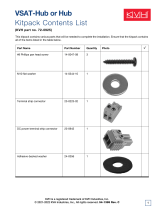
From Cable Wrap
From Azimuth Limit Switch
RFU PCB
From LNB
From Cable Wrap
RFU to CPU
From Antenna Sensor
From Elevation Limit Switch
CPU PCB
From Cable Wrap
From RFU to CPU Cable
From Azimuth Motor
From Elevation Motor
Figure 4-3
PCB Connector Locations
(Rear View)

4. At the azimuth limit switch cover, remove the hot
melt keeping the black and white wires in place
(see Figure 4-7).
5. Remove the three #6-32 x
3
⁄
8" retaining screws from
the limit switch cover and set aside (see
Figure 4-7). Lift the cover to access the limit switch
underneath.
6. Remove the four #8-32 x
1
⁄2" screws securing the
limit switch to the cover and set aside.
7. Replace the azimuth limit switch. Attach the new
switch to the cover using the #8 screws, flat
washers, and cable clamp.
8. Route the new limit switch wires through the
cover and cable clamp to the CPU’s Molex
connector. After noting the position of the old
black and white wires, remove the old wires from
the Molex connector. Attach the new wires in their
place.
9. Before re-installing the azimuth limit switch to the
antenna assembly, orient the switch’s plastic cam
as shown in Figure 4-8 on the following page.
With the cam in the proper position, reinstall the
switch to the antenna assembly using the three #6
retaining screws and flat washers. Ensure the cam
finger engages the stop pin in the mounting cavity.
4
Hot Melt
Retaining Screws
Figure 4-7
Azimuth Limit Switch Cover

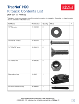
10. Apply hot melt or RTV at the limit switch cover’s
wire access hole to protect the wires from chafing.
5
TracVision 6 Installation and Technical Manual – ADDENDUM
54-0166 Addendum to Rev. B
Plastic Cam
Black and White Wires to
CPU’s Molex Connector
Figure 4-8
Azimuth Limit Switch Orientation

1
TracVision 6 Installation and Technical Manual – ADDENDUM
54-0166 Addendum to Rev. B
TracVision 6 Technical
Manual Addendum
(ECO #5797)
The following changes have been made to Revision B of the
TracVision 6 Installation and Technical Manual (KVH Part
Number 54-0166).
Four fiber shoulder washers have been preinstalled on the inside of the
antenna unit’s base. Four additional fiber shoulder washers have been
provided in the kitpack for use when mounting the antenna unit. These
washers insulate the antenna unit from ground.
2.2 Installing the Antenna Unit
Part Qty.
3
⁄
8-16 x 3" hex screws 4
3
⁄8 flat washers 8
3
⁄8-16 hex nuts 4
3
⁄8 lock washers 4
3
⁄8
fiber shoulder washers 4
#10-32 x
5
⁄8" flat head screws 6
RG-11 type F connector 1
Plastic screw covers 6
Antenna base seal gasket 1
Tie-wraps 2
Core clamp 1
Flash kit cable and adapter 1
Antenna Unit Mounting Procedure
9. Place a flat washer from the kitpack on a bolt and
insert the bolt into its hole from above as shown in
Figure 2-4.
10. Apply a fiber shoulder washer, flat washer, and
lock nut from underneath as shown in Figure 2-4.
Table 2-3
Antenna Unit Kitpack Contents
Figure 2-4
Bolting the Antenna Unit to
the Deck (Side View)
Bolt
Flat Washer
Antenna Unit Base
Foam Seal
Deck
Flat Washer
Lock Nut
Shoulder Washer
Shoulder Washer
(Preinstalled)

1
TracVision 6 Installation and Technical Manual – ADDENDUM
54-0166 Addendum to Rev. B
TracVision 6 Technical
Manual Addendum
(ECO #5503)
The following changes have been made to Revision B of the
TracVision 6 Installation and Technical Manual (KVH Part
Number 54-0166).
4.4 PCB Removal and Replacement
The CPU Printed Circuit Board (PCB) has been changed from an
“L”-shaped design to a simpler straight design. Figure 4-3 has been
updated to show the new CPU PCB.
4.4.1 CPU Board
The new CPU Board is secured to the antenna frame using nine screws
rather than eleven.
2. Remove nine #6-32 machine screws from the PCB.
From Cable Wrap
From Azimuth Limit Switch
RFU PCB
From LNB
From Cable Wrap
RFU to CPU
From Antenna Sensor
From Elevation Limit Switch
CPU PCB
From Cable Wrap
From RFU to CPU Cable
From Azimuth Motor
From Elevation Motor
Figure 4-3
PCB Connector Locations
(Rear View)

1
TracVision 6 Installation and Technical Manual – ADDENDUM
54-0166 Addendum to Rev. B
ECO #5315
TracVision 6 Installation and
Technical Manual Addendum
(ECO #5315)
The following changes have been made to Revision B of the
TracVision 6 Installation and Technical Manual (KVH Part
Number 54-0166).
4.3 TracVision 6 Field
Replaceable Units
The azimuth limit switch has been added to the list of field replaceable
units.
FRU Part Number
Radome 02-1047-01
CPU 02-0992
RF Detector PCB 02-1017-02
Antenna Gyro Sensor 02-1035
Antenna Gyro Gasket 24-0139
Elevation Drive Belt 24-0105-83
Elevation Motor 02-1050
Azimuth Limit Switch Assembly 02-0957-01
European LNB Assembly 02-0932
U.S.-style LNB Assembly 02-0870
Latin American LNB Assembly 02-0870-01
Data Cable 32-0619-100
Switchplate 02-1023
RF Cable 32-0566-0100
PC Cable 32-0628-06
CPU Fuse 16-0017-4000
Table 4-1
TracVision 6 Field
Replaceable Units

4.4 PCB Removal and Replacement
Figure 4-3 has been changed to indicate the correct Molex pin locations
for the azimuth limit switch and the elevation limit switch.
The following procedure has been inserted for replacing the azimuth
limit switch. As a result, Sections 4.6 through 4.8 of the Installation
and Technical Manual have been renumbered Sections 4.7 through 4.9.
4.6 Azimuth Limit Switch Assembly
Replacement
1. Rotate the antenna assembly, by hand, clockwise
until it stops.
2. Remove the printed circuit board (PCB) cover,
illustrated in Figure 4-2, using a #2 Phillips
screwdriver and a
3
⁄
8" nut driver/socket.
3. At the CPU’s Molex connector, cut the black and
white wires from the azimuth limit switch (see
Figure 4-3). Leave about an inch of the wires still
connected for later reference.
4. At the azimuth limit switch cover, remove the hot
melt keeping the black and white wires in place
(see Figure 4-7).
2
From Elevation Motor
From Azimuth Motor
From RFU to CPU Cable
From Cable Wrap
CPU PCB
From Elevation Limit Switch
From Antenna Sensor
From Azimuth Limit Switch
From Cable Wrap
RFU PCB
From LNB
From Cable Wrap
RFU to CPU
Figure 4-3
PCB Connector Locations
(Rear View)

5. Remove the three #6-32 x
3
⁄8" retaining screws from
the limit switch cover and set aside (see Figure
4-7). Lift the cover to access the limit switch
underneath.
6. Remove the four #8-32 x
1
⁄
2" screws securing the
limit switch to the cover and set aside.
7. Replace the azimuth limit switch. Attach the new
switch to the cover using the #8 screws, flat
washers, and cable clamp.
8. Route the new limit switch wires through the
cover and cable clamp to the CPU’s Molex
connector. After noting the position of the old
black and white wires, remove the old wires from
the Molex connector. Attach the new wires in their
place.
9. Before re-installing the azimuth limit switch to the
antenna assembly, orient the switch’s plastic cam
as shown in Figure 4-8 on the following page.
With the cam in the proper position, reinstall the
switch to the antenna assembly using the three #6
retaining screws and flat washers. Ensure the cam
finger engages the stop pin in the mounting cavity.
10. Apply hot melt or RTV at the limit switch cover’s
wire access hole to protect the wires from chafing.
3
TracVision 6 Installation and Technical Manual – ADDENDUM
54-0166 Addendum to Rev. B
ECO #5315
Hot Melt
Retaining Screws
Figure 4-7
Azimuth Limit Switch Cover

4
Plastic Cam
Black and White Wires to
CPU’s Molex Connector
Figure 4-8
Azimuth Limit Switch Orientation

54-0166 Rev. B
TracVision 6 Installation and
Technical Manual
This manual provides detailed instructions on the proper
installation, use, and maintenance of the KVH TracVision 6
automatic satellite tracking system.
Throughout this manual, important information is marked for
your attention by these icons:
Direct questions, comments, or suggestions to:
KVH Industries, Inc. KVH Europe A/S
50 Enterprise Center Ved Klaedebo 12
Middletown, RI 02842 USA 2970 Hoersholm Denmark
tel: +1 401 847-3327 tel: +45 45 16 01 80
fax: +1 401 849-0045 fax: +45 45 86 70 77
internet: http://www.kvh.com internet: http://www.kvh.com
KVH Part # 54-0166 Rev. B
© 2001, KVH Industries, Inc.

TracVision
®
and KVH
®
are registered trademarks
of KVH Industries, Inc.
DIRECTV
®
is an official trademark of DIRECTV, Inc.,
a unit of GM Hughes Electronics.
DISH
™
Network is an official trademark of
EchoStar Communications Corporation.
ExpressVu is a property of Bell ExpressVu, a wholly owned
subsidiary of Bell Satellite Services.
Cetrek
™
is a trademark of Cetrek USA.
Furuno
®
is a registered trademark of Furuno USA, Inc.
B&G
®
and Halcyon
®
are trademarks of Brooks and Gatehouse, Inc.

i
54-0166 Rev. B
Table of Contents
1 TracVision 6 System Overview . . . . . . . . . . . . . . . . . . .1-1
1.1 Materials Provided With TracVision 6 System . . . . . . . . . . . . . .1-2
2 Installation . . . . . . . . . . . . . . . . . . . . . . . . . . . . . . . .2-1
2.1 Choosing the Best Location and Getting
the Best Reception . . . . . . . . . . . . . . . . . . . . . . . . . . . . . . . . . . .2-2
2.2 Installing the Antenna Unit . . . . . . . . . . . . . . . . . . . . . . . . . . . . .2-2
2.2.1 Setting the Skew Angle (European Systems Only) . . . . . . .2-6
2.3 Wiring the TracVision 6 System . . . . . . . . . . . . . . . . . . . . . . . . .2-6
2.3.1 Wiring the Antenna Unit Data Cable . . . . . . . . . . . . . . . . . .2-8
2.3.2 Wiring the Antenna Unit Power Cable . . . . . . . . . . . . . . . . .2-8
2.3.3 Connecting to Ship’s Power . . . . . . . . . . . . . . . . . . . . . . . .2-9
2.3.4 Connecting the IRD Ground Cable . . . . . . . . . . . . . . . . . . .2-9
2.3.5 Installing the Switchplate . . . . . . . . . . . . . . . . . . . . . . . . .2-10
2.3.6 Connecting an Antenna RF Signal Cable to the IRD . . . . .2-10
2.3.6.1 Connecting the Antenna RF Signal Cables
to a Multiswitch (Latin and North American
Systems Only) . . . . . . . . . . . . . . . . . . . . . . . . . . . . . . .2-11
2.4 Commissioning the IRD . . . . . . . . . . . . . . . . . . . . . . . . . . . . . .2-13
2.5 Selecting the Active Satellite . . . . . . . . . . . . . . . . . . . . . . . . . .2-14
2.5.1 Installing Your Selected Satellites . . . . . . . . . . . . . . . . . . .2-15
2.5.2 Programming User-defined Satellites . . . . . . . . . . . . . . . .2-17
2.6 Checking Out the System . . . . . . . . . . . . . . . . . . . . . . . . . . . . .2-21
3 Troubleshooting . . . . . . . . . . . . . . . . . . . . . . . . . . . . .3-1
3.1 Causes and Remedies for Common Operational Issues . . . . . .3-1
3.1.1 Blown Fuse, Low Power, or Wiring . . . . . . . . . . . . . . . . . . .3-2
3.1.2 Vessel Turning During Startup . . . . . . . . . . . . . . . . . . . . . . .3-2
3.1.3 Incorrect Satellite Configuration . . . . . . . . . . . . . . . . . . . . .3-2
3.1.4 Satellite Signal Blocked . . . . . . . . . . . . . . . . . . . . . . . . . . .3-3
3.1.5 Outside Satellite Coverage Zone . . . . . . . . . . . . . . . . . . . .3-3

3.1.6 Radar Interference . . . . . . . . . . . . . . . . . . . . . . . . . . . . . . .3-3
3.1.7 Incorrect or Loose RF Connectors . . . . . . . . . . . . . . . . . . .3-3
3.1.8 Multiswitch Interference (DSS Plus™ IRD Users Only) . . . .3-4
3.1.9 Passive Multiswitch (Latin and North American
Systems Only ) . . . . . . . . . . . . . . . . . . . . . . . . . . . . . . . . . .3-4
3.2 IRD Troubleshooting . . . . . . . . . . . . . . . . . . . . . . . . . . . . . . . . . .3-4
3.3 Antenna Gyro and LNB Faults . . . . . . . . . . . . . . . . . . . . . . . . . .3-4
3.4 Computer Diagnostics . . . . . . . . . . . . . . . . . . . . . . . . . . . . . . . .3-5
3.5 Maintenance Port Parser Commands . . . . . . . . . . . . . . . . . . . . .3-5
4 Maintenance . . . . . . . . . . . . . . . . . . . . . . . . . . . . . . .4-1
4.1 Warranty/Service Information . . . . . . . . . . . . . . . . . . . . . . . . . . .4-1
4.2 Preventive Maintenance . . . . . . . . . . . . . . . . . . . . . . . . . . . . . . .4-1
4.3 TracVision 6 Field Replaceable Units . . . . . . . . . . . . . . . . . . . . .4-2
4.4 PCB Removal and Replacement . . . . . . . . . . . . . . . . . . . . . . . . .4-4
4.4.1 CPU Board . . . . . . . . . . . . . . . . . . . . . . . . . . . . . . . . . . . . .4-5
4.4.2 RF Detector Board . . . . . . . . . . . . . . . . . . . . . . . . . . . . . . .4-5
4.5 Antenna Gyro Assembly . . . . . . . . . . . . . . . . . . . . . . . . . . . . . . .4-6
4.6 Elevation Motor and Belt Replacement . . . . . . . . . . . . . . . . . . .4-8
4.6.1 Drive Belt Removal and Replacement . . . . . . . . . . . . . . . . .4-9
4.6.2 Elevation Drive Motor Removal and Replacement . . . . . . .4-10
4.7 Antenna LNB Replacement . . . . . . . . . . . . . . . . . . . . . . . . . . . .4-10
4.7.1 European LNB Removal . . . . . . . . . . . . . . . . . . . . . . . . . .4-11
4.7.2 U.S. and Latin American-style LNB Replacement . . . . . . .4-11
4.8 Preparation for Shipment . . . . . . . . . . . . . . . . . . . . . . . . . . . . .4-12
Appendix A System Specifications . . . . . . . . . . . . . . . . . .A-1
A.1 Antenna Specifications . . . . . . . . . . . . . . . . . . . . . . . . . . . . . . .A-1
Appendix B Switchplate Template . . . . . . . . . . . . . . . . . .B-1
Appendix C Comprehensive TracVision 6
System Wiring Diagram . . . . . . . . . . . . . . . . .C-1
ii
/