La Cornue G48STANDARD Assembly Instructions
- Category
- Electrical wallplates
- Type
- Assembly Instructions
This manual is also suitable for

Assembly instructions INSTALLATION
Page 28
LA CORNUE
Installation Guide Centenaire
08NOTINSTAL100/USA-2
Château cookers are equipped with adjustable legs so the height of the cooktop can vary from
895 mm (35.24 in) to 915 mm (36.02 in).
Remove the drawers and plinthes/toe-kicks, set the cooker in place, screw up the central legs so
the cooker rests on the outside legs and adjust the height.
Once the cooker is resting at the right height and is level, screw down the central legs to balance
the weight.
USA & CANADA
A
A
SSEMBL
SSEMBL
Y
Y
INSTR
INSTR
UCTIONS
UCTIONS
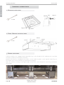
1. HANDRAIL INSTALLATION
2. RISER / BACKSPLASH INSTALLATION
3. HEIGHT ADJUSTMENT
13 mm
8 mm
Support
Plate
M8x20
M8x20
Support
Plate
M5x16
Washer
Inserts

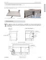
Gas chimney protection plate comes separately in the package and needs to be installed above the
flue channel behind the gas oven.
T
his appliance must be installed by a qualified La Cornue professional in
accordance with the current regulations in the country where the appliance
is installed.
C
C
ONNECTIONS
ONNECTIONS
Electrical
connection
Terminal
Block
Gas Inlet Male
1/2 NPT connection
Rear view Ranges:
Château 90 and Château 75
24“ (620 mm)
2 1/2“ (60 mm)
Electrical
connection
Terminal
Block
Gas Inlet Male
1/2 NPT connection
Rear view Ranges:
Grand Palais 180, Château 165, Château 150 and Château 120
24 “ (620 mm)
2 1/2“ (60 mm)
Side view
All Ranges
Gas Inlet Male
1/2 NPT connection
INSTALLATION Assembly instructions
Page 29
LA CORNUE
Installation Guide Centenaire
08NOTINSTAL100/USA-2
USA & CANADA
4. G
AS CHIMNEY PROTECTION INSTALLATION
Gas oven chimney protection2 x Screw M5 x 16 mm + washer
2” (50 mm)
10 1/2” (265 mm)
Protection Plate
Opening Size 4 3/4” x 7 1/4” (120 x 185 mm)
Gas oven chimney protection

Page 30
LA CORNUE
Installation Guide Centenaire
08NOTINSTAL100/USA-2
USA & CANADA
Electrical connection INSTALLATION
The appliance must be electrically installed and grounded in accordance with local
codes or in the absence of such codes with the latest edition of the "National Electrical
Code", ANSI/NFPA 70 in the USA, and CSA C22.2 "Canadian Electrical Code” - in
Canada.
Disconnect all the power supply circuits before accessing the junction boxes.
This appliance must be supplied with 240 Volt and 60 Hz frequency, and
connected to an individual, properly grounded branch circuit, protected by
a circuit breaker or time-delay fuse, as noted on the rating plate.
Use only a 3-wire or a 4-wire UL-listed power-supply cord rated 120/240
Volts with a straight terminals.
Only a 4 wire cord is to be used when the appliance is installed where
grounding through the neutral conductor is prohibited, such as:
- new branch-circuit installations (1996 NEC),
- mobile homes,
- recreational vehicles or
- in an area where local codes prohibit grounding through the neutral.
The power of the electric elements for each appliance see page 11 and pages 12 - 22.
Wiring must conform to National Electric Codes.
If the electric service provided does not meet the above specifications, have a licensed electrician
install an approved outlet.
Because range terminals are not accessible after range is in position, flexible service conduit or cord
must be used. The range can then be easily disconnected for servicing etc.
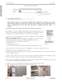
The "La Cornue" appliance is supplied with a connection terminal block accessible by unscrewing
the stainless steel protection plate on the backside.
1. Remove the screws and the protection plate on the backside of the ranges.
For the cooktops remove the cover of the main terminal box.
1. ELECTRICAL CONNECTION
G-Ground N-Neutral
Ph-Phase
Electrical
connection
Terminal
Block
Gas Inlet Male
1/2 NPT connection
1 1/2“ (40 mm)
7 5/8“
(195 mm)
Rear view All Cooktops
Ranges
Cooktops

INSTALLATION Electrical connection
Page 31
LA CORNUE
Installation Guide Centenaire
08NOTINSTAL100/USA-2
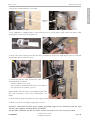
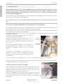
2. Now the terminal block is accessible
3. The appliance is shipped with a strain relief device to secure power cord. Insert the power cord
through the strain relief and tighten it.
4. Insert the strain relief device into the hole and push it to the left. Tight up the power cord and
strain relief device with the screw.
5. Install the power cord: attach the wires to the
terminal block as follows:
- neutral (white wire) to N,
- the L1 and L2 (red and black wire) to P1 and P2,
- the ground to T (yellow / green).
NOTE: Make sure the wires are completely inserted
into the terminals and secure connections are
made.
6. Re-install the protection plate for the range or the cover for the cooktop.
7. Make sure that everything is properly secured.
R
EMINDER: connections to main power supply preferably suppose to be hardwired into the wall
Junction Box compare using the Plugs and Outlet.
Fix the cable well below the hot air outlets, at the rear of the oven, never in front of them.
USA & CANADA
Ranges
Terminal
block
Cooktops

Gas connection INSTALLATION
Page 32
LA CORNUE
Installation Guide Centenaire
08NOTINSTAL100/USA-2
The installation of your La Cornue appliance must conform with local codes or, in the
absence of local codes, in the USA with the "National Fuel Gas Code", ANSI Z223.1, latest
edition, and, in Canada, with CAN/CGA - B149.1, and CAN CGA - B149.2, "Installation Code
for Gas Burning Appliances".
All La Cornue ranges and cooktops are fully assembled and equipped for use with the type of gas
shown on the rating plate of the appliance.
If no special instructions were mentioned upon ordering, the stove is fitted with orifices for natural
gas.
Prior to installation, ensure that the local distribution conditions (nature of the gas and
gas pressure) and the adjustment of the appliance are compatible.
The range is designed to operate at a manifold pressure of 5’’ of Water Column on natural gas, or
a manifold pressure of 11’’ of Water Column on LP gas (Propane).
If the range is to be used on LP gas, a qualified LP installer must convert it. We recommend that
the range be converted before installation.
For proper operation, the pressure of natural gas supplied to the regulator must be between 6’’ and
10’’ of water column.
For LP gas, the pressure supplied must be between
12’’ and 13’’ of water column.
When checking for proper operation of the
regulator, the inlet pressure must be at least 1’’
greater than the operating (manifold) pressure as
given above.
The pressure regulator located at the inlet of the
range manifold must remain in the supply line
regardless of whether natural or LP gas is being
used.
A flexible metal appliance connector used to
connect the range to the gas supply line should
have an I.D. of ½’’ and be 5 feet in length for ease
of installation.
The gas regulator on the appliance is set at the factory for pressures given by regulations.
For the La Cornue ranges and hobs the regulator and the pressure tap can be found on the hob’s
manifold located by the 2 left gas burners
Connect the Range to the Gas Supply
Shut off the main gas supply valve before disconnecting the old
range and leave it off until the new hookup has been
completed. Don’t forget to relight the pilot on other gas
appliances when you turn the gas back on.
Because hard piping restricts movement of the range, the use of
a CSA International certified flexible metal appliance connector
is recommended unless local codes require a hard piped
connection.
2. GAS CONNECTION
USA & CANADA
Pressure
regulator
Pressure
test point
Male threaded fitting,
thread 1/2 NPT
-
 1
1
-
 2
2
-
 3
3
-
 4
4
-
 5
5


La Cornue G48STANDARD Assembly Instructions
- Category
- Electrical wallplates
- Type
- Assembly Instructions
- This manual is also suitable for
Ask a question and I''ll find the answer in the document
Finding information in a document is now easier with AI
Related papers
-
La Cornue G49 Installation guide
-
-
La Cornue G49STANDARD Installation guide
-
La Cornue G45 Installation guide
-
-
GE 1908 - 36" User manual
-
-
-
-
La Cornue C1CF User manual