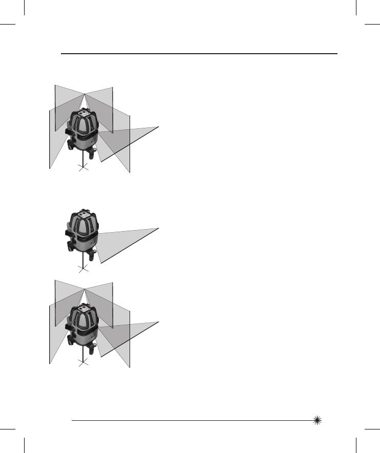
Stanley MULTILINE Owner's manual

Category
Laser levels
Type
Owner's manual

This manual is also suitable for

Please read these instructions before operating the product
MultiLine
5 - Beam Self-Leveling Multi-Line Laser
77-122
Self-Leveling
GB
D
F
I
E
PT
NL
DK
SE
FIN
NO
PL
GR
CZ
RU
HU
SK
SI
BG
RO
EE
LV
TR
LT
HR
2
77-122
Carefully read the Safety Instructions and User Manual before using this product. The person
responsible for the instrument must ensure that all users understand and adhere to these
instructions.
Retain this manual for future reference.
IMPORTANT: The following labels are on your laser tool for your convenience and safety.
They indicate where the laser light is emitted by the level. ALWAYS BE AWARE of their
location when using the level.
1. Safety
2. Product Description
3. Specifications
4. Operating Instructions
5. Calibration
6. Maintenance and Care
7. Warranty
User Safety
Safety
Contents
EN 60825-1
LASER RADIAT I O N - D O N O T
STA RE I NT O BE AM O R V I E W
DIRECTLY W I T H
OPTICAL INSTRUMENTS
CLASS 1M LASER PRODUCT
MAX OUTPUT 1 mW @ 630 - 670 nm
GB
D
F
I
E
PT
NL
DK
SE
FIN
NO
PL
GR
CZ
RU
HU
SK
SI
BG
RO
EE
LV
GB
D
F
I
E
PT
NL
DK
SE
FIN
NO
PL
GR
CZ
RU
HU
SK
SI
BG
RO
EE
LV
TR
GB
D
F
I
E
PT
NL
DK
SE
FIN
NO
PL
GR
CZ
RU
HU
SK
SI
BG
RO
EE
LV
GB ENGLISH
GERMAN
FRENCH
ITALIAN
SPANISH
PORTUGUESE
DUTCH
DANISH
SWEDISH
FINNISH
NORWEGIAN
POLISH
GREEK
CZECH
RUSSIAN
HUNGARIAN
SLOVAKIAN
SLOVENIAN
BULGARIAN
ROMANIAN
ESTONIAN
LATVIAN
LITHUANIAN
TURKISH
CROATIAN
D
F
I
E
PT
NL
DK
SE
FIN
NO
PL
GR
CZ
RU
HU
SK
SI
BG
RO
EE
LV
LT LT LT LT
TR TR TR
HR HR HR HR
3
77-122
DO NOT remove any warning label(s) on the housing. This instrument must only be used for
leveling and layout tasks as outlined in this manual.
ALWAYS make sure that any bystanders in the vicinity of use are made aware of the
dangers of looking directly into the laser tool.
DO NOT use in combination with other optical instruments. Do not modify the instrument, or
make manipulations or use in other applications than those described in the manual.
DO NOT look into the beam with optical aids, such as magnifiers, binoculars or Telescopes.
DO NOT stare into the laser beam or direct it towards other persons. Make sure the
instrument is not set at eye level. Eye protection is normally afforded by natural aversion
responses such as the blink reflex.
DO NOT direct the laser beam at other persons.
ALWAYS turn the laser tool “OFF” when not in use. Leaving the laser tool “ON” increases
the risk of someone inadvertently staring into the laser beam.
DO NOT operate the laser tool in combustible areas such as in the presence of flammable
liquids, gases or dust.
DO NOT disassemble the laser tool. There are no user serviceable parts inside.
Disassembling the laser will void all warranties on the product. Do not modify the product in
any way. Modifying the laser tool may result in hazardous laser radiation exposure.
DO NOT use this instrument in areas where a risk of explosion is present.
NOTE: Since the laser beam is of the focused type, ensure you check the beam’s path over
a relatively long distance and take all necessary precautions to ensure the beam cannot
interfere with other persons.
4
77-122
WARNING: Batteries can explode or leak and can cause injury or fire. To reduce this risk:
ALWAYS follow all instructions and warnings on the battery label and package.
DO NOT short any battery terminals
DO NOT charge alkaline batteries.
DO NOT mix old and new batteries. Replace all of them at the same time with new batteries
of the same brand and type.
DO NOT mix battery chemistries.
DO NOT dispose of batteries in fire.
ALWAYS keep batteries out of reach of children.
ALWAYS remove batteries if the device will not be used for several months.
NOTE: Ensure that the correct batteries as recommended are used.
NOTE: Ensure the batteries are inserted in the correct manner, with the correct polarity.
DO NOT dispose of this product with household waste.
ALWAYS dispose of batteries per local code.
PLEASE RECYCLE in line with local provisions for the collection and disposal of electrical
and electronic waste under the WEEE Directive.
Battery Safety
End of Life
5
77-122
ROHS Compliant
The Stanley Works declares that the CE Mark has been applied to this
product in accordance with the CE Marking Directive 93/68/EEC.
This product conforms with EN60825-1:2007.
For further details please refer to www.stanleyworks.com.
Declaration of Conformity
Product Description
Package Contents
1. Laser Unit
2. IR Remote Controller
3. Laser Target
4. Glasses
5. Carrying Case
6. Batteries (Laser Unit - 4 x AA, IR Remote Controller - 2 x AA)
7. User Manual
EN 60825-1
6
77-122
Product Overview
1. Keyboard
2. Main Power / Transport Lock
3. Fine Tuning Wheel
4. Window for 90° Vertical Reference Beam Laser
5. Window for Front Vertical Beam Laser
6. Window for Horizontal Beam Laser
7. IR Sensor
8. Bubble Level
9. Window for Rear Vertical Beam Laser
10. Laser Warning Label
Battery Compartment Cover
11. Handle
12. Window for 90° Vertical Reference Beam Laser
Laser Unit
13. Adjustable Legs 3x
14. 5/8 - 11 Threaded Mount
Window for Down Beam Laser
IR Remote Controller
14
13
1. IR LED
2. Keyboard
3. Location for Lanyard
4. Battery Compartment Cover
12
9
10
11
2
4
1
3
5
4
1
6
8
2
3
7
7
77-122
Leveling Accuracy:
Down Beam Accuracy:
Square Beam Accuracy:
Horizontal / Vertical Accurracy
Working Range:
Working Distance:
with Laser Detector:
Laser Class:
Laser Wavelength:
Operating Time:
Power Voltage:
Power Supply:
IP Rating:
Operating Temperature Range:
Storage Temperature Range:
Weight (without Base and Batteries):
≤ 2 mm / 10 m (≤ 5/64 in / 30 ft)
≤ 1 mm / 1.5 m (≤ 1/32 in / 5 ft)
≤ 1 mm / 5 m (≤ 1/32 in / 15 ft)
≤ 2 mm / 10 m (≤ 5/64 in / 30 ft)
Self-Leveling to ± 3°
≤ 15 m (≤ 50 ft)
≤ 50 m (≤ 165 ft)
Class 1M
635 nm ± 5 nm
6 h
6 V
4 x AA Batteries (Alkaline)
IP54
-10° C to +40° C (+14° F to +104° F)
-20° C to +60° C (-4° F to +140° F)
980 g (34,5 oz)
Specifications
Laser Unit
8
77-122
110 mm × 105 mm × 180 mm
(4 5/16 in × 4 1/8 in × 7 1/16 in)
Size:
IR Remote Controller
3 V
2 x AA Batteries (Alkaline)
37 g (1,3 oz)
35 mm × 25 mm × 120 mm
(1 3/8 in × 1 in × 4 3/4 in)
Power Voltage:
Power Supply:
Weight (without Batteries):
Size:
9
77-122
Operating Instructions
1. Turn laser unit to back. Open battery
compartment cover by pressing and sliding
out.
2. Install / Remove batteries. Orient batteries
correctly when placing into laser unit.
3. Close and lock battery compartment cover
by sliding in until securely closed.
+
+
+
-
-
-
+
-
Laser Unit
Battery Installation / Removal
10
77-122
4. Press pulse mode key to toggle between
pulse mode ON and OFF. Indicator LED lights
green when on. Pulse mode allows use with
a laser detector.
2. Transport lock in unlocked position. Laser
power is ON. Down laser beam and
horizontal laser beam turn on. Left LED
indicator lights green when laser power is
on.
3. Press laser mode key to toggle through
available laser modes - horizontal only,
both horizontal and vertical, horizontal and
vertical with left and right 90° vertical
reference beam, horizontal with all 4 vertical.
1. Transport lock in locked position. Laser
power is OFF.
5. Laser beam(s) blink to indicate the laser unit
is out of the working range. Reposition laser
unit to be more level.
Pulse Mode
Function
Laser Mode
Unlocked
Locked
11
77-122
8. Low battery - Left LED blinks red to indicate
when battery power is low. Replace
batteries.
Standard Mount for
Optional Tripod Mounting
5/8 in
3. 5/8 - 11 thread mount available for optional
accessories.
Laser Unit Base
1. Turn any of the adjustable legs as needed to
level the laser unit within its workable range.
Use the bubble vial for reference.
2. Use fine adjustment wheel to gradually
rotate the projection of the laser beam(s).
3x
Bubble Vial
12
77-122
IR Remote Controller
Battery Installation / Removal
1. Turn laser unit to back. Open battery
compartment cover by pressing and sliding
out.
2. Install / Remove batteries. Orient batteries
correctly when placing into laser unit.
3. Close and lock battery compartment cover
by sliding in until securely closed.
+
+ -
-
Function
1. Aim remote controller towards laser unit
and press laser mode key to toggle through
available laser modes.
2. Press pulse mode key to toggle between
pulse mode ON and OFF.
Laser Mode
Pulse Mode
13
77-122
Applications
1. Plumb:
Using the vertical laser beam, establish a
vertical reference plane. Position the desired
object(s) until they are aligned with the
vertical reference plane to ensure object(s)
are plumb.
Establish 2 reference points that need to be
plumb. Align either the down laser beam or
the up laser cross to a set reference point.
The opposing laser beam(s) will be projecting
a point which is plumb. Position the desired
object until the laser beam is aligned with
the second reference point that needs to be
plumb with the set reference point.
2. Level:
Using the horizontal laser beam, establish
a horizontal reference plane. Position the
desired object(s) until they are aligned with
the horizontal reference plane to ensure
object(s) are level.
3. Square:
Using either the vertical and horizontal
laser beams with or without the 90° vertical
reference laser beam, establish a point
where the vertical and horizontal beams
cross. Position the desired object(s) until
they are aligned with both the vertical and
horizontal laser beams to ensure object(s)
are square.
4. Pulse Mode:
Setting laser unit to pulse mode allows use
of optional laser detectors.
14
77-122
Calibration
NOTE: The laser unit has been calibrated at the time of manufacturing. Periodically check
the accuracy of the laser unit to ensure that the calibrated specifications are maintained.
P
1
D
1
D
1
2
P
2
P
1
D
1
D
1
2
P
3
P
1
P
2
D
2
P
4
P
1
P
2
P
3
D
2
1. Place laser unit as shown with laser ON.
Mark point P
1
at cross.
Level Beam Accuracy
2. Rotate laser unit 180° and mark point P
2
at cross.
3. Move laser unit close to wall and mark
point P
3
at cross.
4. Rotate laser unit 180° and mark point P
4
at cross.
15
77-122
5. Measure the vertical distance from
the floor to each point. Calculate the
difference between distances D
P1
and D
P3
to get D
3
and distances D
P2
and D
P4
to get
D
4
.
6. Calculate the maximum allowed offset
distance and compare to the difference
of D
3
and D
4
as shown in the equation. If
the sum is not less than or equal to the
calculated maximum offset distance the
unit must be returned to your Stanley
Distributor.
1. Place laser unit as shown with horizontal,
vertical, and both 90° vertical reference
laser beams ON. Mark point P
1
where the
horizontal and left 90° vertical reference
laser beams cross.
Horizontal Beam Accuracy
P
1
D
1
P
3
P
1
D
P3
D
P1
(D
P1
- D
P3
) = D
3
P
4
P
2
D
P2
D
P4
(D
P2
- D
P4
) = D
4
Example: D
1
= 10 m, D
2
= 0,5 m
D
P1
= 30,75 mm, D
P2
= 29 mm, D
P3
= 30 mm, D
P4
= 29,75 mm
D
3
= (30,75 mm - 30 mm) = 0,75 mm
D
4
= (29 mm - 29,75 mm) = - 0,75 mm
0,2 x (10 m - (2 x 0,5 m) = 1,8 mm (maximum allowed offset distance)
(0,75 mm) - (- 0,75 mm) = 1,5 mm
1,5 mm ≤ 1,8 mm (TRUE, unit is within calibration)
mm
m
Compare:
D
3
- D
4
± Max
Maximum Offset Distance:
Max
in
ft
= 0,0024 x (D
1
ft - (2 x D
2
ft))
mm
m
= 0,2 x (D
1
m - (2 x D
2
m))
16
77-122
Example: D
1
= 5 m, D
2
= 1 mm
0,2 x 5 m = 1 mm (maximum allowed offset distance)
1 mm ≤ 1 mm (TRUE, unit is within calibration)
mm
m
2. Rotate laser unit 90° and align front
vertical laser beam with point P
1
. Mark
point P
2
where the horizontal and front
vertical laser beams cross.
3. Rotate laser unit 90° and align right 90°
vertical reference laser beam with point
P
1
. Mark point P
3
where the horizontal and
right 90° vertical reference laser beams
cross.
4. Measure the vertical distance D
2
between
the highest and lowest point
.
P
2
D
1
P
1
P
2
D
1
P
1
P
3
P
2
D
2
P
1
P
3
5. Calculate the maximum allowed offset
distance and compare to D
2
. If D
2
is
not less than or equal to the calculated
maximum offset distance the unit must be
returned to your Stanley Distributor.
Compare:
D
2
Max
Maximum Offset Distance:
Max
in
ft
= 0,0024 x D
1
ft
mm
m
= 0,2 x D
1
m
17
77-122
Vertical Beam Accuracy
P
1
D
1
P
2
P
3
D
1
2 x D
1
P
4
D
1
P
2
P
3
D
1
2 x D
1
P
1
1. Measure the height of a door jamb or
reference point to get distance D
1
. Place
laser unit as shown with laser ON. Aim
vertical beam towards door jamb or
reference point. Mark points P
1
, P
2
, and
P
3
as shown.
Example: D
1
= 2 m, D
2
= 0,5 mm
0,4 x 2 m = 0,8 mm (maximum allowed offset distance)
0,5 mm ≤ 0,8 mm (TRUE, unit is within calibration)
mm
m
2. Move laser unit to opposite side of door
jamb or reference point and align vertical
beam with P
2
and P
3
.
3. Measure the horizontal distances between
P
1
and the vertical beam from the 2nd
location.
4. Calculate the maximum allowed offset
distance and compare to D
2
. If D
2
is
not less than or equal to the calculated
maximum offset distance the unit must be
returned to your Stanley Distributor.
Compare:
D
2
Max
Maximum Offset Distance:
Max
in
ft
= 0,0048 x D
1
ft
mm
m
= 0,4 x D
1
m
P
1
D
2
Vertical
Beam
18
77-122
90° Vertical Beam Accuracy
You will need at least 1,5 m
2
(16 ft
2
) of floor space and possibly an assistant for this check.
1. Place the laser unit on a level floor, and
turn on all beams.
2. Measure exactly 0,91 m (3 ft) out from
the center of the laser unit along the front
vertical laser beam. Mark this point P
1
.
3. Measure exactly 1,22 m (4 ft) out the
center of the instrument along either of
the 90° vertical reference beams, and
mark this point P
2
.
4. Measure from point A to point B; this
distance D
1
should equal 1,522 m ± 0,3 mm
(5 ft ± 1/64 in). If not, the unit must be
returned to your Stanley Distributor.
5. Repeat steps 1 through 4 to check the
other beams.
P
1
0,91 m (3 ft)
P
1
1,22 m (4 ft)
P
2
P
1
P
2
D
1
19
77-122
Laser unit is not waterproof. DO NOT allow to get wet. Damage to internal circuits may
result.
DO NOT leave laser unit in direct sunlight or expose it to high temperatures. The housing
and some internal parts are made of plastic and may become deformed at high temperatures.
DO NOT store the laser unit in a cold environment. Moisture may form on interior parts
when warming up. This moisture could fog up laser windows and cause corrosion of internal
circuit boards.
When working in dusty locations, some dirt may collect on the laser window. Remove any
moisture or dirt with a soft, dry cloth.
DO NOT use aggressive cleaning agents or solvents.
Store the laser unit in its case when not in use. If storing for extended time, remove batteries
before storage to prevent possible damage to the instrument.
Maintenance and Care
20
77-122
One Year Warranty
Stanley Tools warrants its electronic measuring tools against deficiencies in materials and/or
workmanship for one year from date of purchase.
Deficient products will be repaired or replaced, at Stanley Tools’ option, if sent together with
proof of purchase to:
Stanley UK Sales Limited
Gowerton Road
Brackmills, Northampton NN4 7BW
This Warranty does not cover deficiencies caused by accidental damage, wear and tear, use
other than in accordance with the manufacturer’s instructions or repair or alteration of this
product not authorised by Stanley Tools.
Repair or replacement under this Warranty does not affect the expiry date of the Warranty.
To the extent permitted by law, Stanley Tools shall not be liable under this Warranty for
indirect or consequential loss resulting from deficiencies in this product.
This Warranty may not be varied without the authorisation of Stanley Tools.
This Warranty does not affect the statutory rights of consumer purchasers of this product.
This Warranty shall be governed by and construed in accordance with the laws of England
and Stanley Tools and the purchaser each irrevocably agrees to submit to the exclusive
jurisdiction of the courts of England over any claim or matter arising under or in connection
with this Warranty.
IMPORTANT NOTE: The customer is responsible for the correct use and care of the
instrument. Moreover, the customer is completely responsible for periodically checking the
accuracy of the laser unit, and therefore for the calibration of the instrument.
Calibration and care are not covered by warranty.
Subject to change without notice
Warranty
  • Page 1 1
  • Page 2 2
  • Page 3 3
  • Page 4 4
  • Page 5 5
  • Page 6 6
  • Page 7 7
  • Page 8 8
  • Page 9 9
  • Page 10 10
  • Page 11 11
  • Page 12 12
  • Page 13 13
  • Page 14 14
  • Page 15 15
  • Page 16 16
  • Page 17 17
  • Page 18 18
  • Page 19 19
  • Page 20 20
  • Page 21 21
  • Page 22 22
  • Page 23 23
  • Page 24 24
  • Page 25 25
  • Page 26 26
  • Page 27 27
  • Page 28 28
  • Page 29 29
  • Page 30 30
  • Page 31 31
  • Page 32 32
  • Page 33 33
  • Page 34 34
  • Page 35 35
  • Page 36 36
  • Page 37 37
  • Page 38 38
  • Page 39 39
  • Page 40 40
  • Page 41 41
  • Page 42 42
  • Page 43 43
  • Page 44 44
  • Page 45 45
  • Page 46 46
  • Page 47 47
  • Page 48 48
  • Page 49 49
  • Page 50 50
  • Page 51 51
  • Page 52 52
  • Page 53 53
  • Page 54 54
  • Page 55 55
  • Page 56 56
  • Page 57 57
  • Page 58 58
  • Page 59 59
  • Page 60 60
  • Page 61 61
  • Page 62 62
  • Page 63 63
  • Page 64 64
  • Page 65 65
  • Page 66 66
  • Page 67 67
  • Page 68 68
  • Page 69 69
  • Page 70 70
  • Page 71 71
  • Page 72 72
  • Page 73 73
  • Page 74 74
  • Page 75 75
  • Page 76 76
  • Page 77 77
  • Page 78 78
  • Page 79 79
  • Page 80 80
  • Page 81 81
  • Page 82 82
  • Page 83 83
  • Page 84 84
  • Page 85 85
  • Page 86 86
  • Page 87 87
  • Page 88 88
  • Page 89 89
  • Page 90 90
  • Page 91 91
  • Page 92 92
  • Page 93 93
  • Page 94 94
  • Page 95 95
  • Page 96 96
  • Page 97 97
  • Page 98 98
  • Page 99 99
  • Page 100 100
  • Page 101 101
  • Page 102 102
  • Page 103 103
  • Page 104 104
  • Page 105 105
  • Page 106 106
  • Page 107 107
  • Page 108 108
  • Page 109 109
  • Page 110 110
  • Page 111 111
  • Page 112 112
  • Page 113 113
  • Page 114 114
  • Page 115 115
  • Page 116 116
  • Page 117 117
  • Page 118 118
  • Page 119 119
  • Page 120 120
  • Page 121 121
  • Page 122 122
  • Page 123 123
  • Page 124 124
  • Page 125 125
  • Page 126 126
  • Page 127 127
  • Page 128 128
  • Page 129 129
  • Page 130 130
  • Page 131 131
  • Page 132 132
  • Page 133 133
  • Page 134 134
  • Page 135 135
  • Page 136 136
  • Page 137 137
  • Page 138 138
  • Page 139 139
  • Page 140 140
  • Page 141 141
  • Page 142 142
  • Page 143 143
  • Page 144 144
  • Page 145 145
  • Page 146 146
  • Page 147 147
  • Page 148 148
  • Page 149 149
  • Page 150 150
  • Page 151 151
  • Page 152 152
  • Page 153 153
  • Page 154 154
  • Page 155 155
  • Page 156 156
  • Page 157 157
  • Page 158 158
  • Page 159 159
  • Page 160 160
  • Page 161 161
  • Page 162 162
  • Page 163 163
  • Page 164 164
  • Page 165 165
  • Page 166 166
  • Page 167 167
  • Page 168 168
  • Page 169 169
  • Page 170 170
  • Page 171 171
  • Page 172 172
  • Page 173 173
  • Page 174 174

Stanley MULTILINE Owner's manual

Category
Laser levels
Type
Owner's manual
This manual is also suitable for

Ask a question and I''ll find the answer in the document

Finding information in a document is now easier with AI