12
77-122
13
77-122
Applications
1. Plumb:
Using the vertical laser beam, establish a
vertical reference plane. Position the desired
object(s) until they are aligned with the
vertical reference plane to ensure object(s)
are plumb.
Establish 2 reference points that need to be
plumb. Align either the down laser beam or
the up laser cross to a set reference point.
The opposing laser beam(s) will be projecting
a point which is plumb. Position the desired
object until the laser beam is aligned with
the second reference point that needs to be
plumb with the set reference point.
2. Level:
Using the horizontal laser beam, establish
a horizontal reference plane. Position the
desired object(s) until they are aligned with
the horizontal reference plane to ensure
object(s) are level.
3. Square:
Using either the vertical and horizontal
laser beams with or without the 90° vertical
reference laser beam, establish a point
where the vertical and horizontal beams
cross. Position the desired object(s) until
they are aligned with both the vertical and
horizontal laser beams to ensure object(s)
are square.
4. Pulse Mode:
Setting laser unit to pulse mode allows use
of optional laser detectors.
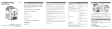
IR Remote Controller
Battery Installation / Removal
1. Turn laser unit to back. Open battery
compartment cover by pressing and sliding
out.
2. Install / Remove batteries. Orient batteries
correctly when placing into laser unit.
3. Close and lock battery compartment cover
by sliding in until securely closed.
+
+ -
-
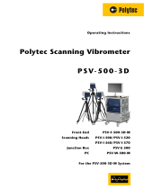
Function
1. Aim remote controller towards laser unit
and press laser mode key to toggle through
available laser modes.
2. Press pulse mode key to toggle between
pulse mode ON and OFF.
Laser Mode
Pulse Mode