ESAB Migmaster 275 Welding Package User manual
- Category
- Welding System
- Type
- User manual

Instruction Manual
0558008552 07 / 2009
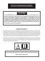
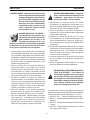
Welding Package
Migmaster 275
OPTIONAL
DIGITAL METER
MODULE
OPTIONAL
BURN BACK
MODULE

2
This equipment will perform in conformity with the description thereof contained in this manual and accompa-
nying labels and/or inserts when installed, operated, maintained and repaired in accordance with the instruc-
tions provided. This equipment must be checked periodically. Malfunctioning or poorly maintained equipment
should not be used. Parts that are broken, missing, worn, distorted or contaminated should be replaced imme-
diately. Should such repair or replacement become necessary, the manufacturer recommends that a telephone
or written request for service advice be made to the Authorized Distributor from whom it was purchased.
This equipment or any of its parts should not be altered without the prior written approval of the manufacturer.
The user of this equipment shall have the sole responsibility for any malfunction which results from improper
use, faulty maintenance, damage, improper repair or alteration by anyone other than the manufacturer or a ser-
vice facility designated by the manufacturer.
BE SURE THIS INFORMATION REACHES THE OPERATOR.
YOU CAN GET EXTRA COPIES THROUGH YOUR SUPPLIER.
These INSTRUCTIONS are for experienced operators. If you are not fully familiar with the
principles of operation and safe practices for arc welding and cutting equipment, we urge
you to read our booklet, “Precautions and Safe Practices for Arc Welding, Cutting, and
Gouging,” Form 52-529. Do NOT permit untrained persons to install, operate, or maintain
this equipment. Do NOT attempt to install or operate this equipment until you have read
and fully understand these instructions. If you do not fully understand these instructions,
contact your supplier for further information. Be sure to read the Safety Precautions be-
fore installing or operating this equipment.
CAUTION
USER RESPONSIBILITY
READ AND UNDERSTAND THE INSTRUCTION MANUAL BEFORE INSTALLING OR OPERATING.
PROTECT YOURSELF AND OTHERS!

3
TABLE OF CONTENT
SECTION NO. .......................................................................................................................................................PAGE NO.
SECTION 1 - SAFETY PRECAUTIONS ...............................................................................................................................5
SECTION 2 - INTRODUCTION ..........................................................................................................................................17
2.1 GENERAL ........................................................................................................................................................................................................17
2.2 RECEIVING-HANDLING ..............................................................................................................................................................................17
2.3 DESCRIPTION, Available Packages/Contents ....................................................................................................................................17
2.4 OPTIONAL ACCESSORIES .........................................................................................................................................................................18
2.5 MIGMASTER 275 / GUNMASTER 250 WEAR PARTS .........................................................................................................................19
SECTION 3 - INSTALLATION ............................................................................................................................................21
3.1 LOCATION ......................................................................................................................................................................................................21
3.2 ELECTRICAL INPUT CONNECTIONS ......................................................................................................................................................21
3.3 SECONDARY OUTPUT CONNECTIONS .................................................................................................................................................24
3.4 TORCH CONNECTIONS ..............................................................................................................................................................................25
3.5 WIRE FEEDER MECHANISM ......................................................................................................................................................................25
3.6 CONNECTION OF THE SHIELD GAS .......................................................................................................................................................26
3.7 WELDING CABLE CONNECTIONS ..........................................................................................................................................................26
3.8 INSTALLING OPTIONAL BURN BACK MODULE .................................................................................................................................27
3.9 INSTALLING OPTIONAL DIGITAL METER .............................................................................................................................................27
SECTION 4 - OPERATION .................................................................................................................................................29
4.1 CONTROLS .....................................................................................................................................................................................................29
4.2 PROCESS SETUP ...........................................................................................................................................................................................31
4.3 OPERATING SAFETY PROCEDURES .......................................................................................................................................................32
SECTION 5 - SERVICE ......................................................................................................................................................37
5.1 MAINTENANCE .............................................................................................................................................................................................37
5.2 INSPECTION AND SERVICE.......................................................................................................................................................................37
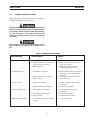
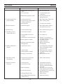
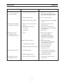
5.3 TROUBLESHOOTING ..................................................................................................................................................................................38
SECTION 6 - REPLACEMENT PARTS ................................................................................................................................43
6.1 GENERAL ........................................................................................................................................................................................................43
6.2 ORDERING .....................................................................................................................................................................................................43

4
TABLE OF CONTENT

5
SECTION 1 SAFETY PRECAUTIONS
1.0 Safety Precautions
1.1 Safety - English
WARNING: These Safety Precautions are
for your protection. They summarize pre-
cautionary information from the references
listed in Additional Safety Information sec-
tion. Before performing any installation or operating
procedures, be sure to read and follow the safety precau-
tions listed below as well as all other manuals, material
safety data sheets, labels, etc. Failure to observe Safety
Precautions can result in injury or death.
PROTECT YOURSELF AND OTHERS --
Some welding, cutting, and gouging
processes are noisy and require ear
protection. The arc, like the sun, emits
ultraviolet (UV) and other radiation
and can injure skin and eyes. Hot metal can cause
burns. Training in the proper use of the processes
and equipment is essential to prevent accidents.
Therefore:
1. Always wear safety glasses with side shields in any
work area, even if welding helmets, face shields, and
goggles are also required.
2. Use a face shield tted with the correct lter and
cover plates to protect your eyes, face, neck, and
ears from sparks and rays of the arc when operating
or observing operations. Warn bystanders not to
watch the arc and not to expose themselves to the
rays of the electric-arc or hot metal.
3. Wear ameproof gauntlet type gloves, heavy long-
sleeve shirt, cuess trousers, high-topped shoes,
and a welding helmet or cap for hair protection, to
protect against arc rays and hot sparks or hot metal.
A ameproof apron may also be desirable as protec-
tion against radiated heat and sparks.
4. Hot sparks or metal can lodge in rolled up sleeves,
trouser cus, or pockets. Sleeves and collars should
be kept buttoned, and open pockets eliminated from
the front of clothing.
5. Protect other personnel from arc rays and hot
sparks with a suitable non-ammable partition or
curtains.
6. Use goggles over safety glasses when chipping slag
or grinding. Chipped slag may be hot and can y far.
Bystanders should also wear goggles over safety
glasses.
FIRES AND EXPLOSIONS -- Heat from
ames and arcs can start res. Hot
slag or sparks can also cause res and
explosions. Therefore:
1. Remove all combustible materials well away from
the work area or cover the materials with a protec-
tive non-ammable covering. Combustible materials
include wood, cloth, sawdust, liquid and gas fuels,
solvents, paints and coatings, paper, etc.
2. Hot sparks or hot metal can fall through cracks or
crevices in oors or wall openings and cause a hid-
den smoldering re or res on the oor below. Make
certain that such openings are protected from hot
sparks and metal.“
3. Do not weld, cut or perform other hot work until the
workpiece has been completely cleaned so that there
are no substances on the workpiece which might
produce ammable or toxic vapors. Do not do hot
work on closed containers. They may explode.
4. Have re extinguishing equipment handy for instant
use, such as a garden hose, water pail, sand bucket,
or portable re extinguisher. Be sure you are trained
in its use.
5. Do not use equipment beyond its ratings. For ex-
ample, overloaded welding cable can overheat and
create a re hazard.
6. After completing operations, inspect the work area
to make certain there are no hot sparks or hot metal
which could cause a later re. Use re watchers when
necessary.
7. For additional information, refer to NFPA Standard
51B, "Fire Prevention in Use of Cutting and Welding
Processes", available from the National Fire Protec-
tion Association, Batterymarch Park, Quincy, MA
02269.
ELECTRICAL SHOCK -- Contact with
live electrical parts and ground can
cause severe injury or death. DO NOT
use AC welding current in damp areas,
if movement is conned, or if there is
danger of falling.

6
SECTION 1 SAFETY PRECAUTIONS
1. Be sure the power source frame (chassis) is con-
nected to the ground system of the input power.
2. Connect the workpiece to a good electrical
ground.
3. Connect the work cable to the workpiece. A poor
or missing connection can expose you or others
to a fatal shock.
4. Use well-maintained equipment. Replace worn or
damaged cables.
5. Keep everything dry, including clothing, work
area, cables, torch/electrode holder, and power
source.
6. Make sure that all parts of your body are insulated
from work and from ground.
7. Do not stand directly on metal or the earth while
working in tight quarters or a damp area; stand
on dry boards or an insulating platform and wear
rubber-soled shoes.
8. Put on dry, hole-free gloves before turning on the
power.
9. Turn o the power before removing your gloves.
10. Refer to ANSI/ASC Standard Z49.1 (listed on
next page) for specic grounding recommenda-
tions. Do not mistake the work lead for a ground
cable.
ELECTRIC AND MAGNETIC FIELDS
— May be dangerous. Electric cur-
rent owing through any conduc-
tor causes localized Electric and
Magnetic Fields (EMF). Welding and
cutting current creates EMF around welding cables
and welding machines. Therefore:
1. Welders having pacemakers should consult their
physician before welding. EMF may interfere with
some pacemakers.
2. Exposure to EMF may have other health eects which
are unknown.
3. Welders should use the following procedures to
minimize exposure to EMF:
A. Route the electrode and work cables together.
Secure them with tape when possible.
B. Never coil the torch or work cable around your
body.
C. Do not place your body between the torch and
work cables. Route cables on the same side of
your body.
D. Connect the work cable to the workpiece as close
as possible to the area being welded.
E. Keep welding power source and cables as far
away from your body as possible.
FUMES AND GASES -- Fumes and
gases, can cause discomfort or harm,
particularly in conned spaces. Do
not breathe fumes and gases. Shield-
ing gases can cause asphyxiation.
Therefore:
1. Always provide adequate ventilation in the work area
by natural or mechanical means. Do not weld, cut, or
gouge on materials such as galvanized steel, stain-
less steel, copper, zinc, lead, beryllium, or cadmium
unless positive mechanical ventilation is provided.
Do not breathe fumes from these materials.
2. Do not operate near degreasing and spraying opera-
tions. The heat or arc rays can react with chlorinated
hydrocarbon vapors to form phosgene, a highly
toxic gas, and other irritant gases.
3. If you develop momentary eye, nose, or throat ir-
ritation while operating, this is an indication that
ventilation is not adequate. Stop work and take
necessary steps to improve ventilation in the work
area. Do not continue to operate if physical discom-
fort persists.
4. Refer to ANSI/ASC Standard Z49.1 (see listing below)
for specic ventilation recommendations.

7
SECTION 1 SAFETY PRECAUTIONS
5. WARNING: This product, when used for welding
or cutting, produces fumes or gases
which contain chemicals known to
the State of California to cause birth
defects and, in some cases, cancer.
(California Health & Safety Code
§25249.5 et seq.)
CYLINDER HANDLING -- Cylinders,
if mishandled, can rupture and vio-
lently release gas. Sudden rupture
of cylinder, valve, or relief device can
injure or kill. Therefore:
1. Use the proper gas for the process and use the
proper pressure reducing regulator designed to
operate from the compressed gas cylinder. Do not
use adaptors. Maintain hoses and ttings in good
condition. Follow manufacturer's operating instruc-
tions for mounting regulator to a compressed gas
cylinder.
2. Always secure cylinders in an upright position by
chain or strap to suitable hand trucks, undercar-
riages, benches, walls, post, or racks. Never secure
cylinders to work tables or xtures where they may
become part of an electrical circuit.
3. When not in use, keep cylinder valves closed. Have
valve protection cap in place if regulator is not con-
nected. Secure and move cylinders by using suitable
hand trucks. Avoid rough handling of cylinders.
4. Locate cylinders away from heat, sparks, and ames.
Never strike an arc on a cylinder.
5. For additional information, refer to CGA Standard P-1,
"Precautions for Safe Handling of Compressed Gases
in Cylinders", which is available from Compressed
Gas Association, 1235 Jeerson Davis Highway,
Arlington, VA 22202.
EQUIPMENT MAINTENANCE -- Faulty or
improperly maintained equipment can
cause injury or death. Therefore:
1. Always have qualied personnel perform the instal-
lation, troubleshooting, and maintenance work.
Do not perform any electrical work unless you are
qualied to perform such work.
2. Before performing any maintenance work inside a
power source, disconnect the power source from
the incoming electrical power.
3. Maintain cables, grounding wire, connections, power
cord, and power supply in safe working order. Do
not operate any equipment in faulty condition.
4. Do not abuse any equipment or accessories. Keep
equipment away from heat sources such as furnaces,
wet conditions such as water puddles, oil or grease,
corrosive atmospheres and inclement weather.
5. Keep all safety devices and cabinet covers in position
and in good repair.
6. Use equipment only for its intended purpose. Do
not modify it in any manner.
ADDITIONAL SAFETY INFORMATION -- For
more information on safe practices for
electric arc welding and cutting equip-
ment, ask your supplier for a copy of
"Precautions and Safe Practices for Arc
Welding, Cutting and Gouging", Form
52-529.
The following publications, which are available from
the American Welding Society, 550 N.W. LeJuene Road,
Miami, FL 33126, are recommended to you:
1. ANSI/ASC Z49.1 - "Safety in Welding and Cutting"
2. AWS C5.1 - "Recommended Practices for Plasma Arc
Welding"
3. AWS C5.2 - "Recommended Practices for Plasma Arc
Cutting"
4. AWS C5.3 - "Recommended Practices for Air Carbon
Arc Gouging and Cutting"

8
SECTION 1 SAFETY PRECAUTIONS
5. AWS C5.5 - "Recommended Practices for Gas Tung-
sten Arc Welding“
6. AWS C5.6 - "Recommended Practices for Gas Metal
Arc Welding"“
7. AWS SP - "Safe Practices" - Reprint, Welding Hand-
book.
8. ANSI/AWS F4.1, "Recommended Safe Practices for
Welding and Cutting of Containers That Have Held
Hazardous Substances."
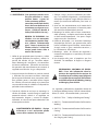
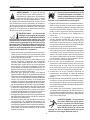
MEANING OF SYMBOLS - As used
throughout this manual: Means Atten-
tion! Be Alert! Your safety is involved.
Means immediate hazards which,
if not avoided, will result in im-
mediate, serious personal injury
or loss of life.
Means potential hazards which
could result in personal injury or
loss of life.
Means hazards which could result
in minor personal injury.
Page is loading ...
Page is loading ...
Page is loading ...
Page is loading ...
Page is loading ...
Page is loading ...
Page is loading ...
Page is loading ...

17
SECTION 2 INTRODUCTION
2.1 GENERAL
This manual has been prepared for use in familiarizing per-
sonnel with the safe installation, operation, maintenance,
and troubleshooting of this equipment. All information
presented here in must be given careful consideration to
assure safe operation and use of this equipment.
2.2 RECEIVING-HANDLING
Upon receipt, carefully inspect for damage that may have
occurred during shipment. Claims for loss or damage that
may have occurred in transit must be led by the purchaser
with the carrier. A copy of the bill of lading and freight bill
will be furnished by the carrier on request.
When requesting information concerning this equipment,
Part number, Serial number and Model name will be required.
Please take a few moments now to record the information
in the box below for future reference.
Date / /
Model Name
Stock Number
Serial Number
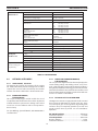
2.3 DESCRIPTION
The Migmaster 275 self contained welding system is designed
to deliver superior performance using short arc, spray arc, as
well as ux and metal cored wires ranging from .023 (.6mm),
to 1/16" (1.6mm) diameter.
The unit consists of a tapped single phase power section
with a built in wire feeder and is supplied as a ready to weld
package. It utilizes a dual groove feed roll and is capable of
40 to 750 Inches Per Minute wire speed.
An Esab GunMaster 250, lightweight air cooled welding gun
included in select systems is supplied complete and ready
to weld 0.035 / 0.045 in. steel wire.
Quick connect output receptacles provide for easy polar-
ity reversal as well connection point for an optional Spool
Gun.
The built in Spool Gun Control can be used to weld hard
and aluminum wire with an optional MT-250SG or ST-23A
spool-guns.
The built in running gear assures convienent shop mobility
and features a cylinder tray and support.
2.3.1 AVAILABLE PACKAGES AND CONTENTS
Migmaster
®
275 Packages
Each of the following packages includes power source with built-in wire
feeder, factory-installed undercarriage with cylinder tray, GunMaster
NAS Mig gun with .035 in. and .045 in. accessories, dual groove (.035 in.
– .045 in.) feed roll, R-33 owmeter-regulator, 6 ft. gas hose, 15 ft. work
cable and clamp, 8 ft. primary input cable with plug, 10 lb. sample of .035
ESAB Spoolarc 87HP welding wire, and an ESAB Mig Welding Handbook.
Migmaster
®
275 Package w/12 ft. GM-250 NAS Torch/Argon
208/230 vac, 1 phase, 60 Hz .................................................. 0558008708
208-575 vac multi-voltage*, 1 phase, 50/60 Hz ............. 0558008709
Migmaster
®
275 Package w/15 ft. GM-250 NAS Torch/Argon
208/230 vac, 1 phase, 60 Hz ...................................................0558008707
208-575 vac multi-voltage*, 1 phase, 50/60 Hz ..............0558008710
Migmaster
®
275 Package w/15 ft. GM-400 NAS Torch/Argon
208/230 vac, 1 phase, 60 Hz ...................................................0558008711
Migmaster
®
275 Package w/o Torch/Argon
208/230 vac, 1 phase, 60 Hz ...................................................0558008714
Migmaster
®
275 Packages with Spool-On-Gun
Spool-On-Gun Packages also include the indicated spool gun and all
components necessary to install it on the Migmaster
®
250. The spool gun
is set up to run 3/64 in. wire.
Migmaster
®
275 Package w/15 ft. GM-250 NAS Torch
and MT-250SG / Argon
208/230 vac, 1 phase, 60 Hz ...................................................0558008712
Migmaster
®
275 Package w/15 ft. GM-250 NAS Torch
and ST-23A / Argon
208/230 vac, 1 phase, 60 Hz ...................................................0558008713
Special Order
Migmaster
®
275 for use with MIG-41A Push-Pull Gun
Push-Pull Ready console is set up to accept the ESAB MIG-41A Push-Pull
gun (order gun, gun ttings and package accessories separately)
Migmaster
®
275 console with Push-Pull Module Installed
208/230 vac, 1 phase, 60 Hz ...................................................0558008621
208-575 vac multi-voltage*, 1 phase, 50/60 Hz ............. 0558008622
Complete Product, Ordering, and Accessory information can be found in
the Sales Data Page ARC-23244 or on the World Wide Web at
www.esabna.com.
*Multi-Voltage model: 208/230/380/400/460/575 (60Hz) vac and 380/400 (50Hz) vac.
*Multi-Voltage model: 208/230/380/400/460/575 (60Hz) vac and 380/400 (50Hz) vac.

18
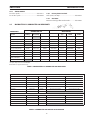
SECTION 2 INTRODUCTION
POWER SOURCE
MIGMASTER-275
Primary Input -Single Phase 208/230/380/400/460/575 Vac
Rated Output 275 Amps @ 28V
Output Current / Voltage Range 30 A/12V - 300A/30V
Maximum Open Circuit Volts 55 Vdc
Duty Cycle:
208/230V Unit 40% 275 Amps @ 28 Vdc
60% 250 Amps @ 26 Vdc
100% 200 Amps @ 24 Vdc
Duty Cycle:
208/230/460/575 Unit
380/400 Unit
35% 275 Amps @ 28 Vdc
60% 225 Amps @ 25 Vdc
100% 180 Amps @ 23 Vdc
Primary 60 HZ Input (Amps):
208/230 Unit
208/230/460/575 Unit
66/61 Amps
66/61/30/25 Amps
Primary 50 HZ Input (Amps):
380/400 37/36 Amps
FEEDER Feed Type/Speed Range Push Type - 40 to 750 IPM (1 - 16.3 m/min.)
Wire Sizes: Hard 0.023" (0.6mm) through 0.045" (1.2mm)
Cored 0.035" (0.9mm) through 1/16" (1.6mm)
Soft 3/64" (1.2mm) and 1/16" (1.6mm)
Welding Gun Cooling Air
GunMaster-250 Gooseneck Angle 45 degrees
Rated 60% Duty Cycle (DCEP) 200 Amps Argon Mixtures, 300 Amps CO2
Conduit Length Available in 10, 12, and 15 ft. - See Section 2.3.2
Physical Net Weight *210 lbs (95 Kg.)
*Includes running gear Height *32.25 inches (819 mm)
& cylinder tray. Width *19.5 inches (495 mm)
Depth *40.0 inches (1016 mm)
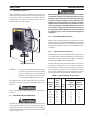
2.4 OPTIONAL ACCESSORIES
2.4.1 AUTO-FAN KIT, P/N 16781
The Auto-Fan kit controls the operation of the cooling
fan. It will automatically turn the cooling fan on and o as
required. This serves to reduce overall shop noise and the
amount of air-bourne debris that is drawn into the unit.
2.4.2 BURN BACK MODULE,
P/N 0558008623.
This easy-to-install, plug-in module enables the use of
an adjustable Anti-Stick feature that allows adjustment
of burnback time to prevent wire sticking at the end of
a weld. See Sec 3.8 Installation and Sec. 4.2 Operation -
Process Setup.
For Spot Welding, Spotweld Nozzle, P/N 0885001602 is
recommended.
2.4.3 DIGITAL VOLT/AMMETER MODULE,
P/N 0558008585.
This easy-to-install digital meter kit alternately displays the
actual welding voltage and welding current every 4-sec-
onds. L.E.D.’s below the meter indicate which condition is
being displayed. After the torch trigger is released, the meter
will continue to ash for 20-seconds the last condition used
during welding. At the end of this time, the meter will reset
to zero. See Section 3.9 Installation.
2.4.4 MT-250SG and ST-23A SPOOL GUN
The Migmaster 275 unit is equipped with a built-in control
that accepts the MT-250SG or ST-23A spool gun. These
air cooled spool guns are designed for mig welding with
soft wires. They are completely portable up to 25-ft. and
weigh less than three (3) pounds. See 4.2.2 Installation/
Operation.
MT-250SG Spool Gun ................................................P/N 36779
Instruction Literature ........................................................F15-380
ST-23A Spool Gun .......................................................P/N 19164
Requires Adaptor ................................................................... 37301
Instruction Literature ........................................................F14-353
TABLE 2.1 SPECIFICATIONS

19
SECTION 2 INTRODUCTION
GUNMASTER-250 STANDARD DUTY NOZZLES & TIP ADAPTER w/ Std Contact Tips w/ HD Contact Tips
3/8" Nozzle 0558001609 COPPER Flush with nozzle Recessed 1/8" into nozzle
1/2" Nozzle 0558001612 COPPER Recessed 1/8" into nozzle Flush with nozzle
1/2" Nozzle 0558001611 COPPER Flush with nozzle Extends1/8" out of nozzle
1/2" Nozzle 0558001613 COPPER Extends1/8" out of nozzle Extends1/4" out of nozzle
5/8" Nozzle 0558001614 COPPER Flush with nozzle Extends1/8" out of nozzle
5/8" Nozzle 0558001615 COPPER Extends1/8" out of nozzle Extends1/4" out of nozzle
SPOT Nozzle 0558001602 BRASS Recessed 3/8" into nozzle Recessed 3/8" into nozzle
Tip/Nozzle Adapter 0558001608 BRASS
GUNMASTER-250 HEAVY DUTY NOZZLES & TIP ADAPTER w/ Std Contact Tips w/ HD Contact Tips
5/8" Nozzle 0558001599 COPPER Recessed 1/8" into nozzle Flush with nozzle
5/8" Nozzle 0558001600 COPPER Recessed 1/4" into nozzle Recessed 1/8" into nozzle
5/8" Nozzle 0558001598 COPPER Flush with nozzle Extends1/8" out of nozzle
SPOT Nozzle 0558001602 BRASS Recessed 3/8" into nozzle Recessed 1/4" into nozzle
Tip/Nozzle Adapter 0558001888 BRASS
2.4.5 SPOOL SPACER
For 8" dia. spools .........................................................P/N 17511
For 10" dia. spools ......................................................P/N 34330
TABLE 2.2 MIGMASTER 275 / GUNMASTER 250 WEAR PARTS
TABLE 2.3 GUNMASTER 250 NOZZLES & TIP ADAPTER
WEAR PARTS GUNMASTER 250 WIRE FEEDER
Wire Size
Contact Tip
Std Duty
Contact Tip
Heavy Duty
Liner *
DRIVE ROLL Groove
Type
OUTLET
GUIDE
INLET
GUIDE
.023" (0.6MM) Hard
20543 0558001675 0558008700 V- Solid 0558008651 23612461
.030"(0.8mm) Hard
20544 0558002367 37031 0558008700 V- Solid 0558008651 23612461
.035" (0.9mm) Hard
996995 0558002368 37032 0558008536 V- Solid 0558008650 34615
.040" (1.0mm) Hard
0558002369 37032 0558008536 V- Solid 0558008650 34615
.045" (1.2mm) Hard
37290 37286 37032 0558008536 V- Solid 0558008650 34615
.035" (0.9mm) Cored
996995 0558002368 37032 0558008540 K- Cored 0558008650 34615
.045" (1.2mm) Cored
37290 37286 37032 0558008540 K- Cored 0558008650 34615
.052" (1.4mm) Cored
2075349 17778 37033 0558008541 K- Cored 0558008649 0558001758
.062" (1.6mm) Cored
996997 37291 37033 0558008541 K- Cored 0558008649 0558001758
3/64" (1.2mm) AL
996999 17765 37034** 0558008538 U - Soft 0558008654 23612461
1/16" (1.6mm) AL
948835 37040** 0558008538 U - Soft 0558008654 23612461
* All Liners supplied 15 ft. and must be trimmed to t the gun per instructions.
** Requires Jumper Liner Sleeve 0558003050
Bold indicates "as supplied from factory".
2.4.6 Primary Extension Cord
25 ft. (9.5m) / 50 Amp ..................................................P/N 37833
2.4.7 Gas Meter
Measures shield gas ow at the nozzle .................P/N 19043
2.5 MIGMASTER 275 / GUNMASTER 250 WEAR PARTS

20
SECTION 2 INTRODUCTION

21
Before making electrical input connections to the weld-
ing machine, “Machinery Lockout Procedures” must be
employed. If the connections are to be made from a line
disconnect switch, the switch must be padlocked in the
o position. If the connection is made from a fusebox,
remove the fuses from the box and padlock the cover
in the closed position. If locking facilities are not avail-
able, attach a red tag to the line disconnect switch (or
fuse box) to warn others that the circuit is being worked
on. If the plug-cap is used, (see 3.2B) remove plug from
receptacle.
3.2.1 Input Electrical Requirements
Models of this welding machine are designed to be oper-
ated from 208/230, or 208/230/380/400/460/575 volts single
phase 50/60 Hz, depending on model. The primary input
voltage requirements are shown on the welding machine
nameplate.
3.2.2 Input Conductor Connections
The input power cord on 208/230 Volts primary input model
is provided with an attachment plugcap. The plugcap will
mate with a standard 250 Volts, 50 Ampere receptacle
conforming to NEMA 6-50 R conguration.
The 208-575 volt primary input model must be wired to a
separately fused disconnect or circuit breaker of the size
listed in Table 3.1. This disconnect or breaker can be wired
to a single phase system or to two conductors of a three
phase system. A third conductor for grounding must also be
connected between the disconnect and the receptacle.
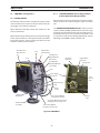
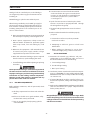
3.1 LOCATION (Figure 3.1)
Proper installation permits free air movement into and out
of the unit and minimizes exposure to dust, dirt, moisture,
and corrosive vapors. A minimum of 18 inches (46 cm)
unrestricted space must be maintained between the rear
panel and the nearest obstruction.
32.25"
19.50"
40.00"
CAUTION: Do not place any ltering device over the
air intake passages of the unit. This would
restrict air intake and cause an overheating
condition and possible failure. Warranty is
void if any type of ltering device is used.
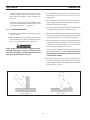
If a forklift vehicle is used for lifting the unit, be sure that
the lift forks are long enough to extend completely under
the base.
Do not operate the machine without the running gear
installed.
3.2 ELECTRICAL INPUT CONNECTIONS
A line disconnect switch must be installed in the input circuit
to the welding machine. This is to provide a safe means to
completely remove all electrical power from the welding
machine whenever it is necessary to perform service on the
unit. (See Figure 3.2A.)
SECTION 3 INSTALLATION
Figure 3.1 Dimensions
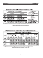
Recommended
Full Primary
Primary Load Input Ground
Input Line Fuse Conductor Conductor
Volts Amperes Size Size Size
208 66 90 6 8
230 61 80 8 8
380 37 50 10 10
380 (50Hz) 38 50 10 10
400 36 50 10 10
400 (50Hz) 36 50 10 10
460 30 40 12 12
575 25 35 12 12
TABLE 3.1 Input Conductor and Fuse Size
OPTIONAL
DIGITAL METER
MODULE
OPTIONAL
BURN BACK
MODULE

22
Figure 3.2A illustrates wiring to a single phase system and
Figure 3.2B illustrates wiring to a three phase system.
The 208/230/380/400/460/575 primary input voltage unit is
provided with a three conductor primary input cable without
plugcap. The ground lead of this cable must be connected
to a reliable ground and the two remaining wires must be
connected to the separately fused lines of the disconnect
or breaker as shown in Figures 3.2C and 3.2D.
3.2.3 PRIMARY VOLTAGE INPUT CONNECTION
All units leave the factory with the primary electrical input
connected for their highest voltage connection (e.g.: 230-
volt for the 208/230-volt units; and 575-volt for the "multi-
voltage" units).
Only qualied personnel may make these changes. Make
certain the primary power has been disconnected and all
safety procedures have been followed before proceeding
with these instructions.
SECTION 3 INSTALLATION
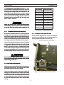
3.2.4a CONNECTING FOR 208 VAC INPUT
Fig. 3.3A shows the 230v and 208v connections for the
208/230 dual voltage model. Change over is made by remov-
ing the right side panel below the wire feed compartment
and switching the primary transformer tap at the top of the
power switch with the unused alternate voltage tap located
next to the main transformer (see Fig. 3.3B).
Both voltage taps (the one currently connected to the
switch and the unused alternate voltage) are marked with
the input voltage requirement. All units are supplied from
the factory connected for the highest voltage (230 vac).
Before switching the voltage taps, verify the actual voltage
requirement as well as the current voltage connection to
be certain re-connection is necessary. If voltage tap re-
connection is necessary, the following paragraphs cover
the procedure to switch the voltage tap for either 208vac
or 230vac input.
Figure 3.3A - Primary Reconnections at
Switch For 208/230 Volt Models
Fig. 3.3B - Position of Alternate Voltage Tap

23
switch (Fig. 3.3C.) to expose the terminals and disconnect
the 208 Vac lead from the top of the switch as shown in Fig.
3.3A. Insulate the 208 Vac lead that was removed from the
power switch with sleeving or approved electrical tape
and re-position to a safe area beside the transformer (see
Fig. 3.3B), leaving a minimum of one inch clearance from
other components and the side panel.
Connect the proper voltage (208 Vac or 230 Vac) tap to the
power switch and tighten securely. Check all other leads
connected to the power switch for tightness and clearance
from internal components before securing the insulating
cover around the power switch. Replace the side panel.
When changing the input voltage connections, the
unused lead must be insulated and positioned to pre-
vent contact with any other internal components of
the machine or the machine side panel. The clearance
between the unused lead and other components must
be at least one inch (see Fig. 3.3B for illustration of the
proper position). FAILURE TO INSULATE AND POSITION
THIS LEAD PROPERLY WILL CAUSE A SERIOUS SHOCK
HAZARD.
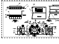
3.2.5 RECONNECTING FROM 575 VAC INPUT
Figure 3.4 & Table 3.2 shows how to reconnect the "multi-
voltage" model from a 575-volt input to each of the available
voltage inputs. These connections are made by removing
the right side panel below the wire feeding compartment,
and locating the primary voltage changeover terminal
board in the center of the lower compartment. This board
contains copper links which must be reconnected to match
the silk-screened voltage designations for the input you
plan to use (it comes factory-connected for a 575-volt
input), see Figure 3.4.
The terminal labeled GRD is connected to the welding
machine chassis and is for ground purposes only. It
must be connected to a good electrical ground. Do not
connect a conductor from the terminal labeled GRD to
any one of the L1, L2 terminals as this will result in an
electrically hot welding machine chassis.
After the panel is removed, locate the 208 Vac lead (Fig. 3.3B)
and cut the tie-wrap to remove the insulation sleeving (on
early models this lead may have been wrapped with black
electrical tape). Open the insulating cover around the power
switch (Fig. 3.3C.) to expose the terminals and disconnect
the 230 Vac lead from the top of the switch as shown in Fig.
3.3A. Insulate the 230 Vac lead that was removed from the
power switch with sleeving or approved electrical tape
and re-position to a safe area beside the transformer (see
Fig. 3.3B), leaving a minimum of one inch clearance from
other components and the side panel.
3.2.4b CONNECTING FOR 230 VAC INPUT
After the panel is removed, locate the 230 Vac lead (Fig. 3.3B)
and cut the tie-wrap to remove the insulation sleeving (on
early models this lead may have been wrapped with black
electrical tape). Open the insulating cover around the power
SECTION 3 INSTALLATION
Fig. 3.3C - Power Switch Connection
Figure 3.3.1-Primary Reconnections at Voltage Change-
over Terminal Board for
208/230/380/400/460/575Volt Models

24
SECTION 3 INSTALLATION
PRIMARY VOLTAGE CONNECTION CHART
VOLTAGE CONNECTION NO. OF STRIPS
208
1 - 2 1
6 - 7 1
7 - 8 FLEX
230
1 - 2 1
6 - 7 1
5 - 8 FLEX
380
3 - 7 2
4 - 8 FLEX
400
2 - 6 2
7 - 8 FLEX
460
2 - 6 2
4 - 8 FLEX
575
2 - 3 2
4 - 8 FLEX
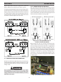
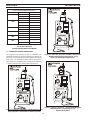
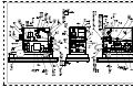
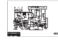
3.3 SECONDARY OUTPUT CONNECTIONS
The Migmaster 275 Welding System is completely self-
contained so that the front panel welding gun ttings are
internally connected to the electrode polarity cable on the
front panel. The electrode polarity cable is inserted into
either the Plus (+) SLOPE tap, Plus (+) FLAT tap, or the Minus
(-) Tap depending on the polarity and slope desired.
Table 3.2 Primary Reconnections at Voltage Change-
over Terminal Board for
208/230/380/400/460/575Volt Models
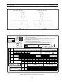
Figure 3.5 Short Arc - Solid Wire - DC Electrode Positive
Steep Slope for a soft smooth arc with low spatter.
Figure 3.6 Short Arc, Spray Arc Solid Wire and Fluxcore
- DC Electrode Positive Steep Slope for a crisp
driving arc with higher output power.
Figure 3.7 Gassless Fluxcore - DC Electrode Negative
Steep Slope for a crisp driving arc with
higher output power.
OPTIONAL
DIGITAL METER
MODULE
OPTIONAL
BURN BACK
MODULE
OPTIONAL
DIGITAL METER
MODULE
OPTIONAL
BURN BACK
MODULE
OPTIONAL
DIGITAL METER
MODULE
OPTIONAL
BURN BACK
MODULE

25
3.4 TORCH CONNECTIONS
The GunMaster 250 supplied standard with the Migmaster
275 System, is provided with a NAS-type connector which
connects directly to the gun receptacle on the front panel.
Line up the NAS pin to the hole, rmly push on and tighten
the locking thumb screw. Connect the trigger lead to the gun
receptacle and to the trigger receptacle on the machine.
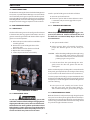
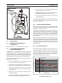
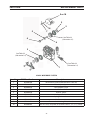
3.5 WIRE FEEDER MECHANISM
3.5.1 DRIVE ROLLS
The drive roll has two grooves: the small groove feeds 0.035
in. diameter wire, the large groove feeds 0.045 in. wire. The
groove nearest the gear motor feeds the wire. If the required
groove is not in that position:
A. Release the pressure drive roll lever and lift the
assembly upward.
B. Remove the screw holding the drive roll to
the motor shaft.
C. Reverse the drive roll on the drive roll shaft.
D. Replace the screw and tighten.
E. Secure the pressure drive roll assembly.
3.5.2 WELDING WIRE SPOOL
As with any work area, make sure safety glasses with
side shields are worn when handling or changing wire or
clipping wire o at the spool or at the end of the torch.
Hold onto the wire coming o the spool with one hand
before clipping. Serious eye injury can result due to the
springiness of the wire which can quickly unravel, or a
cut wire end which may shoot across the room.
Install a spool of welding wire on the hub as follows:
A. Unscrew spool nut from hub.
B. Place wire spool on hub to rotate clockwise as wire
is unwound; hub pin must engage hole in spool.
C. Replace nut.
3.5.3 THREADING WELDING WIRE
When the power switch is on, and gun trigger is de-
pressed, the electrode becomes electrically hot, and
the feed rolls are activated. Keep ngers clear of the
drive mechanism.
A. Turn power switch to "OFF".
B. Release pressure drive roll assembly. Check that
proper wire diameter groove is in the inner posi
tion.
CAUTION: Before threading welding wire through casing,
make sure chisel point and burrs have been
removed from wire end to prevent wire from
jamming in gun casing or liner.
C. Feed the wire from the spool through the inlet
guide, across the drive roll groove and into the
outlet guide.
Make sure that the proper “outlet guide” is inserted into the
front-panel gun adapter for the size and type of wire being
used, see Table 2.2 for wire feed accessories (Section 2.5).
To insure proper wire feeding, it is important that the wire
be kept clean and that the drive rolls be periodically cleaned
of any chips or scale that might be carried into the gun liner
and cause sticking.
D. Lower pressure roll assembly and secure. Check
that the gears mesh. Turn the power switch to
"ON". Feed wire through to gun tip with gun trigger.
3.5.4 BRAKE DRAG ADJUSTMENT
Brake disc friction should provide enough drag to keep the
wire spool or core from spinning freely after wire feed stops.
If adjustment is required, turn adjusting screw clockwise to
increase drag, counterclockwise to decrease it. Drag should
be just low enough to limit wire overrun.
SECTION 3 INSTALLATION
Fig. 3.8 WIRE DRIVE ASSEMBLY

26
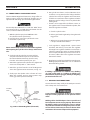
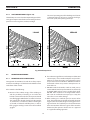
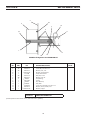
3.6 CONNECTION OF SHIELDING GAS SUPPLY
The R-33-FM-580 Regulator-Flowmeter is designed for use
with an argon or argon-mix cylinder of shielding gas. It is
adjustable for delivering up to 50 cfh through the torch.
Do Not adapt R-33-FM-580 for use with CO
2
. Relief device
may rupture if CO
2
is used with the R-33-FM-580. For CO
2
service, order R-33-FM-320, P/N 21558.
a. With the cylinder cap in place CAREFULLY slide
the cylinder onto the cylinder tray.
b. Using the chain, secure the cylinder to the unit.
c. Unscrew the cylinder cap.
Never stand directly in front of or behind the regulator
when opening the cylinder valve. Always stand to one
side.
d. Crack the cylinder valve for an instant to blow
away dirt or dust which may have accumulated in
the valve outlet. Be sure to keep your face away
from the valve outlet to protect your eyes.
e. Attach the regulator to the cylinder valve, tighten the
union nut securely with a 1-1/8in. wrench.
f. Attach the gas hose from the rear of the Migmaster
275 to the regulator outlet connection (see Fig. 3.9).
g. Slowly open the cylinder valve a fraction of a turn.
When the regulator pressure gauge pointer stops
moving, open the cylinder valve fully.
OUTLET
CONNECTION
CYLINDER
PRESSURE
GAUGE
CYLINDER
VALVE
SECTION 3 INSTALLATION
h. Using a leak test solution, such as P/N 998771 (8 oz.
container) or soapy water, test for leakage about the
cylinder valve stem, the regulator inlet connection,
and the hose connections at the regulator and at the
Migmaster 275 for leakage. Correct any leaks before
starting work.
i. If work is to be stopped for a half-hour or more, or
the regulator is to be removed from the cylinder, shut
down the regulator as follows:
a. Close the cylinder valve.
b. Release gas from the regulator by closing the torch
trigger lever.
c. When pressure gauge drops to zero, the regulator
is de-pressurized and shutdown.
j. Each regulator is equipped with a porous metal
inlet lter, P/N 71Z33, pressed into the regulator
inlet nipple. No. regulator should be connected to a
cylinder or station valve unless it contains this lter.
You can replace the lter if you have reason to do so.
To remove a lter refer to the regulator instruction
literature for details.
k. Regulators in need of repair should be returned to your
Welding Equipment distributor or to an authorized
Remanufacturing Center.
If welding is performed in a conned area, shielding
gas leaks could result in a buildup of shielding gas
concentration, displacing oxygen, thereby endangering
personnel enter the area.
3.7 WELDING CABLE CONNECTIONS
Connect the work clamp solidly to the workpiece or work
table. Clamp onto a bare metal area.
A good electrical connection to the work is essential
to proper welding operation and to prevent electric
shock.
Welding cables should be kept as short as possible and
be of adequate current carrying capacity. Resistance of
the welding cables and connections causes a voltage
drop which is added to the voltage drop of the arc. Ex-
cessive cable resistance may result in a reduction of the
maximum usable current output of the equipment.
Fig. 3.9 R-33-FM-580 Regulator (Illustrated)

27
The proper operation of this equipment is to a large extent
dependent on the use of welding cables and connections
which are in good condition and of adequate size.
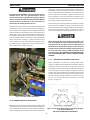
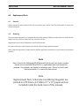
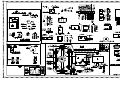
3.8 INSTALLING OPTIONAL BURN BACK MODULE
a. Remove lower blank-cover plate from upper-right front
panel of power supply. Save the mounting hardware.
b. Locate the harness-connected 15-pin plastic plug, P3,
inside the feeder compartment. Note that this plug will
have a jumper plug with jumper wires connected to it
-- remove (and save) the jumper plug. (The jumper plug
must be reinstalled if the module is ever removed.
c. Connect the 15-pin plug into the matching receptacle
on the rear of the optional control module. The plug will
only t one way.
d. Install the control module in place of the blank panel
removed in Step a., using the same four screws that you
saved.
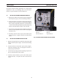
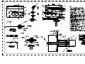
3.9 INSTALLING OPTIONAL DIGITAL METER
a. Remove the top blank-cover plate from the upper right
front panel of the power supply. Save the four mounting
screws.
b. Locate the harness-connected 10-pin plastic plug,PL1,
inside the mounting cavity. This plug does not have a
jumper plug connected to it.
c. Connect the 10-pin plug into the matching receptacle on
the rear of the optional meter module.
d. Install the meter module in place of the blank panel
removed in Step a., using the same four screws that you
saved.
SECTION 3 INSTALLATION
Blank Panel for
Optional
Digital Meter Kit
Blank Panel for
Optional
Burn Back Module
Fig. 3.10 INSTALLING OPTIONAL DIGITAL METER
OPTIONAL
DIGITAL METER
MODULE
OPTIONAL
BURN BACK
MODULE

28
SECTION 3 INSTALLATION
Page is loading ...
Page is loading ...
Page is loading ...
Page is loading ...
Page is loading ...
Page is loading ...
Page is loading ...
Page is loading ...
Page is loading ...
Page is loading ...
Page is loading ...
Page is loading ...
Page is loading ...
Page is loading ...
Page is loading ...
Page is loading ...
Page is loading ...
Page is loading ...
Page is loading ...
Page is loading ...
Page is loading ...
Page is loading ...
Page is loading ...
Page is loading ...
Page is loading ...
Page is loading ...
Page is loading ...
Page is loading ...
Page is loading ...
Page is loading ...
-
 1
1
-
 2
2
-
 3
3
-
 4
4
-
 5
5
-
 6
6
-
 7
7
-
 8
8
-
 9
9
-
 10
10
-
 11
11
-
 12
12
-
 13
13
-
 14
14
-
 15
15
-
 16
16
-
 17
17
-
 18
18
-
 19
19
-
 20
20
-
 21
21
-
 22
22
-
 23
23
-
 24
24
-
 25
25
-
 26
26
-
 27
27
-
 28
28
-
 29
29
-
 30
30
-
 31
31
-
 32
32
-
 33
33
-
 34
34
-
 35
35
-
 36
36
-
 37
37
-
 38
38
-
 39
39
-
 40
40
-
 41
41
-
 42
42
-
 43
43
-
 44
44
-
 45
45
-
 46
46
-
 47
47
-
 48
48
-
 49
49
-
 50
50
-
 51
51
-
 52
52
-
 53
53
-
 54
54
-
 55
55
-
 56
56
-
 57
57
-
 58
58


ESAB Migmaster 275 Welding Package User manual
- Category
- Welding System
- Type
- User manual
Ask a question and I''ll find the answer in the document
Finding information in a document is now easier with AI
Related papers
Other documents
-
Cebora 533 Bravo 170 combi User manual
-
-
-
-
MK 302/303 Owner's manual
-
-
-
Snap-On MIG 110 Operating Instructions Manual
-
-
NOVA of California 2111017 Operating instructions