ESAB ESP-150 User manual

Category
Welding System
Type
User manual
Valid for serial no. 015-xxx-xxxx0558 003 744 110222
ESP-150
Plasma Cutting System
This manual provides installation and operation instructions for the following componenets
beginning with Serial Number 015:
Instruction manual
- 2 -
TOCa
Rights reserved to alter specifications without notice.
1 USER RESPONSIBILITY 3. . . . . . . . . . . . . . . . . . . . . . . . . . . . . . . . . . . . . . . . . . . .
2 SAFETY PRECAUTIONS - English 3. . . . . . . . . . . . . . . . . . . . . . . . . . . . . . . . . . .
3 PRECAUCION DE SEGURIDAD - Spanish 7. . . . . . . . . . . . . . . . . . . . . . . . . . . .
4 MESURES DE SECURITE - French 11. . . . . . . . . . . . . . . . . . . . . . . . . . . . . . . . . .
ESP-150 Plasmarc™ System 15. . . . . . . . . . . . . . . . . . . . . . . . . . . . . . . . . . . . . . . . .
Specifications ESP-150 15. . . . . . . . . . . . . . . . . . . . . . . . . . . . . . . . . . . . . . . . . . . . . .
5 INTRODUCTION 16. . . . . . . . . . . . . . . . . . . . . . . . . . . . . . . . . . . . . . . . . . . . . . . . . . .
5.1 PT-26 16. . . . . . . . . . . . . . . . . . . . . . . . . . . . . . . . . . . . . . . . . . . . . . . . . . . . . . . . . . . . . . . . . . . .
6 INSTALLATION 19. . . . . . . . . . . . . . . . . . . . . . . . . . . . . . . . . . . . . . . . . . . . . . . . . . . .
6.1 General 19. . . . . . . . . . . . . . . . . . . . . . . . . . . . . . . . . . . . . . . . . . . . . . . . . . . . . . . . . . . . . . . . . .
6.2 Inspection and placement 19. . . . . . . . . . . . . . . . . . . . . . . . . . . . . . . . . . . . . . . . . . . . . . . . . . .
6.3 Primary input electrical connections 20. . . . . . . . . . . . . . . . . . . . . . . . . . . . . . . . . . . . . . . . . .
6.4 Torch connections 26. . . . . . . . . . . . . . . . . . . . . . . . . . . . . . . . . . . . . . . . . . . . . . . . . . . . . . . . .
6.5 Gas supply connections 27. . . . . . . . . . . . . . . . . . . . . . . . . . . . . . . . . . . . . . . . . . . . . . . . . . . .
6.6 Work and earth connections 29. . . . . . . . . . . . . . . . . . . . . . . . . . . . . . . . . . . . . . . . . . . . . . . .
6.7 Torch collant preparation 30. . . . . . . . . . . . . . . . . . . . . . . . . . . . . . . . . . . . . . . . . . . . . . . . . . .
7 OPERATION 31. . . . . . . . . . . . . . . . . . . . . . . . . . . . . . . . . . . . . . . . . . . . . . . . . . . . . . .
7.1 Controls and indicators 31. . . . . . . . . . . . . . . . . . . . . . . . . . . . . . . . . . . . . . . . . . . . . . . . . . . . .
7.2 ESP-150 Adjustments 32. . . . . . . . . . . . . . . . . . . . . . . . . . . . . . . . . . . . . . . . . . . . . . . . . . . . . .
7.3 Operation 33. . . . . . . . . . . . . . . . . . . . . . . . . . . . . . . . . . . . . . . . . . . . . . . . . . . . . . . . . . . . . . . .
7.4 Standoff and cut quality 35. . . . . . . . . . . . . . . . . . . . . . . . . . . . . . . . . . . . . . . . . . . . . . . . . . . .
7.5 Dross formation 36. . . . . . . . . . . . . . . . . . . . . . . . . . . . . . . . . . . . . . . . . . . . . . . . . . . . . . . . . . .
7.6 Summary 36. . . . . . . . . . . . . . . . . . . . . . . . . . . . . . . . . . . . . . . . . . . . . . . . . . . . . . . . . . . . . . . . .
7.7 Commun cutting problems 37. . . . . . . . . . . . . . . . . . . . . . . . . . . . . . . . . . . . . . . . . . . . . . . . . .
7.8 Cutting speed conditions 38. . . . . . . . . . . . . . . . . . . . . . . . . . . . . . . . . . . . . . . . . . . . . . . . . . .
7.9 Recommended gas and current 38. . . . . . . . . . . . . . . . . . . . . . . . . . . . . . . . . . . . . . . . . . . . .
7.10 Cutting Parameters for the PT-26 and ESP-150 39. . . . . . . . . . . . . . . . . . . . . . . . . . . . . . .
8 MAINTENANCE 42. . . . . . . . . . . . . . . . . . . . . . . . . . . . . . . . . . . . . . . . . . . . . . . . . . . .
8.1 Inspection and cleaning 42. . . . . . . . . . . . . . . . . . . . . . . . . . . . . . . . . . . . . . . . . . . . . . . . . . . .
8.2 Flow testing 43. . . . . . . . . . . . . . . . . . . . . . . . . . . . . . . . . . . . . . . . . . . . . . . . . . . . . . . . . . . . . . .
8.3 Spark gap adjustment 44. . . . . . . . . . . . . . . . . . . . . . . . . . . . . . . . . . . . . . . . . . . . . . . . . . . . . .
8.4 Testing and replacing brdige assembly components 44. . . . . . . . . . . . . . . . . . . . . . . . . . . .
9 TROUBLESHOOTING 45. . . . . . . . . . . . . . . . . . . . . . . . . . . . . . . . . . . . . . . . . . . . . .
9.1 Troubleshooting guide 46. . . . . . . . . . . . . . . . . . . . . . . . . . . . . . . . . . . . . . . . . . . . . . . . . . . . . .
9.2 Sequence of operation (see fig 22) 48. . . . . . . . . . . . . . . . . . . . . . . . . . . . . . . . . . . . . . . . . . .
9.3 Status light troubleshooting chart 50. . . . . . . . . . . . . . . . . . . . . . . . . . . . . . . . . . . . . . . . . . . .
10 ORDERING AND REPLACEMENT PARTS 52. . . . . . . . . . . . . . . . . . . . . . . . . . . .
10.1 Replacement parts 52. . . . . . . . . . . . . . . . . . . . . . . . . . . . . . . . . . . . . . . . . . . . . . . . . . . . . . . .
10.2 Ordering numbers 52. . . . . . . . . . . . . . . . . . . . . . . . . . . . . . . . . . . . . . . . . . . . . . . . . . . . . . . . .
11 ASSEMBLY INSTRUCTIONS 53. . . . . . . . . . . . . . . . . . . . . . . . . . . . . . . . . . . . . . . .
12 REVISION HISTORY 54. . . . . . . . . . . . . . . . . . . . . . . . . . . . . . . . . . . . . . . . . . . . . . . .
SCHEMATIC DIAGRAM 56. . . . . . . . . . . . . . . . . . . . . . . . . . . . . . . . . . . . . . . . . . . . . . . .
REPLACEMENT PARTS 62. . . . . . . . . . . . . . . . . . . . . . . . . . . . . . . . . . . . . . . . . . . . . . .
- 3 -
US warnings
Be sure this information reaches the operator.
You can get extra copies through your supplier.
These INSTRUCTIONS are for experienced operators. If you are not fully familiar with the
principles of operation and safe practices for arc welding equipment, we urge you to read
our booklet, “Precations and Safe Practices for Arc, Cutting and Gouging, “Form 52-529.
Do NOT permit untrained persons to install, operate, or maintain this equipment. Do NOT
attempt to install or operate this equipment until you have read and fully understand these
instructions. If you do not fully understand these instructions, contact your supplier for
further information. Be sure to read the Safety Precautions before installing or operating
this equipment.
1 USER RESPONSIBILITY
This equipment will perform in conformity with the description thereof contained in this manual and
accompanying labels and/or insert when installed, operated, maintained and repaired in accordance
with the instruction provided. This equipment must be checked periodically. Malfunctioning or poorly
maintained equipment should not be used. Parts that are broken, missing, worn, distorted or
contaminated should be replaced immediately. Should such repair or replacement become necessary,
the manufacturer recommends that a telephone or written request for service advice be made to the
Authorized Distributor from whom it was purchased.
This equipment or any of its parts should not be altered without the prior written approval of the
manufacturer. The user of this equipment shall have the sole responsibility for any malfunction which
results from improper use, faulty maintenance, damage improper repair or alteration by anyone other
than the manufacturer or a service facility designated by the manufacturer.
2 SAFETY PRECAUTIONS - English
WARNING: These Safety Precautions are for your protection. They summarize precautionary
information from the references listed in Additional Safety Information section. Before performing any
installation or operating procedures, be sure to read and follow the safety precautions listed below as
well as all other manuals, material safety data sheets, labels, etc. Failure to observe Safety
Precautions can result in injury or death.
PROTECT YOURSELF AND OTHERS
Some welding, cutting and gouging precesses are noisy and require ear
protection. The arc, like the sun, emits ultraviolet (UV) and other radiation
and can injure skin and eyes. Hot metal can cause burns. Training in the
proper use of the processes and equipment is essential to prevent accidents.
Therefore:
1. Always wear safety glasses with side shields in any work area, even if welding helmets face
shields and goggles are also required.
2. Use a face shield fitted with the correct filter and cover plates to protect your eyes, face, neck
and ears from sparks and rays of the arc when operating or observing operations. Warn
bystanders not to watch the arc and not to expose themselves to the rays of the electric-arc or
hot metal.
3. Wear flameproof gauntlet type gloves, heavy long-sleeve shirt, cuffless trousers, high-topped
shoes and a welding helmet or cap for protection, to protect against arc rays and hot sparks or
hot metal. A flameproof apron may also be desirable as protection against radiated heat and
sparks.
US
- 4 -
US warnings
4. Hot sparks or metal can lodge in rolled up sleeves, trouser cuffs, or pockets. Sleeves and collars
should be kept buttoned and open pockets eliminated from the front of clothing.
5. Protect other personnel from arc rays and hot sparks with a suitable nonflammable partition or
curtains.
6. Use goggles over safety glasses when chipping slag or grinding. Chipped slag may be hot and
can fly far. Bystanders should also wear goggles over safety glasses.
FIRES AND EXPLOSIONS
Heat from flames and arcs can start fires. Hot slag or sparks can also cause
fires and explosions. Therefore:
1. Remove all combustible materials well away from the work area or cover the materials with a
protective nonflammable covering. Combusible materials include wood, clot, sawdust, liquid and
gas fuels, solvents, pants and coatings papper, etc.
2. Hot sparks or hot metal can fall through cracks or crevices in floors or wall openings and cause a
hidden smoldering fire or fires on the floor below. Make certain that such openings are protected
from hot sparks and metal.
3. Do not weld, cut or perform other hot work until the workpiece has been completely cleaned so
that there are no substances on the workpiece which might produce flammable or toxic vapors.
Do not do hot work on closed containers. They may explode.
4. Have fire extinguishing equipment handy for instant use, such as a garden hose, water pail, sand
bucket, or portable fire extinguisher. Be sure you are trained in its use.
5. Do not use equipment beyond its ratings. For example, overloaded welding cable can overheat
and create a fire hazard.
6. After completing operations, inspect the work area to make certain there are no hot sparks or hot
metal which could cause a later fire. Use fire watchers when necessary.
7. For additional information refer to NFPA Standard 51B, “Fire Prevention in Use of Cutting and
Welding Processes”, available from the National Fire Protection Association, Batterymarch Park,
Quincy, MA 02269.
ELECTRICAL SHOCK
Contact with live electrical parts and ground can cause severe injury or
death. DO NOT use AC welding current in damp areas, if movement is
confined, or if there is danger of falling. Therefore:
1. Be sure the power source frame (chassis) is connected to the ground system of the input power.
2. Connect the workpiece to a good electrical ground.
3. Connect the work cable to the workpiece. A poor or missing connection can expose you or others
to a fatal shock.
4. Use well-maintained equipment. Replace worn or damaged cables.
5. Keep everything dry, including clothing, work area, cables, torch/electrode holder and power
source.
6. Make sure that all parts of your bady are insulated from work and from ground.
7. Do not stand directly on metal or the earth while working in tight quarters or a damp area; stand
on dry boards or an insulating platform and wear rubber-soled shoes.
8. Put on dry, hole-free gloves before turning on the power.
9. Turn off the power before removing your gloves.
10. Refer to ANSI/ASC Standard Z49.1 (listed on next page) for specific grounding
recommendations. Do not mistake the work lead for a ground cable.
US
- 5 -
US warnings
ELECTRIC AND MAGNETIC FIELDS
May be dangerous. Electric current flowing through any conductor causes
localized Electric and Magnetic Fields (EMF). Welding and cutting current
creates EMF around welding cables and welding machines.
Therefore:
1. Welders having pacemakers should consult their physician before welding. EMF may interfere
with some pacemakers.
2. Exposure to EMF may have other health effects which are unknown.
3. Welders should use the following procedures to minimize exposure to EMF:
a. Route the electrode and work cables together. Secure them with tape when possible.
b. Never coil the torch or work cable around your body.
c. Do not place your body between the torch and work cables. Route cables on the same side
of your body.
d. Connect the work cable to the workpiece as close as possible to the area being welded.
e. Keep welding power source and cables as far away from your body as possible.
FUMES AND GASES
Fumes and gases, can cause discomfort or harm, particularly in confined
spaces. Do not breathe fumes and gases. Shielding gases can cause
asphyxiation.
Therfore:
1. Always provide adequate ventilation in the work area by natural or mechanical means. Do not
weld, cut or gouge on materials such as galvanized steel, stainless steel, cooper, zinc, lead
beryllium or cadmium unless positive mechanical ventilation is provided. Do not breathe fumes
from these materials.
2. Do not operate near degreasing and spraying operations. The heat or arc can react with
chlorinated hydrocarbon vapors to form phosgene, a highly toxic gas and other irritant gases.
3. If you develop momentary eye, nose or throat irritation while operating, this is an indication that
ventilation is not adequate. Stop work and take necessary steps to improve ventilation in the work
area. Do not continue to operate if physical discomfort persists.
4. Refer to ANSI/ASC Standard Z49.1 (see listing below) for specific ventilation recommendations.
5. WARNING: This product when used for welding or cutting, produces fumes or gases which
contain chemicals known to the State of Californa to cause birth defects and in some cases
cancer (California Health & Safety Code §25249.5 et seq.)
CYLINDER HANDLING
Cylinders, if mishandled, can rupture and violently release gas. Sudden
rupture of cylinder valve or relief device can injure or kill.
Therefore:
1. Use the proper gas for the process and use the proper pressure reducing regulator designed to
operate from the compressed gas cylinder. Do not use adaptors. Maintain hoses and fittings in
good condition. Follow manufacturer's operating instructions for mounting regulator to a
compressed gas cylinder.
2. Always secure cylinders in an upright position by chain or strap to suitable hand trucks,
undercarriages, benches, wall, post or racks. Never secure cylinders to work tables or fixtures
where they may become part of an electrical circuit.
3. When not in use, keep cylinder valves closed. Have valve protection cap in place if regulator is
not connected. Secure and move cylinders by using suitable hand trucks.
4. Locate cylinders away from heat, sparks and flames. Never strike an arc on a cylinder.
5. For additional information, refer to CGA Standard P-1, “Precations for Safe Handling of
Comporessed Gases in Cylinders”, which is available from Compressed Gas Association, 1235
Jefferson Davis Highway, Arlington, VA 22202.
US
- 6 -
US warnings
EQUIPMENT MAINTENANCE
Faulty or improperly maintained equipment can cause injury or death. Therefore:
1. Always have qualified personnel perform the installaion, troubleshooting and maintenance work.
Do not perform any electrical work unless you are qualified to perform such work.
2. Before performing any maintenance work inside a power source, disconnect the power source
from the incoming electrical power.
3. Maintain cables, grounding wire, connections, power cord and power supply in safe working
order. Do not operate any equipment in faulty condition.
4. Do not abuse any equipment or accessories. Keep equipment away from heat sources such as
furnaces, wet conditions such as water puddles, oil or grease, corrosive atmospheres and
inclement weather.
5. Keep all safety devices and cabinet covers in position and in good repair.
6. Use equipment only for its intended purpose. Do not modify it in any manner.
ADDITIONAL SAFETY INFORMATION
For more information on safe practices for electric arc welding and cutting equipment,
ask your supplier for a copy of “Precautions and Safe Practices for Arc Welding,
Cutting and Gouging”, Form 52-529.
The following publications, which are available from the American Welding Society, 550 N.W. LeJuene
Road, Miami, FL 33126, are recommended to you:
1. ANSI/ASC Z49.1 - “Safety in Welding and Cutting”
2. AWS C5.1 . “Recommended Practices for Plasma Arc Welding”
3. AWS C5.2 - “Recommended Practices for Plasma Arc Cutting“
4. AWS C5.3 - “Recommended Practices for Air Carbon, Arc Gouging and Cutting”
5. AWS C5.5 - “Recommended Practices for Gas Tungsten Arc Welding”
6. AWS C5.6 - “Recommended Practices for Gas Metal Arc welding”
7. AWS SP - “Safe practices” - Reprint, Welding Handbook
8. ANSI/AWS F4.1 - “Recommended Safe Practices for Welding and Cutting of Containers That
Have Held Hazardous Substances”
MEANING OF SYMBOLS
As used throughout this manual: Means Attention! Be Alert!
Means immediate hazards which, if not avoided, will result in
immediate, serious personal injury or loss of life.
Means potential hazards which could result in personal injury or loss
of life.
Means hazards which could result in minor personal injury.
US
- 14 -
US warnings
INFORMATIONS COMPLEMENTAIRES RELATIVES A LA SECURITE Pour plus
d'informations relatives aux règles de sécurité pour les travaux de gougeage, de
découpage et de soudage à l'arc électrique, demander au fournisseur une copie du
formulaire 52/529.
L'American Welding Society, 550 N.W. LeJuene Road, Miami, FL 33126 – USA, publie les documents
suivants dont la lecture est également recommandée :
1. ANSI/ASC Z49.1 - ”Safety in Welding and Cutting”
2. AWS C5.1 . ”Recommended Practices for Plasma Arc Welding”
3. AWS C5.2 - ”Recommended Practices for Plasma Arc Cutting”
4. AWS C5.3 - ”Recommended Practices for Air Carbon, Arc Gouging and Cutting”
5. AWS C5.5 - ”Recommended Practices for Gas Tungsten Arc Welding”
6. AWS C5.6 - ”Recommended Practices for Gas Metal Arc welding”
7. AWS SP - ”Safe practices” - Réédition, Manuel de soudage
8. ANSI/AWS F4.1 - ”Recommended Safe Practices for Welding and Cutting of Containers That
Have Held Hazardous Substances”
SYMBOLES
Signification des symboles utilisés dans ce manuel : = Attention ! Rester prudent !
= danger immédiat ; risque de blessures graves ou mortelles.
= danger potentiel ; risque de blessures graves ou mortelles.
= danger ; risque de blessures légères.
US
- 15 -
bp10da1
ESP-150 Plasmarc™ System
This versatile, all encompassed heavy duty water cooled plasma cutting and gouging
system is ideal for manual and mechanized applications.
S Greater productivity - high speed cutting of most
metals from gauge thickness to 2- in. thick plate
S Versatility - 230/460/575 volt three-phase input
S Greater variation - adjustable output - 25 to 150
amps
S Built-In Water Cooler - simplifies maintenance,
less hookup, no wiring issues, no extra hoses.
Water flow is controlled with power supply
S Water cooled Torch PT-26
S Leather sheath wrapped torch - protects torch
leads from abrasion and molten metal
S Cuts with air, nitrogen, argon-hydrogen mixtures
or nitrogenhydrogen mixtures
S Built-In CNC interface provides easy connection
of automation applications
S Torch design provides perfect electrode
centering - provides longer tip life by minimizing
the possibility of double-arcing
S Torch spare parts kit supplied with each outfit -
ample supply of spare parts to minimize
downtime at no additional cost
S Thermal overload switches - prevents damage if
unit overheats due to insufficient air flow
S Line voltage compensation
S Automatic intermittent cutting - additional capability, permits continuous cutting of grates,
expanded metal, heavy screen material, etc.
S Wheels and cylinder rack - all provided standard for portability and greater utilizationat no
additional cost
S Ideal for plasma gouging
S Three year warranty on console
S One Year warranty on torch
Specifications ESP-150
Input Current and Input Voltagle at Rated
Load
112/56/45 amps, 230/460/575 Vac, 60 Hz, 3 Ph
Output rating
90% duty cycle
100% duty cycle
150 amps @ 120 V
140 amps @ 120 V
Open circuit voltage 370 vdc
Operating temperature -10 to +40° C
Transportation temperature -20 to +55° C
Dimensions w = 21.75 in. (552 mm)
h = 31.5 in. (800 mm)
d = 40 in. (1016 mm)
Weight 766 lbs. (348 kg)
Torch: PT-26 - 70°, 90° or In-Line
Instruction Literature 230/460/575 V F15-687
Sales Literature PAC-21062
US
- 16 -
bp10da2
5 INTRODUCTION
The plasma power source ESP-150 and plasma cutting torch PT-26 are a complete
and safe plasma cutting system for cutting and gouging for manual and mechanized
applications.
5.1 PT-26
Plasma Gas
Type of gas N2, Air, AR-H2, N2-H2
Pressure 100 psig (6.9 bar)
Flow 240 cfh (6.8 M3/h)
Purity required O2 - 99.5% min., N2-99.995% min., Air - clean and dry
Recommended liquid cylinder service
regulators
Inert Gas R-76-150-580LC 19977
Recommended cylinder 2-stage
regulators
Argon-Hydrogen R-77-75-350 998341
Nitrogen R-77-75-580 998343
Industrial Air R-77-150-590 998348
Recommended Heavy-Duty Hi-Flow
station or pipeline regulators
Nitrogen R-76-75-034 19155
Starting Gas/Cutting Gas
Type of gas N2, Air (for Ar-H2 Cut Gas Use N2 or Ar-H2)
Pressure 100 psig (6.9 bar )
Flow 200 cfh (5.66M3/h) at 60 psig (4.1 bar)
Purity required N2 - 99% min., Air - clean and dry
Shield Gas
Type of gas N2 or Air
Pressure 100 psig (6.9 bar) maximum
Flow 200 cfh (5.66 M3/h) at 85 psig (5.86 bar)
Purity required Nitrogen - 99% minimum, Air - clean and dry
Assembly instructions PT-26, see on page 53.
US
- 17 -
bp10da3
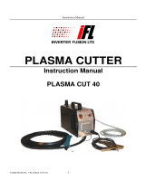
The ESP-150 system is available as pre-engineered basic packages or can be ordered as individual parts
and pieces for a custom system. The basic pre-engineered systems contain the ESP-150 console, plasma
torch, appropriate regulators for the gases indicated, and torch coolant. For torch information, refer to the
PT-26 manual F-15-345.
ESP-150 MANUAL PLASMA CUTTING PACKAGES
AIR PACKAGES Ar/H
2
PACKAGES
0558002909 - ESP-150 / PT-26 25’ 70° / Air
P/N QTY DESCRIPTION
0558002677 1 ESP-150 Console
0558002208 1 PT-26,70°,25’ Plasma torch
0558002864 1 PT-26 Spare Parts Kit, 150A
0558003242 1 Air Reg. Assembly
678724 1 Work Cable, 50'
156F05 4 Coolant (4 gallons)
680794 1 Truck & Cylinder Rack
0558002910 - ESP-150 / PT-26 50’ 70° / Air
P/N QTY DESCRIPTION
0558002677 1 ESP-150 Console
0558002209 1 PT-26,70°,50’ Plasma torch
0558002864 1 PT-26 Spare Parts Kit, 150A
0558003242 3 Air Reg. Assembly
678724 1 Work Cable, 50'
74S76 3 Adaptors
19416 3 Gas Hose
36933GY 1 Reg.Mont
156F05 4 Coolant (4 gallons)
680794 1 Truck & Cylinder Rack
0558002911 - ESP-150 / PT-26 25’ 90° / Air
P/N QTY DESCRIPTION
0558002677 1 ESP-150 Console
35458 1 PT-26,90°,25’ Plasma torch
0558002864 1 PT-26 Spare Parts Kit, 150A
0558003242 3 Air Reg. Assembly
678723 1 Work Cable, 25'
156F05 4 Coolant (4 gallons)
680794 1 Truck & Cylinder Rack
0558002912 - ESP-150 / PT-26 50’ 90° / Air
P/N QTY DESCRIPTION
0558002677 1 ESP-150 Console
35459 1 PT-26,90°,50’ Plasma torch
0558002864 1 PT-26 Spare Parts Kit, 150A
0558003242 3 Air Reg. Assembly
678724 1 Work Cable, 50'
156F05 4 Coolant (4 gallons)
680794 1 Truck & Cylinder Rack
0558002915 - ESP-150 / PT-26 25’ 70° / Ar+H
2
Mix
P/N QTY DESCRIPTION
0558002677 1 ESP-150 Console
0558002208 1 PT-26, 70°, 25’ Plasma torch
0558002864 1 PT-26 Spare Parts Kit, 150A
998341 2 Argon/Hydrogen Mix Regulator
998343 1 Nitrogen Regulator
33122 3 Hoses
678723 1 Work Cable, 25'
19X54 2 Adaptors
156F05 4 Coolant (4 gallons)
680794 1 Truck & Cylinder Rack
0558002916 - ESP-150 / PT-26 50’ 70° / Ar+H
2
Mix
P/N QTY DESCRIPTION
0558002677 1 ESP-150 Console
0558002209 1 PT-26, 70°, 50’ Plasma torch
0558002864 1 PT-26 Spare Parts Kit, 150A
998341 2 Argon/Hydrogen Mix Regulator
998343 1 Nitrogen Regulator
33122 3 Hoses
678724 1 Work Cable, 50'
19X54 2 Adaptors
156F05 4 Coolant (4 gallons)
680794 1 Truck & Cylinder Rack
0558002917 - ESP-150 / PT-26 25’ 90° / Ar+H
2
Mix
P/N QTY DESCRIPTION
0558002677 1 ESP-150 Console
36558 1 PT-26, 90°,25’ Plasma torch
0558002864 1 PT-26 Spare Parts Kit, 150A
998341 2 Argon/Hydrogen Mix Regulator
998343 1 Nitrogen Regulator
33122 3 Hoses
678724 1 Work Cable, 25'
74S76 2 Adaptors
156F05 4 Coolant (4 gallons)
680794 1 Truck & Cylinder Rack
- 18 -
bp10da3
ESP-150 MANUAL PLASMA CUTTING PACKAGES
Ar/H
2
PACKAGES
0558002918 - ESP-150 / PT-26 50’ 90° / Ar+H
2
Mix
P/N QTY DESCRIPTION
0558002677 1 ESP-150 Console
36559 1 PT-26, 90°,50’ Plasma torch
0558002864 1 PT-26 Spare Parts Kit, 150A
998341 2 Argon/Hydrogen Mix Regulator
998343 1 Nitrogen Regulator
33122 3 Hoses
678724 1 Work Cable, 50'
19X54 2 Adaptors
156F05 4 Coolant (4 gallons)
680794 1 Truck & Cylinder Rack
ESP-150 MECHANIZED PLASMA CUTTING PACKAGES
AIR PACKAGES Ar/H
2
PACKAGES
0558002913 - ESP-150 / PT-26 25’ Inline / Air
P/N QTY DESCRIPTION
0558002677 1 ESP-150 Console
0558002320 1 PT-26, 25’ Inline Plasma torch
0558002864 1 PT-26 Spare Parts Kit, 150A
0558003242 3 Air Reg. Assembly
678723 1 Work Cable, 25'
33053 1 Strain Relief
951188 1 Locknut
156F05 4 Coolant (4 gallons)
680794 1 Truck & Cylinder Rack
0558002914 - ESP-150 / PT-26 50’ Inline / Air
P/N QTY DESCRIPTION
0558002677 1 ESP-150 Console
0558002321 1 PT-26, 50’ Inline Plasma torch
0558002864 1 PT-26 Spare Parts Kit, 150A
0558003242 3 Air Reg. Assembly
678724 1 Work Cable, 50'
33053 1 Strain Relief
951188 1 Locknut
156F05 4 Coolant (4 gallons)
680794 1 Truck & Cylinder Rack
0558002919 - ESP-150 / PT-26 25’ Inline / Air
P/N QTY DESCRIPTION
0558002677 1 ESP-150 Console
0558002320 1 PT-26, 25’ Inline Plasma torch
0558002864 1 PT-26 Spare Parts Kit, 150A
998341 2 Argon/Hydrogen Mix Regulator
998343 1 Nitrogen Regulator
33122 3 Hoses
678724 1 Work Cable, 25'
33053 1 Strain Relief
951188 1 Locknut
19X54 2 Adaptors
156F05 4 Coolant (4 gallons)
680794 1 Truck & Cylinder Rack
0558002920 - ESP-150 / PT-26 50’ Inline / Air
P/N QTY DESCRIPTION
0558002677 1 ESP-150 Console
0558002321 1 PT-26, 50’ Inline Plasma torch
0558002864 1 PT-26 Spare Parts Kit, 150A
998341 2 Argon/Hydrogen Mix Regulator
998343 1 Nitrogen Regulator
33122 3 Hoses
678724 1 Work Cable, 50'
33053 1 Strain Relief
951188 1 Locknut
19X54 2 Adaptors
156F05 4 Coolant (4 gallons)
680794 1 Truck & Cylinder Rack
- 19 -
bp10da4
6 INSTALLATION
The installation must be done by a professional.
6.1 General
PRECAUTIONARY MEASURES SHOULD BE TAKEN TO PROVIDE
MAXIMUM PROTECTION AGAINST ELECTRIC SHOCK. BE SURE
THAT ALL POWER IS OFF BY OPENING THE LINE (WALL)
DISCONNECT SWITCH AND UNPLUGG THE POWER CORD TO THE UNIT WHEN PRIMARY
ELECTRICAL CONNECTIONS ARE MADE INSIDE OF THE POWER SUPPLY.
Proper installation can contribute materially to satisfactory and trouble-free operation
of the cutting outfit. Each step in this section should be studied carefully and followed
as closely as possible.
This product is intended for industrial use. In a domestic environment this product
may cause radio interference. It is the user's responsibility to take adequate
precautions.
6.2 Inspection and placement
ELECTRIC SHOCK CAN KILL!
PRECAUTIONARY MEASURES SHOULD BE TAKEN TO PROVIDE
MAXIMUM PROTECTION AGAINST ELECTRIC SHOCK. BE SURE
THAT ALL POWER IS OFF BY OPENING THE LINE (WALL) DISCONNECT SWITCH AND BY
UNPLUGGING THE POWER CORD TO THE UNIT WHEN CONNECTIONS ARE MADE INSIDE
OF THE POWER SOURCE.
PRECAUTIONARY MEASURES SHOULD BE TAKEN TO PROVIDE
MAXIMUM PROTECTION AGAINST ELECTRIC SHOCK. BE SURE
THAT ALL POWER IS OFF BY OPENING THE LINE (WALL)
DISCONNECT SWITCH AND UNPLUGG THE POWER CORD TO THE
UNIT USE LOCK OUT SAFETY PROCEDURES WHEN MAKING
PRIMARY ELECTRICAL CONNECTIONS TO THE POWER SUPPLY.
1. Having removed the shipping container, and before removing the skid, inspect
for evidence of concealed damage which may not have been apparent upon
receipt of the unit. Notify the carrier of any defects or damage at once.
US
- 20 -
bp10da4
2. Check the container for any loose parts. Check air passages on rear panel of
cabinet for any packing materials that may obstruct air flow through the power
supply.
The ESP-150 Power Source is equipped with one lifting eye that enables
hoisting the unit. Be sure the lifting device has adequate capacity to lift the unit
safely. Refer to the SPECIFICATIONS for the unit weight.
3. Mount the components of the TR-21 truck kit to the unit as covered by Form
F-14-413 packed with the truck kit.
4. The machine components are maintained at proper operating temperatures by
forced air which is drawn through the front panel louvers and holes in the base
and out the rear panel by a heavy-duty fan. Locate this machine in an open area
where air can circulate freely through the openings. Leave at least two feet of
clearance between the unit and wall or other obstruction. The area around the
unit should be relatively free of dust, fumes and excessive heat.
(Installing or placing any type of filtering device will restrict the volume of intake
air, thereby subjecting the power source internal components to overheating.
Use of any type of filter device voids the warranty.)
5. A source of clean, dry air that supplies a minimum of 250cfh (7.08 M3H at 110psig)
is required for the cutting operation. The air supply should not exceed 150psig
(10.3 bars) - maximum inlet pressure rating of the filter regulator supplied with the
package.
6.3 Primary input electrical connections
IT IS OF THE UTMOST IMPORTANCE THAT THE CHASSIS BE
CONNECTED TO AN APPROVED ELECTRICAL GROUND TO
PREVENT ACCIDENTAL SHOCKING. TAKE CARE NOT TO CONNECT
THE GROUND WIRE TO ANY OF THE PRIMARY LEADS.
1. A line (wall) disconnect switch, with fuse or circuit breakers, should be provided
at the main power panel. See Fig. 3. The primary power leads should be
insulated copper conductors, and include three power leads and one ground
wire. The wires may be heavy rubber covered cable, or may be run in a solid or
flexible conduit. Refer to Table 1 for recommended input conductors and line
fuse sizes.
US
- 21 -
bp10da4
Fig 3 Typical installation - User supplied 3 Phase fused power disconnect box with recepticle and plug.
Recommended fuse sizes and minimum cable area
Input requirements Input & gnd.
conductor
CU/AWG
Fuse ratings /
Phase, Apms
Volts Phase Amps
220 3 121 No. 1 150
230 3 116 No. 1 150
380 3 70 No. 4 100
415 3 64 No. 6 90
460 3 58 No. 6 80
575 3 45 No. 6 70
Table 1. Sizes per “National Electrical Code” for 75° rated conductors at 30° C ambient. Not more
than three conductors in raceway or cable. Local codes should be followed if they specify sizes other
than those listed above.
ELECTRIC SHOCK CAN KILL!
PRECAUTIONARY MEASURES SHOULD BE TAKEN TO PROVIDE
MAXIMUM PROTECTION AGAINST ELECTRIC SHOCK. BE SURE
THAT ALL POWER IS OFF BY OPENING THE LINE (WALL) DISCONNECT SWITCH AND BY
UNPLUGGING THE POWER CORD TO THE UNIT WHEN CONNECTIONS ARE MADE INSIDE
OF THE POWER SOURCE.
US
- 22 -
bp10da4
2. 60 Hz Models - As shipped from the factory, the ESP-150 is configured for the
highest connectable voltage. If using other input voltages, the links on the
terminal board (TB) inside the unit must be repositioned for the appropriate input
voltage. See figures 4a, 4b and 4c for input voltage configurations. To gain
access to the terminal board, open the access panel on the left side.
Fig 4a
Input Terminal Board
230/460/575 Vac Models.
230 Vac configuration
Fig 4b
Input Terminal Board
230/460/575 Vac Models.
460 Vac configuration
Fig 4c
Input Terminal Board
230/460/575 Vac Models
575 Vac configuration (factory
supplied)
BEFORE MAKING ANY CONNECTIONS TO THE POWER SOURCE
OUTPUT TERMINALS, MAKE SURE THAT ALL PRIMARY INPUT
POWER TO THE MACHINE IS DE-ENERGIZED (OFF) AT THE
DISCONNECT SWITCH.
A POOR CONNECTION OR FAILURE TO CONNECT WORK CABLE
TO WORKPIECE CAN RESULT IN FATAL SHOCK.
FAILURE TO CONNECT THE WORKPIECE TO EARTH GROUND WILL
RESULT IN THE OPENING OF FUSE F3 AND CIRCUIT BREAKER
CB1, DISABLING THE CONSOLE.
US
- 23 -
bp10da4
3. Safety codes specify that the Power Cable GROUND wire be the last to break
connection should the cable be pulled out of the unit. Be sure to cut and strip
wire as shown in Figure 6.
Fig 6 Primary power cable configuration
4. Thread the input conductor cable from the wall disconnect switch through the
strainrelief in the rear panel of the main contactor (MC). Connect the primary
power leads to the main contactor terminals (see Figure 7) using UL listed
pressure wire connectors. Also connect the ground wire to the stud provided on
the chassis base inside the left-rear of the cabinet. Secure the input cable by
tightening the strain relief coupling.
Fig 7 Input Power Cable - Detail View, left side
1 4-conductor inputcable
(customer supplied)
2 Greed / Yellow 3 Ground Stud
5. Recheck all connections to make sure that they are tight, well insulated, and the
proper connection has been made. Then close access panel and reinstall
fasteners.
US
- 24 -
bp10da4
6. Control mode selection for operation with remote plumbing box
The ESP-150 is supplied from the factory with plug P45 connected to the J4
(MAN) receptacle (torch gases and torch connected directly to the ESP-150
power source). If the unit is to be used with a remote plumbing box, move P45 to
the J5 (MECH) receptacle.
Fig 8 Manual vs. Mechanized Operation
Factory supplied for standard operation - P45 to
J4 (MAN)
P45 moved to the J5 (MECH) position to allow
use of remote plumbing box
US
- 25 -
bp10da4
FAULT
SIGNAL
TO CNC
GAS PREFL0W
SIGNAL
FROM CNC
J1 CONNECTOR
ARC ON
SIGNAL
TO CNC
PLASMA START
SIGNAL
FROM CNC
Note: J1 Mating Plug and Clamp
USER SUPPLIED CABLE
14-pin Straight
Connector 636667
Clamp 6271127
EMERGENCY
STOP SIGNAL
FROM CNC
*)
ARC VOLTAGE
SIGNAL
20:1 DIVIDER
* NOTE: If CNC does not have a normally closed emergency stop switch, a jumper must be installed
between TB1-16 and TB1-20.
Fig 9 J1 remote control receptacle pin configuration for CNC connection
US
- 26 -
bp10da4
6.4 Torch connections
1. Open top front cover to gain access to the torch connections. (Fig. 10)
2. Thread the five service lines (gas, power, and switch lead) of the PT-26 torch
through bushing at upper left corner of the front panel and connect them to the
matching fittings on output terminal. Hose connections should be wrench tight.
Make sure plug of the switch lead is firmly locked in place. Then close and
reinstall the hinged cover.
a. only an arc start signal is required, connect the optional Remote Hand
Switch, ESAB part number 2075600, to the Torch Switch Receptacle on the
hook-up panel in the front of the ESP-150 console. Fig. 11.
b. If a PT-26 In-line Torch is being used in a mechanized installation with a
CNC device, see Fig. 9 for Remote Control Receptacle I/O signal pin
configuration and Fig. 8 for Control Mode Selection instructions.
Fig 10 For manual torch applications, pass the service connections through the rubber grommet in
the front of ESP-150 and make connections as shown.
Fig 11 For mechanized applications using a shielded in-line torch, remove the rubber grommet slide
body through sheet metal front of ESP-150 and tighten with
US
- 27 -
bp10da4
Fig 12 Interconnection diagram - frong of ESP-150
1 Shield gas 4 Water OUT (-) (torch)
2 Water IN (+) (pilot arc) 5 Torch switch receptacle
3 Plasma / start gas
6.5 Gas supply connections
1. Connect the gas supplies. The cylinders may be placed and secured on the
cylinder rack of the truck. Before connecting the regulators, be sure to read,
understand, and follow all instructions packed with each regulator.
2. Connect the gas hoses to the regulators and to the proper fittings (Adaptors:
74S76, Air; 19X54, Ar/H2) on the rear panel of the ESP-150. Connections should
be wrench tight including those that are plugged. (Fig. 14)
Fig 13 Air filter regulator connections
US
  • Page 1 1
  • Page 2 2
  • Page 3 3
  • Page 4 4
  • Page 5 5
  • Page 6 6
  • Page 7 7
  • Page 8 8
  • Page 9 9
  • Page 10 10
  • Page 11 11
  • Page 12 12
  • Page 13 13
  • Page 14 14
  • Page 15 15
  • Page 16 16
  • Page 17 17
  • Page 18 18
  • Page 19 19
  • Page 20 20
  • Page 21 21
  • Page 22 22
  • Page 23 23
  • Page 24 24
  • Page 25 25
  • Page 26 26
  • Page 27 27
  • Page 28 28
  • Page 29 29
  • Page 30 30
  • Page 31 31
  • Page 32 32
  • Page 33 33
  • Page 34 34
  • Page 35 35
  • Page 36 36
  • Page 37 37
  • Page 38 38
  • Page 39 39
  • Page 40 40
  • Page 41 41
  • Page 42 42
  • Page 43 43
  • Page 44 44
  • Page 45 45
  • Page 46 46
  • Page 47 47
  • Page 48 48
  • Page 49 49
  • Page 50 50
  • Page 51 51
  • Page 52 52
  • Page 53 53
  • Page 54 54
  • Page 55 55
  • Page 56 56
  • Page 57 57
  • Page 58 58
  • Page 59 59
  • Page 60 60
  • Page 61 61
  • Page 62 62
  • Page 63 63
  • Page 64 64
  • Page 65 65
  • Page 66 66
  • Page 67 67
  • Page 68 68
  • Page 69 69
  • Page 70 70
  • Page 71 71
  • Page 72 72
  • Page 73 73
  • Page 74 74

ESAB ESP-150 User manual

Category
Welding System
Type
User manual

Ask a question and I''ll find the answer in the document

Finding information in a document is now easier with AI