Page is loading ...

V 2
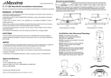
INSTALLATION & OPERATING INSTRUCTIONS
READ & SAVE IMPORTANT SAFETY INSTRUCTIONS
Please read and understand this entire manual before attempting to assemble, operate or install
this product.
1.
This product must be installed in accordance with any applicable installation code(s) by a
qualified electrician or person familiar with the construction and operation of the product and the
hazards involved.
2.
RISK OF FIRE OR ELECTRIC SHOCK : The electrical rating of this product is 120VAC.
3.
WARNING -RISK OF FIRE OR ELECTRIC SHOCK: Install this kit only in lumina
ires
that have the construction features and dimensions shown in this manual.
4.
WARNING - To prevent wiring damage or abrasion, do not expose wiring to edges of sheet
metal or other sharp objects.
5.
Do not make or alter any open holes in an enclosure of wiring or electrical components during
kit installation.
6. THIS DEVICE IS NOT INTENDED FOR USE WITH EMERGENCY EXITS
7. DANGER-RISK OF SHOCK-DISCONNECT POWER BEFORE INSTALLATION
8. WET LOCATION LISTED, ACCEPTABLE IN SHOWER INSTALLATIONS.
9. NOT FOR USE IN SHALLOW HOUSINGS
CAUTION: to avoid possible electrical shock, be sure that power supply is turned off at fuse box
or circuit breaker before installing or servicing fixture. For your safety, read and understand
instructions completely before beginning installation.
• Suitable for Type IC Housings
• Suitable for Type Non-IC Housings
• Suitable for Air Tight Housings.
Replace with LEDR56/830 type Led light.
To order contact FEIT ELECTRIC COMPANY
Tel: 562-463-2852
Http: www.feit.com
Email: [email protected]

install or operate this product.
assemble,
part is missing or damaged, do not attempt topackage contents list and diagram as below. If any
sure all parts are present. Compare parts withBefore beginning installation of this product, make
PACKAGE CONTENTS
V 2
A
B
C
FRONT VIEW
For 6” Recessed
housings
For 5” Recessed
housings
For 6” Recessed
housings
For 5” Recessed
housings
SIDE VIEW
COMPONENTS INCLUDED
MEDIUM BASE ADAPTER
RETROFIT TRIM ASSEMBLY
INSTRUCTION MANUAL
A
B

V 2
Diagram of recessed fixture
6” Recessed housing X=155mm (6¼“)
5” Recessed housing X=135mm (5
⅜”)
(
1. Installation into Existing Recessed Incandescent Fixture:
For use with 6” OR 5" recessed housings (housing sold separately)
LED recessed trim will retrofit into select existing 6” or 5" nominal incandescent housings.
Step 1.
Step 2.
Step 3.
Step 4.
Step 5.
Turn OFF power at switch and fusebox or circuit breaker.
Remove existing trim installed in recessed housing (if necessary).
If applicable, slide lampholder bracket to its upward maximum position. If the lampholder
bracket is less than 4.5 inches from the bottom edge of the fixture enclosure, the lampholder
bracket must be removed.
If necessary, remove the lampholder mounting bracket (see FIG. 2) and the lampholder from the
bracket (see FIG. 2), then attach the provided label to the existing luminaire.
Install adapter into socket (see FIG. 3).
Install the adapter
FIG. 1A FIG. 2
FIG. 3
FIG. 1B
Remove
lamp holder
bracket
(if necessary)
X
(SEE BELOW)

V 2
Step 6.
Step 7.
Step 8.
Step 9.
Connect the orange connectors together (see FIG. 4B).
Insert torsion springs into fixture housing brackets (see FIG. 5).
When installing trim into a 5” recessed housing, the torsion spring must be moved. Unscrew the torsion
spring from the 6” position and move to the 5” position as shown.
Gently push up trim and torsion springs so they begin to expand and lift trim in place (see FIG. 6).
FIG. 4A
FIG. 4B
FIG. 5
FIG. 6
Terminals
Connect the orange connectors
For 6” Recessed
housings
For 5” Recessed
housings

V 2
2. Installation into Existing Recessed LED Fixture with compatible orange connectors
LED recessed trim will retrofit into select existing nominal LED housings.
Step 1.
Step 2.
Step 3.
Step 4.
Step 5.
Step 6.
Turn OFF power at switch and fusebox or circuit breaker.
Remove existing trim installed in recessed housing (if necessary).
Discard medium base adapter
Connect the orange connectors together (see FIG. 2B).
Insert torsion springs into fixture brackets (see FIG. 2A).
Gently push up trim and torsion springs so they begin to expand and lift trim in place (see FIG. 3).
FIG. 1A
Connect the orange connectors
FIG. 2B
FIG. 3
FIG. 2A
Diagram of recessed fixture
(
(
FIG. 1B
4

V 2
PRODUCT ELECTRIC RATING
THE RETROFIT KIT IS ACCEPTED AS A COMPONENT OF A LUMINAIRE WHERE THE SUITABLITITY
OF THE COMBINATION SHALL BE DETERMINED BY CSA OR AUTHORITIES HAVING JURISDICTION.
INPUT
VOLTAGE
/ FREQUENCY
INPUT
CURRENT
INPUT
POWER
120V/60Hz
XXXmA
14 W
WARNING – Risk of fire or electric shock. LED Retrofit Kit installation requires knowledge of luminaires
electrical systems. If not qualified, do not attempt installation. Contact a qualified electrician.
WARNING – Risk of fire or electric shock. Install this kit only in the luminaires that have the construction
features and dimensions shown in the photographs and/or drawings.
Do not make or alter any open holes in an enclosure of wiring or electrical components during kit installation.
WARNING – To prevent wiring damage or abrasion, do not expose wiring to edges of sheet metal or other
sharp objects.
MIN. LAMP COMPARTMENT DIMENSIONS 135mm (5⅜ in) DIA X 190mm (7½ in) HEIGHT When use in
5 inch recessed luminaire
MIN. LAMP COMPARTMENT DIMENSIONS 154mm (6 in) DIA X 188mm (7½ in) HEIGHT When use in 6
inch recessed luminaire
/