Gigabyte 8VT800-RZ User manual
- Category
- Motherboards
- Type
- User manual
This manual is also suitable for

8VT800-RZ /
8VT800-RZ-C
User's Manual
Intel
®
Pentium
®
4 Processor Motherboard
Rev. 1002
12ME-8VT800RZ-1002
Copyright
© 2004 GIGABYTE TECHNOLOGY CO., LTD
Copyright by GIGA-BYTE TECHNOLOGY CO., LTD. ("GBT"). No part of this manual may be reproduced or transmitted in any from
without the expressed, written permission of GBT.
Trademarks
Third-party brands and names are the property of their respective owners.
Notice
Please do not remove any labels on motherboard, this may void the warranty of this motherboard.
Due to rapid change in technology, some of the specifications might be out of date before publication of this booklet.
The author assumes no responsibility for any errors or omissions that may appear in this document nor does the author make a
commitment to update the information contained herein.

Motherboard
8VT800-RZ
May. 07 ,2004
Mother Board
8VT800-RZ
May. 07, 2004

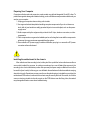
Preparing Your Computer
Computer motherboards and expansion cards contain very delicate Integrated Circuit (IC) chips. To
protect them against damage from static electricity, you should follow some precautions whenever you
work on your computer.
1. Unplug your computer when working on the inside.
2. Use a grounded wrist strap before handling computer components. If you do not have one,
touch both of your hands to a safely grounded object or to a metal object, such as the power
supply case.
3. Hold components by the edges and try not touch the IC chips, leads or connectors, or other
components.
4. Place components on a grounded antistatic pad or on the bag that came with the components
whenever the components are separated from the system.
5. Ensure that the ATX power supply is switched off before you plug in or remove the ATX power
connector on the motherboard.
Installing the motherboard to the chassis
If the motherboard has mounting holes, but they don't line up with the holes on the base and there
are no slots to attach the spacers, do not become alarmed you can still attach the spacers to the
mounting holes. Just cut the bottom portion of the spacers (the spacer may be a little hard to cut off, so
be careful of your hands). In this way you can still attach the motherboard to the base without worrying
about short circuits. Sometimes you may need to use the plastic springs to isolate the screw from the
motherboard PCB surface, because the circuit wire may be near by the hole. Be careful, don't let the
screw contact any printed circuit write or parts on the PCB that are near the fixing hole, otherwise it
may damage the board or cause board malfunctioning.

- 4 -8VT800-RZ/8VT800-RZ-C Motherboard
English
Table of Contents
Chapter 1 Introduction ................................................................................................5
Features Summary...........................................................................................................................5
8VT800-RZ/8VT800-RZ-C Motherboard Layout...............................................................................6
Block Diagram ..................................................................................................................................7
Hardware Installation Process .........................................................................................................8
Step 1: Install the Central Processing Unit (CPU) ..........................................................................8
Step 1-1: CPU Installation ................................................................................................. 9
Step 1-2: CPU Cooling Fan Installation ............................................................................ 9
Step 2: Install Memory Modules ....................................................................................................10
Step 3: Install AGP Card ............................................................................................................... 11
Step 4: Install I/O Peripherals Cables ........................................................................................... 11
Step 4-1: I/O Back Panel Introduction ............................................................................. 11
Step 4-2: Connectors Introduction ...................................................................................12
Chapter 2 BIOS Setup ............................................................................................. 21
The Main Menu (For example: BIOS Ver. : E3) ..........................................................................21
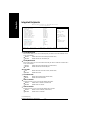
Standard CMOS Features .............................................................................................................23
Advanced BIOS Features .............................................................................................................25
Integrated Peripherals .....................................................................................................................26
Power Management Setup .............................................................................................................28
PnP/PCI Configurations .................................................................................................................30
PC Health Status............................................................................................................................31
Frequency/Voltage Control .............................................................................................................32
Load Fail-Safe Defaults ...................................................................................................................34
Load Optimized Defaults .................................................................................................................34
Set Supervisor/User Password.....................................................................................................35
Save & Exit Setup ......................................................................................................................... 36
Exit Without Saving ........................................................................................................................36
Chapter 3 Install Drivers ........................................................................................... 37

Introduction
English
- 5 -
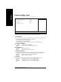
CPU — Socket 478 for Intel
®
Micro FC-PGA2 Pentium
®
4 processor
— Support Intel
®
Pentium
®
4 Processor
(Note1)
with HT Technology
— Support Intel
®
Pentium
®
4 (Northwood) processor
— Intel Pentium
®
4 800
(Note2)
/533/400 MHz FSB
— 2nd cache depends on CPU
Chipset — North Bridge: VIA PT800
— South Bridge: VIA VT8235
Memory — 3 184-pin DDR DIMM sockets
— Supports 128MB/256MB/512MB/1GB unbuffered DRAM
— Supports up to 3GB DRAM (Max)
Slots — 1 AGP slot 8X/4X (1.5V) device support
— 5 PCI slots
On-Board IDE — 2 IDE controller provide IDE HDD/CD-ROM(IDE1, IDE2) with PIO, Bus
Master (Ultra DMA33/ATA66/ATA100/ATA133) operation modes
— Can connect up to 4 IDE devices
On-Board Floppy — 1 Floppy port
On-Board Peripherals — 1 Parallel port
— 2 Serial ports (COMA and COMB)
— 6 USB 2.0/1.1 ports (2 x Rear, 4 x Front by cable)
— 1 Front Audio connector
— 1 PS/2 Keyboard
— 1 PS/2 Mouse
On-Board LAN * — Builit-in VIA VT6103L *
— 1 RJ45 port *
On-Board Sound — VIA VTI617 CODEC
— Support 2/4/6 channel
— Line Out / Line In / Mic In
— SPDIF Out
— CD In / Game connector
BIOS — Licensed AWARD BIOS
— Supports Q-Flash
™
I/O Control — ITE8705F
Hardware M onitor — CPU / System Fan Fail warning
— CPU / System Fan Speed detect
— CPU tem perature detect
— System Voltage Detect
Additional Features — Supports @BIOS
™
— Supports EasyTune
Overclocking — Over Voltage (AGP/DDR) by BIOS
— Over Clock (AGP/DDR/PCI) by BIOS
Form Factor — ATX size form factor, 30.5cm x 21.4cm
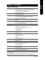
Chapter 1 Introduction
Features Summary
"*" For 8VT800-RZ only.
(Note1): The 8VT800-RZ and 8VT800-RZ-C motherboards support a Prescott processor.
(Note2): The 8VT800-RZ and 8VT800-RZ-C motherboards support Northwood 800MHz processor.

- 6 -8VT800-RZ/8VT800-RZ-C Motherboard
English
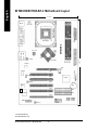
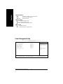
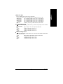
"*" For 8VT800-RZ only.
"#" For 8VT800-RZ-C only.
8VT800-RZ/8VT800-RZ-C Motherboard Layout
8VT800-RZ
KB_MS
COMA
ATX_12V
SOC KET478
CPU_FAN
ATX
FDD
IDE1
IDE2
LPT
DDR2
LINE_IN
LINE_OUT
MIC_IN
USB\
LAN*
Hyper Threading
SPDIF_IO
F_PANEL
PCI5
BIOS
F_U SB2F_U SB1
GAME
F_AU DIO
PWR_LED
CODEC
ITE8705F
BAT
VT8 235
PCI2
PCI3
PCI4
CLR_CMOS
SUR_CEN
PCI1
DDR3
DDR1
CD_IN
SYS_FAN
AGP
VIA PT800
COMB
VT6103L*
-C#
21.4 cm
30.5 cm

Introduction
English
- 7 -
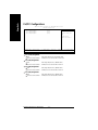
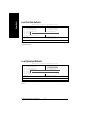
"*" For 8VT800-RZ only.
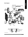
Block Diagram
VT6103L*
RJ45*
Pentium 4
Socket 478
CPU
VIA PT800
AC97
CODEC
VT8235
CPUCLK+/- (100/133/200MHz)
System Bus
400/533/800MHz
266/333/400MHz
GCLKNB
HCLK+/- (100/133MHz)
66MHz
33 MHz
14.318 MHz
48 MHz
48 MHz
33 MHz
LPC BUS
AGP 8X/4X
AGPCLK
(66MHz)
5 PCI
PCICLK
(33MHz)
AC97 Link
MIC
LINE-IN
LINE-OUT
6 USB
(2.0/1.1)
Ports
ATA33/66/
100/133
IDE
Channels
Floppy
LPT Port
PS/2
KB/M ouse
COM
Ports
CLK GEN
GCLKNB
CPUCLK+/- (100/133/200MHz)
AGPCLK (66MHz)
HCLK+/- (100/133/200MHz)
PCICLK (33MHz)
USBCLK (48MHz)
14.318 MHz
33 MHz
ITE8705F
Game Port
BIOS
24 MHz
VCLK (66MHz)
DDR

- 8 -8VT800-RZ/8VT800-RZ-C Motherboard
English
To set up your computer, you must complete the following steps:
Step 1- Install the Central Processing Unit (CPU)
Step 2- Install mem ory modules
Step 3- Install expansion cards
Step 4- Install I/O Peripherals Cables
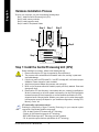
Hardware Installation Process
Step 1: Install the Central Processing Unit (CPU)
Before installing the processor, adhere to the following warning:
1. Please m ake sure the CPU type is supported by the m otherboard.
2. The processor will overheat without the heatsink and/or fan, resulting in perm anent
irreparable damage.
3. If you do not match the CPU socket Pin 1 and CPU cut edge well, it will cause im proper
installation. Please change the insert orientation.
4. Apply thermal grease between the processor and cooling fan.
5. Never run the processor without the heatsink properly and firmly attached. Perm anent
damage will result.
6. Please set the CPU host frequency in accordance with your processor's specifications.
We don't recomm end you to set the system bus frequency over the CPU's specification
because these specific bus frequencies are not the standard specifications for CPU,
chipset and most of the peripherals. Whether your system can run under these specific
bus frequencies properly will depend on your hardware configurations, including CPU,
Memory, Cards… etc.
HT functionality requirement content :
Enabling the functionality of Hyper-Threading Technology for your com puter system
requires all of the following platform components:
- CPU: An Intel
®
Pentium 4 Processor with HT Technology
- Chipset: An VIA Chipset that supports HT Technology
- BIOS: A BIOS that supports HT Technology and has it enabled
- OS: An operation system that has optim izations for HT Technology
Step 2
Step 4
Step 4
Step 4
Step 1
Step 3

- 9 - Hardware Installation Process
English
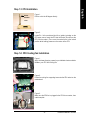
Step 1-1: CPU Installation
Figure 1.
Pull the rod to the 90-degree directly.
Figure 2.
Locate Pin 1 in the socket and look for a (golden) cut edge on the
CPU upper corner. Insert the CPU into the socket. (Do not force the
CPU into the socket.) Then m ove the socket lever to the locked
position while holding pressure on the center of the CPU.
Step 1-2: CPU Cooling Fan Installation
Figure 1.
Apply the therm al tape(or grease) to provide better heat conduction
between your CPU and cooling fan.
Figure 2.
Fasten the cooling fan supporting-base onto the CPU socket on the
motherboard.
Socket
Actuation
Lever
Figure 3.
Make sure the CPU fan is plugged to the CPU fan connector, than
install complete.

- 10 -8VT800-RZ/8VT800-RZ-C Motherboard
English
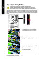
Before installing the m emory modules, adhere to the following warning:
Please note that the DIMM module can only fit in one direction due to the one notch.
Wrong orientation will cause improper installation. Please change the insert orientation.
Step 2: Install Memory Modules
The motherboard has 3 dual inline memory m odule (DIM M) sockets. The BIOS will automatically
detects memory type and size. To install the memory module, just push it vertically into the DIMM
socket. The DIM M module can only fit in one direction due to the notch. M emory size can vary between
sockets.
DDR
Notch
1. The DIMM socket has a notch, so the DIMM
memory module can only fit in one direction.
2. Insert the DIMM mem ory module vertically into
the DIM M socket. Then push it down.
3. Close the plastic clip at both edges of the DIMM
sockets to lock the DIM M m odule.
Reverse the installation steps when you wish to
rem ove the DIM M module.

- 11 - Hardware Installation Process
English
*
PS/2 Keyboard and PS/2 Mouse connector
This connector supports standard PS/2 keyboard and PS/2 m ouse.
Parallel port (LPT)
Device like printer can be connected to Parallel port.
/ Serial port (COMA/ COMB)
Mouse and modem etc. can be connected to Serial port.
LAN port *
LAN is fast Ethernet with 10/100M bps speed.
USB port
Before you connect your device(s) into USB connector(s), please make sure your device(s)
such as USB keyboard, mouse, scanner, zip, speaker...etc. Have a standard USB interface.
Also m ake sure your OS supports USB controller. If your OS does not support USB controller,
please contact OS vendor for possible patch or driver upgrade. For more information please
contact your OS or device(s) vendors.
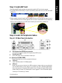
Step 3: Install AGP Card
1. Read the relateAGP card's instruction document before install the AGP card into the computer.
2. If your AGP card has "AGP 4X/8X(1.5V) notch" (show below), please make sure your AGP card is AGP
4X/8X(1.5V).
Step 4: Install I/O Peripherals Cables
Step 4-1: I/O Back Panel Introduction
"*" For 8VT800-RZ only.
AGP 4X/8X notch
3. Please carefully pull out the small white- drawable bar at the end of the AGP slot when you try to
install/ Uninstall the AGP card. Please align the AGP card to the onboard AGP slot and press firm ly
down on the slot .M ake sure your AGP card is locked by the sm all white- drawable bar.

- 12 -8VT800-RZ/8VT800-RZ-C Motherboard
English
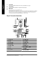
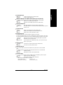
Step 4-2: Connectors Introduction
Line In jack
Devices like CD-ROM , walkm an etc. can be connected to Line In jack.
Line Out jack
Connect the stereo speakers or earphone to this connector.
MIC In jack
Microphone can be connect to MIC In jack.
After installation of the audio driver, you are able to use 2/4/6-channel audio feature by software
selection. You can connect "Front speaker" to "Line Out" jack, Connect "Rear speaker" to
"Line In" jack and connect "Center/Subwoofer" to "MIC In" jack.
5
7
9
1
3
6
10
12
2
4
8
11
141315
16
1) ATX_12V
2) ATX
3) CPU_FAN
4) SYS_FAN
5) IDE1 / IDE2
6) FDD
7) BAT
8) F_PANEL
9) PWR_LED
10) F_AUDIO
11) SUR_CEN
12) CD_IN
13) SPDIF_IO
14) F_USB1/F_USB2
15) GAME
16) CLR_CMOS

- 13 - Hardware Installation Process
English
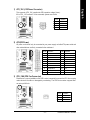
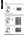
1) ATX_12V (+12V Power Connector)
This connector (ATX_12V) supplies the CPU operation voltage (Vcore).
If this "ATX_12V connector" is not connected, system cannot boot.
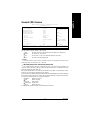
2) ATX (ATX Power)
AC power cord should only be connected to your power supply unit after ATX power cable and
other related devices are firmly connected to the mainboard.
Pin No. Definition
1 3.3V
2 3.3V
3 GND
4 VCC
5 GND
6 VCC
7 GND
8 Power Good
9 5V SB (stand by +5V)
10 +12V
Pin No. Definition
11 3.3V
12 -12V
13 GND
14 PS_ON(soft on/off)
15 GND
16 GND
17 GND
18 -5V
19 VCC
20 VCC
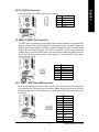
3) CPU_FAN (CPU Fan Connector)
Please note, a proper installation of the CPU cooler is essential to prevent the CPU from running
under abnormal condition or damaged by overheating. The CPU fan connector supports Max.
current up to 600 m A.
Pin No. Definition
1 GND
2 +12V
3 Sense
1
Pin No. Definition
1 GND
2 GND
3 +12V
4 +12V
2 0
1
1 1
1 0
4 3
2 1

- 14 -8VT800-RZ/8VT800-RZ-C Motherboard
English
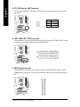
4) SYS_FAN (System FAN Connector)
This connector allows you to link with the cooling fan on the system case to lower the system
temperature.
1
Pin No. Definition
1 GND
2 +12V
3 Sense
5) IDE1 / IDE2 (IDE1 / IDE2 Connector)
Im portant Notice: Please connect first hard disk to IDE1 and connect CD-ROM to IDE2. The red
stripe of the ribbon cable must be the sam e side with the Pin1.
IDE1
IDE2
2
4 0
1
3 9
6) FDD (Floppy Connector)
Please connect the floppy drive ribbon cables to FDD. It supports 360K,720K,1.2M,1.44M and
2.88M bytes floppy disk types. The red stripe of the ribbon cable must be the same side with the
Pin1.
1
3 4
2
3 3

- 15 - Hardware Installation Process
English
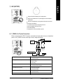
7) BAT (BATTERY)
CAUTION
Danger of explosion if battery is incorrectly replaced.
Replace only with the same or equivalent type recommended by the
manufacturer.
Dispose of used batteries according to the manufacturer's instructions.
If you want to erase CMOS...
1. Turn OFF the computer and unplug the power cord.
2. Remove the battery, wait for 30 second.
3. Re-install the battery.
4. Plug the power cord and turn ON the computer.
+
8) F_PANEL (2 x 10 pins Connector)
Please connect the power LED, PC speaker, reset switch and power switch etc of your chassisfront
panel to the F_PANEL connector according to the pin assignment below.
HD (IDE Hard Disk Active LED) Pin 1: LED anode(+)
Pin 2: LED cathode(-)
SPK (Speaker Connector) Pin 1: VCC(+)
Pin 2- Pin 3: NC
Pin 4: Data(-)
RES (Reset Switch) Open: Normal Operation
Close: Reset Hardware System
PW (Soft Power Connector) Open: Normal Operation
Close: Power On/Off
MSG (Message LED/ Power/ Sleep LED) Pin 1: LED anode(+)
Pin 2: LED cathode(-)
NC NC
1
2
19
20
HD-
HD+
RES+
RES-
NC
IDE Hard Disk Active LED
Reset Switch
SPEAK-
MSG-
MSG+
PW-
PW+
Message LED/
Power/
Sleep LED
Speaker Connector
SPEAK+
Soft Power
Connector

- 16 -8VT800-RZ/8VT800-RZ-C Motherboard
English
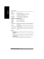
9) PWR_LED
PWR_LED is connect with the system power indicator to indicate whether the system is on/off.
It will blink when the system enters suspend mode. If you use dual color LED, power LED will turn
to another color.
Pin No. Definition
1 MPD+
2 MPD-
3 MPD-
1
Pin No. Definition
1 MIC
2 GND
3 MIC_BIAS
4 Power
5 Front Audio (R)
6 Rear Audio (R)
7 Reserved
8 No Pin
9 Front Audio (L)
10 Rear Audio (L)
10) F_AUDIO (Front Audio Connector)
In order to utilize the front audio header, your chassis must have front audio connector. Also
please make sure the pin assigm ent on the cable is the same as the pin assigm ent on the MB
header. To find out if the chassis you are buying support front audio connector, please contact
your dealer. Please note, you can have the alternative of using front audio connector or of using
rear audio connector to play sound.
11) SUR_CEN (Surround Center Connector)
Please contact your nearest dealer for optional SUR_CEN cable.
Pin No. Definition
1 SUR OUTL
2 SUR OUTR
3 GND
4 No Pin
5 CENTER_OUT
6 BASS_OUT
1
6
2
5
1
1 0 9
2

- 17 - Hardware Installation Process
English
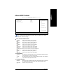
12) CD_IN (CD In Connector)
Connect CD-ROM or DVD-ROM audio out to the connector.
Pin No. Definition
1 CD-L
2 GND
3 GND
4 CD-R
1
13) SPDIF_IO (SPDIF Out Connector)
The SPDIF output is capable of providing digital audio to external speakers or compressed AC3
data to an external Dolby Digital Decoder. Use this feature only when your stereo system has
digital input and output function. Use SPDIF in feature only when your device has digital output
function. Be careful with the polarity of the SPDIF_IO connector. Check the pin assignm ent
carefully while you connect the SPDIF cable, incorrect connection between the cable and connec-
tor will m ake the device unable to work or even damage it. For optional SPDIF cable, please
contact your local dealer.
Pin No. Definition
1 VCC
2 No Pin
3 SPDIF
4 SPDIFI
5 GND
6 GND
1
6
2
5
2 1 0
1 9
Pin No. Definition
1 Power
2 Power
3 USB DX-
4 USB Dy-
5 USB DX+
6 USB Dy+
7 GND
8 GND
9 No Pin
10 NC
14) F_USB1/F_USB2 (Front USB Connector)
Be careful with the polarity of the front USB connector. Check the pin assignment carefully while
you connect the front USB cable, incorrect connection between the cable and connector will m ake
the device unable to work or even damage it. For optional front USB cable, please contact your
local dealer.

- 18 -8VT800-RZ/8VT800-RZ-C Motherboard
English
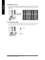
15) GAME (Game Connector)
This connector supports joystick, MIDI keyboard and other relate audio devices. Check the pin
assignment while you connect the gam e cables. Please contact your nearest dealer for optional
game cables.
1
2
1 5
1 6
Pin No. Definition
1 VCC
2 GRX1_R
3 GND
4 GPSA2
5 VCC
6 GPX2_R
7 GPY2_R
8 MSI_R
Pin No. Definition
9 GPSA1
10 GND
11 GPY1_R
12 VCC
13 GPSB1
14 MSO_R
15 GPSB2
16 No Pin
16) CLR_CMOS (Clear CMOS)
You may clear the CMOS data to its default values by this jumper. To clear CMOS, temporarily
short 1-2 pin. Default doesn't include the "Shunter" to prevent from improper use this jumper.
Short: Clear CMOS
1
1
Open: Normal

Introduction
English
- 19 -

- 20 -8VT800-RZ/8VT800-RZ-C Motherboard
English
Page is loading ...
Page is loading ...
Page is loading ...
Page is loading ...
Page is loading ...
Page is loading ...
Page is loading ...
Page is loading ...
Page is loading ...
Page is loading ...
Page is loading ...
Page is loading ...
Page is loading ...
Page is loading ...
Page is loading ...
Page is loading ...
Page is loading ...
Page is loading ...
Page is loading ...
Page is loading ...
-
 1
1
-
 2
2
-
 3
3
-
 4
4
-
 5
5
-
 6
6
-
 7
7
-
 8
8
-
 9
9
-
 10
10
-
 11
11
-
 12
12
-
 13
13
-
 14
14
-
 15
15
-
 16
16
-
 17
17
-
 18
18
-
 19
19
-
 20
20
-
 21
21
-
 22
22
-
 23
23
-
 24
24
-
 25
25
-
 26
26
-
 27
27
-
 28
28
-
 29
29
-
 30
30
-
 31
31
-
 32
32
-
 33
33
-
 34
34
-
 35
35
-
 36
36
-
 37
37
-
 38
38
-
 39
39
-
 40
40


Gigabyte 8VT800-RZ User manual
- Category
- Motherboards
- Type
- User manual
- This manual is also suitable for
Ask a question and I''ll find the answer in the document
Finding information in a document is now easier with AI
Related papers
-
Gigabyte GA-8GEM800 User manual
-
Gigabyte 8I845GE-RZ-C User manual
-
Gigabyte GA-8VT800 User manual
-
Gigabyte 8I845GVM-RZ User manual
-
Gigabyte GA-8VT800-L User manual
-
Gigabyte GA-8I845GV User manual
-
Gigabyte GA-8I865G775-G-RH User manual
-
Gigabyte GA-8S661GXMP-C User manual
-
Gigabyte GA-8IE800 User manual
-