--- 14 ---
Max. cutting dimensions Height x Width mm (inch
)
Right 57˚
(C 12FSA
R/L 57˚ )
(C: R60)
Groove cutting width
Right 45˚
Left 45˚
Bevel
107 x 170 (4-3/16" x 6-11/16")
120 x 130 (4-11/16" x 5-1/8")
[with aux. board 25 mm (1")]
45 x 312 (1-3/4" x 12-1/4")
50 x 260 (1-15/16" x 10-3/16")
[with aux. board
25 mm (1")
]
70 x 312 (2-3/4" x 12-1/4")
75 x 260 (2-15/16" x 10-3/16")
[with aux. board
25 mm (1")
]
Miter left 45˚
(C 12FSA R/L 45˚)
((C) R/L 45˚)
+
Bevel left 45˚
Miter right 31˚
+
Bevel left 45˚
70 x 220 (2-3/4" x 8-5/8")
75 x 180 (2-15/16" x 7-1/16")
[with aux. board 25 mm (1")]
Possible
(with bolt height adjustment)
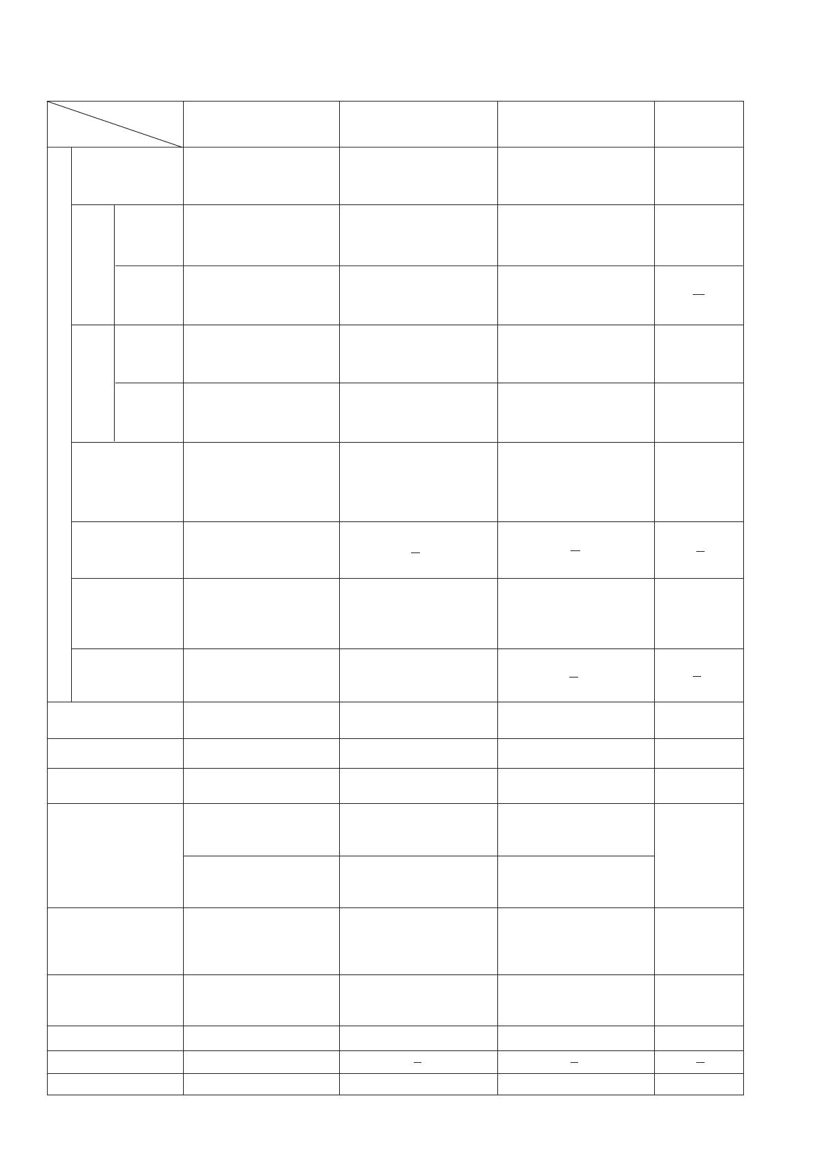
6. COMPARISONS WITH SIMILAR PRODUCTS
Item
Maker
Model
HITACHI
C 12LSH/C 12RSH
0˚ (Right angle)
107 x 312 (4-3/16" x 12-1/4")
120 x 260 (4-11/16" x 10-3/16")
[with aux. board 25 mm (1")]
107 x 220 (4-3/16" x 8-5/8")
120 x 180 (4-11/16" x 7-1/16")
[with aux. board 25 mm (1")]
Miter
Left/right
45˚
Miter cutting ranges
Bevel cutting ranges
Left and right 0˚ --- 45˚
Compound
(miter + bevel)
cutting ranges
Angle stopper positions
Left 0˚ --- 46˚, right 0˚ --- 57˚
Miter left 0˚ --- 45˚/
Miter right 0˚ --- 31˚
Bevel left 0˚ --- 45˚
Miter left 0˚ --- 31˚/
Miter right 0˚ --- 45˚
Bevel right 0˚ --- 45˚
0˚, right and left 15˚, 22.5˚,
31.6˚, 45˚
Miter left 31˚
+
Bevel right 45˚
45 x 265 (1-3/4" x 10-7/16")
50 x 220 (1-15/16" x 8-5/8")
[with aux. board 25 mm (1")]
Saw blade external
diameter mm (inch)
(No. of teeth)
Laser marker
Laser output
305 (12") (60 P)
Provided
70 x 265 (2-3/4" x 10-7/16")
75 x 220 (2-15/16" x 8-5/8")
[with aux. board 25 mm (1")]
Miter right 45˚
((C) R/L 45˚)
+
Bevel right 45˚
45 x 220 (1-3/4" x 8-5/8")
50 x 180 (1-15/16" x 7-1/16")
[with aux. board 25 mm (1")]
<1 mW
Digital display
Provided (C 12LSH only)
107 x 180 (4-3/16" x 7-1/16")
120 x 140 (4-11/16" x 5-1/2")
[with aux. board 25 mm (1")]
40 x 305 (1-9/16" x 12")
45 x 260 (1-3/4" x 10-3/16")
[with aux. board 20 mm (13/16")]
70 x 305 (2-3/4" x 12")
75 x 260 (2-15/16" x 10-3/16")
[with aux. board 20 mm (13/16")]
70 x 220 (2-3/4" x 8-5/8")
75 x 180 (2-15/16" x 7-1/16")
[with aux. board 25 mm (1")]
Possible
(with bolt height adjustment)
HITACHI
C 12FSA
107 x 305 (4-3/16" x 12")
120 x 260 (4-11/16" x 10-3/6")
[with aux. board 20 mm (13/16")]
107 x 220 (4-3/16" x 8-5/8")
120 x 180 (4-11/16" x 7-1/16")
[with aux. board 25 mm (1")]
Left and right 0˚ --- 45˚
Left 0˚ --- 57˚, right 0˚ --- 57˚
0˚, right and left 15˚, 22.5˚,
31.6˚, 35.3˚, 45˚
40 x 265 (1-9/16" x 10-7/16")
45 x 220 (1-3/4" x 8-5/8")
[with aux. board 20 mm (13/16")]
305 (12") (60 P)
Not provided
40 x 220 (1-9/16" x 8-5/8")
45 x 180 (1-3/4" x 7-1/16")
[with aux. board 25 mm (1")]
98 x 155 (3-7/8" x 6-1/8")
120 x 115 (4-11/16" x 4-1/2")
[with aux. board 17 mm (11/16")]
35 x 310 (1-3/8" x 12-1/4")
49 x 230 (1-15/16" x 9")
[with aux. board 34 mm (1-5/16")]
55 x 310 (2-3/16" x 12-1/4")
69 x 230 (2-3/4" x 9")
[with aux. board 34 mm (1-5/16")]
55 x 220 (2-3/16" x 8-5/8")
69 x 162 (2-3/4" x 6-3/8")
[with aux. board 24 mm (15/16")]
Possible
(with bolt height adjustment)
C
98 x 310 (3-7/8" x 12-1/14")
120 x 230 (4-11/16" x 9")
[with aux. board 34 mm (1-5/16")]
98 x 220 (3-7/8" x 8-5/8")
120 x 162 (4-11/16" x 6-3/8")
[with aux. board 24 mm (15/16")]
Left and right 0˚ --- 45˚
Left 0˚ --- 47˚, right 0˚ --- 60˚
Miter left and right 0˚ --- 45˚
Bevel left and right 0˚ --- 45˚
0˚, right and left 15˚, 22.5˚,
30˚, 45˚
305 (12") (70 P)
Not provided
35 x 220 (1-3/8" x 8-5/8")
49 x 162 (1-15/16" x 6-3/8")
[with aux. board 24 mm (15/16")]
Miter right 0˚ --- 60˚/
Bevel left 0˚ --- 35˚
Bevel right 0˚ --- 45˚
102 x 305
(4" x 12")
115 x 299
(4-1/2" x 11-3/4")
102 x 216
(4" x 8-1/2")
115 x 203
(4-1/2" x 8")
57 x 305
(2-1/4" x 12")
79 x 200
(3-1/8" x 7-7/8")
28 x 305
(1-1/8" x 12")
41 x 270
(1-5/8" x 10-5/8")
57 x 216
(2-1/4" x 8-1/2")
79 x 203
(3-1/8" x 8")
28 x 216
(1-1/8" x 8-1/2")
41 x 203
(1-5/8" x 8")
Possible
(with screw height
adjustment)
Left 0˚ --- 50˚,
right 0˚ --- 60˚
Left and right
0˚ --- 48˚
Miter left and right
0˚ --- 45˚
Bevel left and
right 0˚ --- 45˚
0˚, right 15˚, 22.5˚,
31.6˚, 45˚, 60˚
0˚, left 15˚, 22.5˚,
31.6˚, 45˚, 50˚
305 (12") (60 P)
Miter left and right 0˚ --- 45˚
Bevel left 0˚ --- 45˚
Miter left 0˚ --- 31˚/
Miter right 0˚ --- 45˚
Bevel right 0˚ --- 45˚
Not provided
None None
None
P


