Victaulic V01278YBSS Installation guide

Type
Installation guide

This manual is also suitable for

WARNING
• Read and understand all instructions before attempting to install any Victaulic products.
• Depressurize and drain the piping system before attempting to install, remove, or adjust any Victaulic products.
• Wear safety glasses, hardhat, and foot protection during installation.
Failure to follow these instructions could result in serious personal injury and property damage.
RECEIVING THE SHIPMENT
Victaulic Coil Components are a pre-packaged and labeled system
designed to improve efficiency of hooking up HVAC coils. Upon receipt
of the shipment, ensure that the kit is the correct one for the coil being
installed. If any components are damaged or missing, contact Victaulic
at 1-800-PICK VIC.
Union Port Fitting with Air Bleed
The Series 78U Union Port Fitting with Air Bleed can accommodate
up to a three-size reduction using adapters. The connections can be
configured, as listed below:
Female Thread x Male Thread Union
Sweat x Male Thread Union
PermaLynxx Male Thread Union
“Y” Strainer/Ball Valve Combination or “T” Ball Valve
The Series 78Y Strainer/Ball Valve Combination or Series 78T Ball Valve
can accommodate up to a two-size reduction from inlet to outlet. The
connections can be configured, as listed below:
Female Thread x Female Thread
Female Thread x Sweat
Sweat x Sweat
Sweat x Female Thread
PermaLynx x PermaLynx
Balancing Valve
The Series 78K Balancing Valve contains a male threaded union inlet
or female threaded union inlet and can expand up to three sizes to a
female threaded outlet, PermaLynx outlet, or sweat outlet. As an option
to the Series 78K Balancing Valve, a Series 787 Tour and Andersson
Balancing Valve with female threaded ends or a Series 786 Tour and
Andersson Balancing Valve with sweat ends can be incorporated into
the coil hookup.
Coil Hoses
Coil Hoses are available in 1-foot/0.3-meter, 2-foot/0.6-meter, or
3-foot/0.9-meter lengths for hooking up to the inlet and outlet of
the coil. The hoses are available with the following union ends: male
threaded x female threaded swivel or male threaded x male threaded
swivel.
NOTICE
• When the PermaLynx option is chosen (up to 1½-inch/41.3-
mm in size), the Style 604 Male Thread x PermaLynx Adapter
is factory-assembled to the Series 78K Balancing Valve.
Always refer to the I-PermaLynx instructions for complete
installation requirements.
• The maximum pressure rating for PermaLynx products is
200 psi/14 Bar.
OR SUPPLY
Coil Hose
Series 78Y Series 78T
COIL
ATC
OR
RETURN
Series 78UCoil Hose
TA Series 786/787 Series 78K
EXAMPLE COIL COMPONENT ASSEMBLY DRAWING
I-799/79V
INSTALLATION AND MAINTENANCE INSTRUCTIONS
www.victaulic.com
VICTAULIC IS A REGISTERED TRADEMARK OF VICTAULIC COMPANY. © 2010 VICTAULIC COMPANY. ALL RIGHTS RESERVED. PRINTED IN THE USA.
REV_C
Coil Components
SERIES 799 KOIL-KIT
COIL PACK AND SERIES 79V KOIL-KIT
COIL PACK WITH ATC VALVE
IMPORTANT INFORMATION - SWEAT
CONNECTIONS
Sweat connections must be soft soldered with 95/5 (95% tin, 5%
antimony) type solder. When soldering, the valve body must be heat
sinked with a wet cloth or putty at the closest solder connection to
protect internal components, and the flame must be directed away from
the center of the valve body. DO NOT exceed the temperature rating of
the valve (250°F/121°C). Make sure all valves are installed in the correct
direction of flow (refer to flow direction arrow on the valve body). Ball
valves must be in the fully closed position before attempting to solder
the ends. Balancing valves must be in the fully open (4.0) position
before attempting to solder the ends. All valves must be allowed to cool
down to room temperature before attempting operation.
When sweating/soldering near PermaLynx products, use a wet towel to
cover the fitting plus 3 inches/76 mm of the tube closest to the sweat/
solder point. The flame MUST be kept a minimum of 6 inches/152 mm
away from the product. Heat damage to the rubber seals in PermaLynx
products will cause leaks. Refer to the I-PermaLynx installation
instructions for complete information.
IMPORTANT INFORMATION - THREADED
CONNECTIONS
Make sure all threaded connections are clean and free of any burrs.
Apply a small amount of pipe joint compound or Teflon* tape to the
external threads of all threaded pipe connections. DO NOT use a
combination of tape and pipe joint compound. DO NOT get any tape,
pipe joint compound, or other foreign material into the flow path.
IMPORTANT INFORMATION - PERMALYNX
CONNECTIONS
Reference must be made to the I-PermaLynx installation instructions to
ensure proper tube preparation and insertion depth requirements are
achieved. The I-PermaLynx ships with PermaLynx products and can be
downloaded from the www.victaulic.com website.
IMPORTANT INFORMATION - UNION-TYPE
ADAPTERS/CONNECTIONS
The o-rings in union-type adapters/connections must be lubricated
with Victaulic Lubricant or silicone to prevent the o-ring from pinching
or tearing during installation. Tighten union-type adapters/connections
hand-tight, then apply an additional quarter turn. DO NOT over-tighten
the connection.
COIL COMPONENT INSTALLATION
1. Connect the supply side of the Series 78Y Strainer/Ball Valve
Combination or Series 78T Ball Valve to the feed pipe via standard
threading, sweating, or PermaLynx practices. Refer to the prior
sections for important information. Make sure the flow direction
arrow on the valve body is facing the direction of flow and that
the valve body is rotated to the desired position. NOTE: It is not
recommended to have the pressure/temperature ports facing
straight downward.
2. If using Coil Hoses, make the connection to the coil first. Connect
the Coil Hose to the Series 78Y or Series 78T outlet union joint.
Ensure the o-ring is in place on the Series 78Y or Series 78T body.
Apply a thin coat of Victaulic Lubricate or silicone to the o-ring.
Refer to the “Coil Hose Installation” section for details on bend
radius specifications and other installation requirements.
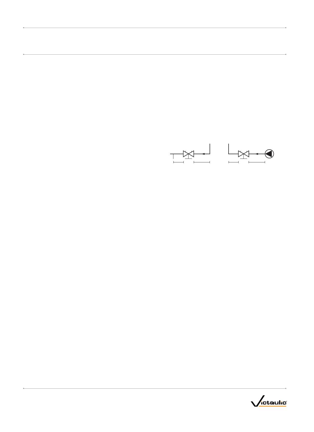
2 D 10 D2 D 5 D
Pump
2D, 5D, or 10D = 2, 5, or 10 pipe diameters
3. Connect the outlet of the balancing valve to the return pipe via
standard threading, sweating, or PermaLynx practices. NOTE:
In order to obtain accurate differential pressure measurements,
turbulence must be minimized. Refer to the drawings above for
examples of piping configurations.
4. Connect the Coil Hose (if applicable) to the inlet of the Series 78U
Union Port Fitting with Air Bleed. NOTE: Between the male union
outlet of the Series 78U and the inlet of the balancing valve, there
is a customer-specified Automatic Temperature Control (ATC)
valve. Ensure the ATC valve contains the correct inlet and outlet
sizes. Cutout lengths, etc. will need to be determined on a case-
by-case basis, depending on the type of ATC valve being installed.
Refer to the instructions supplied with the ATC valve for complete
installation and maintenance requirements.
* Teflon is a registered trademark of the DuPont Company
I-799/79V_2
I-799/79V
INSTALLATION AND MAINTENANCE INSTRUCTIONS
www.victaulic.com
VICTAULIC IS A REGISTERED TRADEMARK OF VICTAULIC COMPANY. © 2010 VICTAULIC COMPANY. ALL RIGHTS RESERVED. PRINTED IN THE USA.
REV_C
Coil Components
SERIES 799 KOIL-KIT
COIL PACK AND SERIES 79V KOIL-KIT
COIL PACK WITH ATC VALVE
Coil Components
SERIES 799 KOIL-KIT
COIL PACK AND SERIES 79V KOIL-KIT
COIL PACK WITH ATC VALVE
COIL HOSE INSTALLATION
CAUTION
• DO NOT introduce chemicals into the system without verifying
compatibility with the Coil Hose materials.
Failure to follow this instruction could cause damage to the
hose, resulting in property damage.
Straight Pipe
NPSM Female
Swivel End
Fiber Gasket
Ferrule
Stainless Steel
Braided Hose
Ferrule
NPT Male
End
Size Inlet Options – inches
Bend
Radius
Maximum Working
Pressure
Nominal ID
inches Male End Thread
NPSM
MNPT Swivel Union inches/mm psi/Bar
½ x ½ NPT ½
2⁄ 375
67 26
¾ x ¾ NPT ¾
300
114 21
1 x 1 NPT 1
300
140 21
1¼ x 1 ¼ NPT 1 ¼
225
172 16
1½ x 1 ½ NPT 1 ½
8⁄ 150
213 10
2 x 2 NPT 2
11¼ 150
286 10
The minimum temperature rating for Coil Hoses is 5°F/15°C.
The maximum temperature rating for Coil Hoses is 230°F/110°C.
Coil Hoses are intended for water applications only. DO NOT attempt to use
these hoses in gas applications.
+4% Minimum
CORRECT
INCORRECT INCORRECT INCORRECT INCORRECT
CORRECT CORRECT
Tight
Coil Hoses can change in length approximately 4% when pressurized.
Allowance must be given to accommodate for this change in length;
therefore, Coil Hoses must not be stretched tightly between the coil and
mating component. Refer to the drawing above for examples of correct
and incorrect bend configurations.
If the bend radius, listed in the table above, falls below the dimension
listed for the applicable hose size, an angle adapter must be used
to avoid sharp bends. NOTE: Exceeding the bend radius can cause
reduction in flow and damage to the hose. If Coil Hoses are stored or
installed at temperatures of 40°F/4°C or lower, the bend radius should
be increased by 50%. Use caution to prevent the hose from collapsing.
The following table contains the minimum distance requirement from
each ferrule to the start of the bend. This table must be referenced to
prevent the hose from being bent too close to the ferrules.
Size
Minimum Distance from Each Ferrule
to Start of Bend
Nominal ID inches inches/mm
½
1
25
¾
1½
38
1
2
51
1¼
64
1½
3
76
2
4
102
To prevent damage to the connections, torque during assembly must
not exceed 30 ft-lbs/41 N•m. The wrench must engage only the hex
portion of the hose ends.
After the system is pressurized, check the Coil Hoses for leaks or
discoloration on the stainless steel braided section or connections. If
leaks are present, replace the affected Coil Hose(s). DO NOT attempt to
repair hoses.
MAINTENANCE
WARNING
• Depressurize and drain the piping system before attempting to
perform any maintenance on Victaulic products.
Failure to follow this instruction could result in serious personal
injury and/or property damage.
20-Mesh Stainless
Steel Strainer Basket
Hose-End Drain
Assembly
Drain Valve
Adapter
Pressure/
Temperature Port
Hex Socket
O-Ring
Union Nut
O-Ring
FLOW
Hex Washer-Head
Screw
Handle
The only maintenance required is for the Series 78Y. A 20-mesh
stainless steel strainer basket is included in the valve body and must
be inspected and cleaned after system startup and a minimum of every
six months thereafter. To access the strainer, remove the drain valve
adapter from the valve body. Clean out the strainer basket and replace it
into the valve body in the same orientation. If any damage to the strainer
basket or o-ring of the drain valve adapter is present, replace them with
new, Victaulic-supplied components.
I-799/79V_3
I-799/79VINSTALLATION AND MAINTENANCE INSTRUCTIONS
www.victaulic.com
VICTAULIC IS A REGISTERED TRADEMARK OF VICTAULIC COMPANY. © 2010 VICTAULIC COMPANY. ALL RIGHTS RESERVED. PRINTED IN THE USA.
REV_C
BALANCING VALVE ASSEMBLY DRAWINGS
Newer Design with Plastic Sleeve (Series 787 Shown Below)
FLOW
Cover
Plastic Sleeve
Valve
Body
Plastic
Handwheel
Bonnet
Assembly
Blue
Holder
Red
Holder
Long Pressure/
Temperature Port
Short Pressure/
Temperature Port
Previous Design with Sleeve and Nut (Series 787 Shown Below)
FLOW
Cover
Nut
Gasket
Gasket
Sleeve
Valve
Body
Plastic
Handwheel
Bonnet
Assembly
Cover
Long Pressure/
Temperature Port
Short Pressure/
Temperature Port
Blue
Holder
Red
Holder
INSTALLING THE BALANCING VALVE DRAIN KIT
The drain kit (part number K-000-786-CBV) for Series 786, 787, and
78K Balancing Valves is sold separately through Victaulic and comes
with two new gaskets, a drainage nipple, and a nut. Contact Victaulic at
1-800-PICK VIC with any order requests or questions regarding this kit.
*NOTE: New gaskets
must be used.
FLOW
Drainage
Nipple
Gasket*
Gasket*
Cover
Nut
1. Remove the components from the long pressure/temperature port,
shown in the assembly drawings above. NOTE: The cover with red
holder will be re-used when the drain kit is installed.
2. Install the drain kit components, as shown in the drawing above.
The new gaskets (provided in the kit) must be installed to prevent
leakage from the port. Re-install the cover with red holder onto the
nut.
3. Locate the recess under the cover. Insert a 5-mm allen key, and
apply 8 - 14 turns to drain from the pressure/temperature port.
PRE-SETTING THE BALANCING VALVE
0
0
1. To pre-set the balancing valve to a certain pressure drop, turn the
plastic handwheel of the bonnet assembly clockwise until the fully
closed (0.0) position is reached, as shown above. For this example
the pre-setting position of 2.3 will be used.
2
3
2. Turn the plastic handwheel of the bonnet assembly
counterclockwise 2.3 turns, as shown above.
2
3
Inner Spindle for
Pre-Setting
3. Using the 3-mm allen key (supplied with the balancing valve), turn
the inner spindle clockwise until it stops. The balancing valve is
now pre-set to the 2.3 position. NOTE: Refer to the graph on this
page, which shows the pressure drop curves for various settings
and flows for each valve size.
BALANCING AND MEASURING
The Series 737 CBI-II Computerized Balancing Instrument or the Series
73M CMI Pressure Differential Meter should be used to obtain direct
readings for temperature, flow, and differential pressures through the
balancing valve. Always refer to the operating manual, provided with the
measuring instrument, for detailed information.
I-799/79V_4
I-799/79V
INSTALLATION AND MAINTENANCE INSTRUCTIONS
www.victaulic.com
VICTAULIC IS A REGISTERED TRADEMARK OF VICTAULIC COMPANY. © 2010 VICTAULIC COMPANY. ALL RIGHTS RESERVED. PRINTED IN THE USA.
REV_C
Coil Components
SERIES 799 KOIL-KIT
COIL PACK AND SERIES 79V KOIL-KIT
COIL PACK WITH ATC VALVE
Coil Components
SERIES 799 KOIL-KIT
COIL PACK AND SERIES 79V KOIL-KIT
COIL PACK WITH ATC VALVE
PRESSURE DROP GRAPH FOR SERIES 786, 787, AND 78K BALANCING VALVES
This graph shows the pressure drop across the pressure test ports of the balancing valve.
A straight line connecting the bars for flow rate, C
V
, and pressure drop shows the relationship between these variables. The position for each valve
size is arrived at by drawing a horizontal line from the C
V
value obtained.
EXAMPLE: To pre-set a 1-inch/33.7-mm valve at a desired flow rate of 6.7 GPM and a pressure drop of 3 feet:
Draw a straight line joining 6.7 GPM and 3 feet. The C
V
= 5.9.
Draw a horizontal line from C
V
5.9. This intersects the bar for a 1-inch/33.7-mm valve at the desired pre-setting of 2.35 turns.
NOTE: If the flow rate falls outside of the scale in the diagram, the reading can be made as follows:
Starting with the example above (3 feet, C
V
5.9, flow rate 6.7 GPM): At 3 feet and a CV of .59, the flow rate = .67 GPM. That is, for a given pressure
drop, it is possible to read 10 times or 0.1 times the flow and C
V
values.
2
1
0.5
0.4
0.3
0.2
0.1
0.05
2.5
40
3.5
3
20
10
5
2
1
0.5
l/s GPM ft.
kPa
Cv Kv
Size
½" ¾" 1½" 2"1" 1¼"½" ¾"
Series 785
Size
Series 786/787
5
4
3
2
1
30
20
10
0.5
1
2
3
4
5
10
30*)
40
50
100
**)
4
3
2.5
0.75
1
0.5
0.4
0.35
0.3
0.25
2
1.5
1
0.5
4
3
2.5
2
1.5
1
0.5
4
3
2.5
2
1.5
1
0.5
4
3
2.5
2
1.5
1
0.5
4
3
2.5
2
1.5
1
0.5
4
3
2
1.5
1
0.5
0.1
0.15
0.2
0.25
0.3
0.4
0.5
0.7
1
1.5
2
2.5
3
4
5
7
10
15
20
25
30
40
50
70
100
Setting, number of turns
0.1
0.15
0.2
0.25
0.3
0.4
0.5
0.7
1
1.5
2
2.5
3
4
5
7
10
15
20
25
30
40
50
70
100
0.75
1
0.5
0.4
0.35
0.3
0.25
2.5
*25 db (A)
**35 db (A)
I-799/79V_5
I-799/79VINSTALLATION AND MAINTENANCE INSTRUCTIONS
www.victaulic.com
VICTAULIC IS A REGISTERED TRADEMARK OF VICTAULIC COMPANY. © 2010 VICTAULIC COMPANY. ALL RIGHTS RESERVED. PRINTED IN THE USA.
REV_C
BONNET ASSEMBLY REPAIR KIT FOR SERIES
786, 787, AND 78K BALANCING VALVES
WARNING
• Depressurize and drain the piping system before attempting
to perform any maintenance or install any kits on Victaulic
products.
Failure to follow this instruction could result in serious personal
injury and/or property damage.
The bonnet assembly repair kit is sold separately through Victaulic.
Contact Victaulic at 1-800-PICK VIC with any order requests or
questions regarding this kit.
The bonnet assembly repair kit consists of a new bonnet assembly
and o-ring for the Series 786, 787, and 78K Balancing Valves in ¾ -
2-inch/26.9 - 60.3-mm sizes. Contact Victaulic for details.
4
0
1. Turn the plastic hand wheel of the bonnet assembly
counterclockwise until the fully open position (4.0) is reached, as
shown above.
2. Remove the bonnet assembly from the balancing valve body.
4
0
3. Turn the plastic handwheel of the replacement bonnet assembly
counterclockwise until the fully open position (4.0) is reached, as
shown above.
4. Apply a very thin layer of Victaulic Lubricant or silicone to the new
o-ring.
4a. Install the new o-ring over the threads of the bonnet assembly, as
shown above. DO NOT use tape or dope on the threads.
5. Tighten the new bonnet assembly into the balancing valve body
until metal-to-metal contact is achieved.
6. To pre-set the balancing valve, refer to the “Pre-Setting the
Balancing Valve” section.
I-799/79V_6
I-799/79V
INSTALLATION AND MAINTENANCE INSTRUCTIONS
www.victaulic.com
VICTAULIC IS A REGISTERED TRADEMARK OF VICTAULIC COMPANY. © 2010 VICTAULIC COMPANY. ALL RIGHTS RESERVED. PRINTED IN THE USA.
REV_C
Coil Components
SERIES 799 KOIL-KIT
COIL PACK AND SERIES 79V KOIL-KIT
COIL PACK WITH ATC VALVE
Coil Components
SERIES 799 KOIL-KIT
COIL PACK AND SERIES 79V KOIL-KIT
COIL PACK WITH ATC VALVE
ADDITIONAL KIT INFORMATION
WARNING
• Depressurize and drain the piping system before attempting
to perform any maintenance or install any kits on Victaulic
products.
Failure to follow this instruction could result in serious personal
injury and/or property damage.
The following kits are sold separately through Victaulic for Coil
Components. Contact Victaulic at 1-800-PICK VIC with any order
requests or questions regarding these kits.
Hose-End Drain Assembly for Series 78Y Strainer/Ball Valve
Combination or Series 78T Ball Valve
(Part Number P-002-78Y-DRN for ¼-inch NPT or
P-004-78Y-DRN for ½-inch NPT)
The hose-end drain assembly is field replaceable for the Series 78Y
or Series 78T. Remove the existing hose-end drain assembly from the
drain valve adapter, and thread the new assembly into the adapter. DO
NOT use tape or dope on the threads.
Replacement Pressure/Temperature Ports for Series 78Y Strainer/
Ball Valve Combination, Series 78T Ball Valve, Series 78U Union Port
Fitting with Air Bleed, or Series 786/787/78K Balancing Valves
(Part Number P-002-78Y-PTP for 78Y/78T/78U or K-000-740-003
for 786/787/78K)
The pressure/temperature ports are field replaceable. Remove the
existing pressure/temperature port(s), and thread the new port(s) into
the valve body. DO NOT use tape or dope on the threads.
Replacement Air Vent for Series 78Y Strainer/Ball Valve Combination
and Series 78U Union Port Fitting with Air Bleed
(Part Number P-002-78U-MAV)
The air vents are field replaceable. Remove the existing air vent, and
thread the new air vent into the valve body. DO NOT use tape or dope
on the threads.
Port Extender for Series 78Y Strainer/Ball Valve Combination,
Series 78T Ball Valve, or Series 78U Union Port Fitting with Air Bleed
(Part Number P-000-78Y-2XT to Clear 2 inches/51-mm of Insulation
or P-000-78Y-4XT to Clear 4 inches/102-mm of Insulation)
In applications where the Coil Components will be insulated, the port
extender is available to extend the pressure/temperature ports of the
Series 78Y or the air vent of the Series 78U to clear 2 inches/
51-mm or 4 inches/102-mm of insulation. Thread the port extender into
the existing pressure/temperature ports or the existing air vent. DO NOT
use tape or dope on the threads.
Handle Extension for Series 78Y Strainer/Ball Valve Combination or
Series 78T Ball Valve (Refer to Table Below for Part Numbers)
Handle Extension
Size
Nominal Diameter
inches/mm
Part Code for 2-inch
Handle Extension
Part Code for 4-inch
Handle Extension
½ - ¾
P-004-78Y-2HL P-004-78Y-4HL
15 - 20
1 - 1 ¼
P-010-78Y-2HL P-010-78Y-4HL
25 - 32
1 ½ - 2
P-020-78Y-2HL P-020-78Y-4HL
40 - 50
In applications where the Coil Components will be insulated, the handle
extension is available to extend the handle of the Series 78Y to clear
2 inches/51-mm of insulation. Remove the hex washer-head screw
from the handle assembly. Remove the handle assembly and install
the handle extension. Re-install the handle assembly onto the handle
extension by using the hex washer-head screw.
I-799/79V_7
I-799/79VINSTALLATION AND MAINTENANCE INSTRUCTIONS
www.victaulic.com
VICTAULIC IS A REGISTERED TRADEMARK OF VICTAULIC COMPANY. © 2010 VICTAULIC COMPANY. ALL RIGHTS RESERVED. PRINTED IN THE USA.
REV_C
I-799/79VINSTALLATION AND MAINTENANCE INSTRUCTIONS
I-799/79V
For complete contact information, visit www.victaulic.com
I-799/79V 2954 REV C UPDATED 06/2010 Z004799001
VICTAULIC IS A REGISTERED TRADEMARK OF VICTAULIC COMPANY. © 2010 VICTAULIC COMPANY. ALL RIGHTS RESERVED. PRINTED IN THE USA.
Coil Components
SERIES 799 KOIL-KIT
COIL PACK AND SERIES 79V KOIL-KIT
COIL PACK WITH ATC VALVE
  • Page 1 1
  • Page 2 2
  • Page 3 3
  • Page 4 4
  • Page 5 5
  • Page 6 6
  • Page 7 7
  • Page 8 8

Victaulic V01278YBSS Installation guide

Type
Installation guide
This manual is also suitable for

Ask a question and I''ll find the answer in the document

Finding information in a document is now easier with AI