Page is loading ...

Evaluation Board User Guide
UG-543
One Technology Way • P. O. Box 9106 • Norwood, MA 02062-9106, U.S.A. • Tel: 781.329.4700 • Fax: 781.461.3113 • www.analog.com
Evaluation Boards for Full-Duplex and Half-Duplex RS-485 Transceivers
in 8-lead/14-lead SOIC Packages
PLEASE SEE THE LAST PAGE FOR AN IMPORTANT
WARNING AND LEGAL TERMS AND CONDITIONS.
Rev. 0 | Page 1 of 16
FEATURES
Easy evaluation of half- and full-duplex RS-485 transceivers
Board layouts for standard RS-485 SOIC footprints
8-lead, SOIC, half-duplex RS-485 (EVAL-RS485HDEBZ)
8-lead, SOIC, full-duplex RS-485 (EVAL-RS485FD8EBZ)
14-lead, SOIC, full-duplex RS-485 (EVAL-RS485FDEBZ)
Power/ground connections through screw terminal blocks
Screw terminal blocks for logic I/O and RS-485 signals
Jumper selectable enable/disable for
RE
and DE
Test points for measuring all signals
Resistors and footprints for termination and biasing
networks
APPLICATIONS
Full- and half-duplex RS-485 transceiver evaluation
EVALUATION KIT CONTENTS
1 EVAL-RS485HDEBZ or
1 EVAL-RS485FD8EBZ or
1 EVAL-RS485FDEBZ
(Main device available separately when ordering)
GENERAL DESCRIPTION
The E VA L-RS485HDEBZ, EVA L -RS485FD8EBZ, and
EVA L-RS485FDEBZ allow quick and easy evaluation of RS-485
transceivers with standard SOIC footprints. The evaluation
board allows all of the input and output functions to be
exercised without the need for external components. Screw
terminal blocks provide convenient connections for power and
ground, digital I/O, and RS-485 signals.
The E VA L-RS485HDEBZ evaluation board has a footprint for
a half-duplex RS-485 transceiver in an 8-lead SOIC package.
The E VA L-RS485FD8EBZ evaluation board has a footprint for
a full-duplex RS-485 transceiver in an 8-lead SOIC package.
The E VA L-RS485FDEBZ evaluation board has a footprint for a
full-duplex RS-485 transceiver in a 14-lead SOIC package.
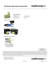
EVAL-RS485HDEBZ
11390-001
Figure 1.
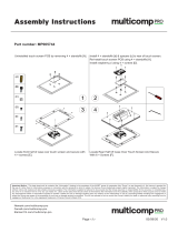
EVAL-RS485FD8EBZ
11390-002
Figure 2.
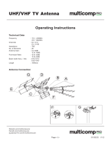
EVAL-RS485FDEBZ
11390-003
Figure 3.

UG-543 Evaluation Board User Guide
Rev. 0 | Page 2 of 16
TABLE OF CONTENTS
Features .............................................................................................. 1
Applications ....................................................................................... 1
Evaluation Kit Contents ................................................................... 1
General Description ......................................................................... 1
EVA L-RS485HDEBZ ....................................................................... 1
EVA L-RS485FD8EBZ ...................................................................... 1
EVA L-RS485FDEBZ......................................................................... 1
Revision History ............................................................................... 2
Evaluation Board Configuration .................................................... 3
Setting Up the Evaluation Board ................................................ 3
Input/Output Connections ......................................................... 3
Other Board Components............................................................4
Evaluation with Applications .......................................................4
Evaluation Board Schematics and Layouts ....................................7
EVA L-RS485HDEBZ ....................................................................7
EVA L-RS485FD8EBZ ...................................................................9
EVA L-RS485FDEBZ .................................................................. 11
Ordering Information .................................................................... 13
EVA L-RS485HDEBZ Bill of Materials .................................... 13
EVA L-RS485FD8EBZ Bill of Materials ................................... 14
EVAL-RS485FDEBZ Bill of Materials ..................................... 15
Related Links ............................................................................... 16
REVISION HISTORY
4/13—Revision 0: Initial Version

Evaluation Board User Guide UG-543
Rev. 0 | Page 3 of 16
EVALUATION BOARD CONFIGURATION
SETTING UP THE EVALUATION BOARD
In order to allow evaluation of any one of over 40 RS-485
transceivers, the evaluation boards are supplied with an
unpopulated footprint for the RS-485 transceiver. The
evaluation board allows all of the input and output functions
to be exercised without the need for additional external
components. Jumper configurations are shown in Table 2.
To use the EVAL -RS485HDEBZ, fit an 8-lead SOIC half-duplex
transceiver to the footprint in the center of the board. For the
EVA L-RS485FD8EBZ, fit an 8-lead SOIC full-duplex trans-
ceiver to the footprint, and for the E VA L -RS485FDEBZ, a
14-lead SOIC full-duplex transceiver. Refer to Table 1 for a list
of parts available for each board.
The board is powered by connecting a 3.3 V or 5 V power
supply (refer to Table 1) to the screw terminals for VCC and
GND at the top of the evaluation board. A 22 µF or 10 µF
decoupling capacitor, C1, is fitted at the connector between
VCC and GND. The VCC pin of the RS-485 transceiver is fitted
with a decoupling capacitor of 100 nF, with a second footprint
for an optional additional capacitor.
Correspondingly labeled test points allow monitoring of the
power supply to the board and probe reference to ground.
INPUT/OUTPUT CONNECTIONS
Digital I/O is connected via a screw terminal block on the left
of the board, allowing wire connections to equipment or a
UART. All boards include connections for data input (DI) and
receiver output (RO). The half-duplex and 14-lead SOIC full-
duplex evaluation boards also have connections for receiver
enable (
RE
) and driver enable (DE). Alternatively, these inputs
can be driven by jumper connections to VCC and GND and/or
connected together (see Table 2).
Connections to an RS-485 bus are made via a screw terminal
block on the right of the board. For the half-duplex board, there
are two bus I/O signals, A and B, for noninverting and inverting
signals, respectively. For full-duplex boards, there are two input
bus signals, A and B, for noninverting and inverting signals,
respectively, and two corresponding output signals, Y and Z.
The bus cable may also include a common ground connection
or shield. These may also be connected to the screw terminal
block on the right of the board.
Test points are available on the board and appropriately labeled
for all digital and bus I/O signals.
Table 1. RS-485 Device and Board Cross Reference
Power Supply
Half-Duplex, 8-Lead
EVAL-RS485HDEBZ
Full-Duplex, 8-Lead
EVAL-RS485FD8EBZ
Full-Duplex, 14-Lead
EVAL-RS485FDEBZ
Enhanced ESD, 3.3 V Supply ADM3072E ADM3071E ADM3070E
ADM3075E ADM3074E ADM3073E
ADM3078E
ADM3077E
ADM3076E
ADM3483E ADM3488E ADM3491E
ADM3485E ADM3490E
ADM3486E
Enhanced ESD, 5 V Supply ADM483E ADM1490E ADM1491E
ADM485E
ADM487E
ADM1487E
Standard, 3.3 V Supply ADM3483 ADM3488 ADM3491
ADM3485 ADM3490
ADM3493
Standard, 5 V Supply ADM1485 ADM488 ADM489
ADM1486 ADM488A ADM489A
ADM4850 ADM4854
ADM4851 ADM4855
ADM4852 ADM4856
ADM4853 ADM4857
ADM483
ADM485

UG-543 Evaluation Board User Guide
Rev. 0 | Page 4 of 16
Table 2. Jumper Configuration
Purpose
Half-Duplex
Board
Full-Duplex
(8-Lead) Board
Full-Duplex
(14-Lead) Board
Connection Description
Select
RE
Input LK1 N/A LK2 A Connects
RE
to VCC (disables receiver output).
B Connects
RE
to GND (enables receiver output).
C Allows
RE
input from screw terminal block.
D Connects
RE
to DE input source.
Select DE Input
LK2
N/A
LK3
A
Connects DE to VCC (enables driver outputs).
B Connects DE to GND (disables driver outputs).
C Allows DE input from screw terminal block.
Connect RT1 LK3 N/A N/A Closed RT1 is connected across A and B.
Open RT1 is disconnected.
Connect RT2 LK4 N/A N/A Closed RT2 is connected across A and B.
Open
RT2 is disconnected.
Connect A to Y N/A LK1 LK5 Closed A is connected to Y.
Open
A is not connected to Y.
Connect B to Z N/A LK2 LK6 Closed B is connected to Z.
Open B is not connected to Z.
OTHER BOARD COMPONENTS
All three boards include footprints for termination resistors
(RT1 and/or RT2) as well as pull-up and pull-down resistors.
Termination resistors of 120 Ω are fitted to the board; these may
be removed or replaced with a different value resistor as needed.
Full-duplex boards can be evaluated with A connected to Y and
B connected to Z (see Table 2). In this configuration, the two
termination resistors are in parallel, so the driver can be
evaluated with a load equivalent to a bus terminated at both ends.
For the half-duplex board, the same effect is achieved by
connecting in two parallel termination resistors using jumpers
on the board. Refer to Table 2 for jumper connections.
Biasing Resistors for Bus-Idle Failsafe
Pull-up and pull-down resistors are not fitted by default, but
may be required to provide an external biasing network for an
idle bus failsafe. These resistors are usually only connected at
one position on the bus and selected to provide a minimum
differential input voltage (V
ID
) between A and B of 200 mV.
Different resistor values are required depending on whether
a 3.3 V or 5 V supply is used, and how much noise margin is
required (that is, V
ID
> 200 mV). ADM3070E to ADM3078E
and ADM4850 to ADM4857 have built-in failsafe for the bus
idle condition. For guidelines, refer to AN-960 Application
Note, RS-485/RS-422 Circuit Implementation Guide.
EVALUATION WITH APPLICATIONS
Full-Duplex RS-485 Transceiver Loopback
For full-duplex transceivers using the EVAL -RS485FDEBZ or
EVA L-RS485FD8EBZ boards, a loopback test can be set up by
closing LK5 and LK6 or LK1 and LK2, respectively. This test
is shown in Figure 4.
A signal generator is connected to DI and this allows
verification of the bus signals and the receiver output. Note
the jumper positions of LK3 (A) and LK2 (B) for the E VA L -
RS485FDEBZ board. In this configuration, the default
termination resistors can be used since both 120 Ω resistors
on the board will be connected in parallel by the loop-back,
ensuring the test is conducted with a standard RS-485 load of
60 Ω (bus terminated at both ends by 120 Ω).
Half-Duplex RS-485 Transceivers Point-to-Point Test
With two boards, a point-to-point test can be set up. Two half-
duplex boards are shown in this configuration in Figure 5.
Note the positions of LK1 and LK2 on each board to enable
the driver on one board and the receiver on the other board.
For EVA L-RS485FDEBZ, these correspond to LK2 and LK3,
although in this case, both boards can have the driver and
receiver enabled if LK5 and LK6 are open and a four-wire
connection is used. For EVA L-RS485FD8EBZ boards, LK1 and
LK2 must be open with a four-wire connection for the point-to-
point link.
LK4 has been removed on each EVA L-RS485HDEBZ board in
order to ensure both ends of the bus have only a 120 Ω load.
For full-duplex boards with a four-wire connection, the correct
termination is on each end of the bus. If EVA L -RS485FDEBZ
boards are used with a two-wire connection and LK5 and LK6
are closed, then one termination resistor needs to be removed
from each board.

Evaluation Board User Guide UG-543
Rev. 0 | Page 5 of 16
Connecting to an Existing RS-485 Network
For a two-wire connection to an existing RS-485 network,
driver enable (DE) should be disabled (LK2 for EVAL -
RS485HDEBZ, LK3 for E VAL -RS485FDEBZ) by moving to
Position B, or else should be controlled externally (Position C)
based on received data.
For a four-wire connection using E VA L-RS485FDEBZ, the
driver can be permanently enabled by placing LK3 in Position A,
if the Y and Z connections are connected only to RS-485
receivers. Otherwise, LK3 should be in Position B or Position C.
For a four-wire connection using E VA L-RS485FD8EBZ, the Y
and Z connections should only be connected to other RS-485
receiver inputs, as shown in Figure 6 for a multinode bus.
These full-duplex parts without driver or receiver enable inputs
can also typically be used in point-to-point four-wire RS-485
bus connections.
OSCILLOSCOPE
A
LK2
LK3
B
C
D
A
B
C
SHIELD
A
RO
RE
DE
DI
B
Z
Y
GND
RO
RE
DE
DI
LK5
LK6
A
B
Z
Y
GND
J1
J3
J2
VCC
EVAL-RS485FDEBZ
3.3V OR 5V
SUPPLY
SIGNAL
GENERATOR
11390-004
Figure 4. Full-Duplex RS-485 Transceiver Loop Back Test
11390-005
OSCILLOSCOPE
A
LK1
LK2
B
C
D
A
B
C
RO
RE
DE
DI
B
A
RO
RE
DE
DI
B
A
GND
J1
J3
VCC
A
LK1
LK2
B
C
D
A
B
C
SHIELD
RO
RE
DE
DI
B
A
GND
SHIELD
GND
RO
RE
DE
DI
LK3
LK4
LK3
LK4
B
A
GND
J1
J5
J5
J3
VCC
EVAL-RS485HDEBZ
EVAL-RS485HDEBZ
3.3V OR 5V
SUPPLY
3.3V OR 5V
SUPPLY
SIGNAL
GENERATOR
Figure 5. Half-Duplex RS-485 Two Board Point-to-Point Test

UG-543 Evaluation Board User Guide
Rev. 0 | Page 6 of 16
SHIELD
A
RO
DI
UART Rx
UART Tx
B
Z
Y
GND
RO
DI
LK1
LK2
RT2
RT1
A
B
Z
Y
GND
J1
J2
VCC
EVAL-RS485FD8EBZ
3.3V OR 5V
SUPPLY
NOTES
1.REMOVE 50Ω TERMINATION RESISTORS FROM EVALUATION BOARD
2.MAXIMUM NUMBER OF NODES: 32.
3.R
T
IS EQUAL TO THE CHARACTERISTIC IMPEDANCE OF THE CABLE USED.
R
T
R
T
R
T
R
T
MASTER NODE
SLAVESLAVE SLAVE
A YZB
NODE N
A YZB
NODE 2
A YZB
NODE 1
MICROCONTROLLER/
PROCESSOR
11390-006
J3
Figure 6. Full-Duplex (8-Lead SOIC) RS-485 Board Connected to Bus and Control Board

Evaluation Board User Guide UG-543
Rev. 0 | Page 7 of 16
EVALUATION BOARD SCHEMATICS AND LAYOUTS
EVAL-RS485HDEBZ
11390-007
Figure 7. EVAL-RS485HDEBZ Schematic

UG-543 Evaluation Board User Guide
Rev. 0 | Page 8 of 16
11390-008
Figure 8. EVAL-RS485HDEBZ Silkscreen
11390-009
Figure 9. EVAL-RS485HDEBZ Component Side
11390-010
Figure 10. EVAL-RS485HDEBZ Solder Side

Evaluation Board User Guide UG-543
Rev. 0 | Page 9 of 16
EVAL-RS485FD8EBZ
11390-011
Figure 11. EVAL-RS485FD8EBZ Schematic

UG-543 Evaluation Board User Guide
Rev. 0 | Page 10 of 16
11390-012
Figure 12. EVAL-RS485FD8EBZ Silkscreen
11390-013
Figure 13. EVAL-RS485FD8EBZ Component Side
11390-014
Figure 14. EVAL-RS485FD8EBZ Solder Side

Evaluation Board User Guide UG-543
Rev. 0 | Page 11 of 16
EVAL-RS485FDEBZ
11390-015
Figure 15. EVAL-RS485FDEBZ Schematic

UG-543 Evaluation Board User Guide
Rev. 0 | Page 12 of 16
11390-016
Figure 16. EVAL-RS485FDEBZ Silkscreen
11390-017
Figure 17. EVAL-RS485FDEBZ Component Side
11390-018
Figure 18. EVAL-RS485FDEBZ Solder Side

Evaluation Board User Guide UG-543
Rev. 0 | Page 13 of 16
ORDERING INFORMATION
EVAL-RS485HDEBZ BILL OF MATERIALS
Table 3.
Quantity Reference Designator Description Supplier/Part Number
1 C1 Capacitor, 100 nF, 0805 Multicomp/MCCA000274
2 C2, C4 Not placed/optional Not applicable
1 C3 Capacitor, 10 µF, Case B Kemet/B45196H3106K209
6 A, B, DE, DI,
RE
, RO Test point, yellow Vero Technologies/20-313140
1 GND Test point, black Vero Technologies/20-2137
1 J1 2-way terminal block Lumberg/KRM 02
2 J3, J5 4-way terminal block Lumberg/KRM 04
1 LK1 8-pin (4 × 2) 0.1" header and shorting block Harwin/M20-9953646 and Harwin/M7566-05
1
LK2
6-pin (3 × 2) 0.1" header and shorting block
Harwin/M20-9953646 and Harwin/M7566-05
2 LK3, LK4 Jumper Block, 2 pin, 0.1" spacing Harwin/M20-9990246 and Harwin/M7566-05
2 R1, R2 Not placed/optional Not applicable
1 R3 Resistor, 0 Ω, 0805 Vishay Draloric/CRCW08050000Z0EA
2
RT1, RT2
Resistor, 120 Ω, 0805
Multicomp/MC 0.1W 0805 1% 120R
1 U1 8-lead SOIC (not placed)
Analog Devices, Inc./see Table 4
1 VCC Test point, red Vero Technologies/20-313137
Table 4. EVAL-RS485HDEBZ Options for U1(Half-Duplex RS-485 Transceivers)
Enhanced ESD, 3.3 V Supply Enhanced ESD, 5 V Supply Standard, 3.3 V Supply Standard, 5 V Supply
ADM3072E ADM3483E ADM483E ADM3483 ADM1485 ADM4850
ADM3075E
ADM3485E
ADM485E
ADM3485
ADM1486
ADM4851
ADM3078E ADM3486E ADM487E ADM3493 ADM483 ADM4852
ADM1487E ADM485 ADM4853
Select the appropriate U1 devices in addition to EVAL -RS485HDEBZ when ordering. Ensure that the device ordered includes an R in the
part number for SOIC devices, for example, ADM3072EARZ.

UG-543 Evaluation Board User Guide
Rev. 0 | Page 14 of 16
EVAL-RS485FD8EBZ BILL OF MATERIALS
Table 5.
Quantity Reference Designator Description Supplier/Part Number
1 C1 Capacitor, 100 nF, 0805 Multicomp/MCCA000274
2 C2, C4 Not placed/optional Not applicable
1 C3 Capacitor, 22 µF, Case C AVX/TAJC226K016RNJ
6 A, B, DI, RO, Y, Z Test point, yellow Vero Technologies/20-313140
1 GND Test point, black Vero Technologies/20-2137
2 J1, J2 2-way terminal block Lumberg/KRM 02
1 J3 6-way terminal block Lumberg/KRM 06
2 LK1, LK2 Jumper Block, 2 pin, 0.1" spacing Harwin/M20-9990246 and Harwin/M7566-05
2 R1, R2 Not placed/optional Not applicable
1 R3 Resistor, 0 Ω, 0805 Vishay Draloric/CRCW08050000Z0EA
2 RT1, RT2 Resistor, 120 Ω, 0805 Multicomp/MC 0.1W 0805 1% 120R
1 U1 8-lead SOIC (not placed)
Analog Devices/see Table 6
1 VCC Test point, red Vero Technologies/20-313137
Table 6. EVAL-RS485FD8EBZ Options for U1(Full-Duplex RS-485 Transceivers, 8-Lead SOIC)
Enhanced ESD, 3.3 V Supply Enhanced ESD, 5 V Supply Standard, 3.3 V Supply Standard, 5 V Supply
ADM3071E ADM3488E ADM1490E ADM3488 ADM4854 ADM4857
ADM3074E ADM3490E ADM3490 ADM4855 ADM488
ADM3077E ADM4856 ADM488A
Select the appropriate U1 devices in addition to EVAL -RS485FD8EBZ when ordering. Ensure that the device ordered includes an R in the
part number for SOIC devices, for example, ADM3071EARZ.

Evaluation Board User Guide UG-543
Rev. 0 | Page 15 of 16
EVAL-RS485FDEBZ BILL OF MATERIALS
Table 7.
Quantity Reference Designator Description Supplier/Part Number
1
C1
Capacitor, 22 µF, Case C
AVX/TAJC226K016RNJ
1 C2 Capacitor, 100 nF, 0805 Multicomp/MCCA000274
2 C3, C4 Not placed/optional Not applicable
6 A, B, DE, DI,
RE
, RO, Y, Z Test point, yellow Vero Technologies/20-313140
1 GND Test point, black Vero Technologies/20-2137
1 J1 2-way terminal block Lumberg/KRM 02
1 J2 4-way terminal block Lumberg/KRM 04
1 J3 6-way terminal block Lumberg/KRM 06
1 LK2 8-pin (4 × 2) 0.1" header and shorting block Harwin/M20-9953646 and Harwin/M7566-05
1 LK3 6-pin (3 × 2) 0.1" header and shorting block Harwin/M20-9953646 and Harwin/M7566-05
2 LK5, LK6 Jumper Block, 2 pin, 0.1" spacing Harwin/M20-9990246 and Harwin/M7566-05
2 R1, R2 Not placed/optional Not applicable
1 R3 Resistor, 0 Ω, 0805 Vishay Draloric/CRCW08050000Z0EA
2 RT1, RT2 Resistor, 120 Ω, 0805 Multicomp/MC 0.1W 0805 1% 120R
1 U1 14-lead SOIC (not placed)
Analog Devices/see Table 8
1 VCC Test point, red Vero Technologies/20-313137
Table 8. EVAL-RS485FDEBZ Options for U1(Full-Duplex RS-485 Transceivers, 14-Lead SOIC)
Enhanced ESD, 3.3 V Supply
Enhanced ESD, 5 V Supply
Standard, 3.3 V Supply
Standard, 5 V Supply
ADM3070E ADM3076E ADM1491E ADM3491 ADM489
ADM3073E
ADM3491E
ADM489A
Select the appropriate U1 devices in addition to EVAL -RS485FDEBZ when ordering. Ensure that the device ordered includes an R in the
part number for SOIC devices, for example, ADM3070EARZ.

UG-543 Evaluation Board User Guide
Rev. 0 | Page 16 of 16
RELATED LINKS
Resource
Description
AN-960 RS-485/RS-422 Circuit Implementation Guide
RS-485/RS-422 Products RS-485/RS-422 Product Selection
ESD Caution
ESD (electrostatic discharge) sensitive device. Charged devices and circuit boards can discharge without detection. Although this product features patented or proprietary protection
circuitry, damage may occur on devices subjected to high energy ESD. Therefore, proper ESD precautions should be taken to avoid performance degradation or loss of functionality.
Legal Terms and Conditions
By using the evaluation board discussed herein (together with any tools, components documentation or support materials, the “Evaluation Board”), you are agreeing to be bound by the terms and conditions
set forth below (“Agreement”) unless you have purchased the Evaluation Board, in which case the Analog Devices Standard Terms and Conditions of Sale shall govern. Do not use the Evaluation Board until you
have read and agreed to the Agreement. Your use of the Evaluation Board shall signify your acceptance of
the Agreement. This Agreement is made by and between you (“Customer”) and Analog Devices, Inc.
(“ADI”), with its principal place of business at One Technology Way, Norwood, MA 02062, USA. Subject to the terms and conditions of the Agreement, ADI hereby grants to Customer a free, limited, personal,
temporary, non-exclusive, non-sublicensable, non-transferable license to use the Evaluation Board FOR EVALUATION PURPOSES ONLY. Customer understands and agrees that the Evaluation Board is provided
for the sole and exclusive purpose referenced above, and agrees not to use the Evaluation Board for any other purpose. Furthermore, the lic
ense granted is expressly made subject to the following additional
limitations: Customer shall not (i) rent, lease, display, sell, transfer, assign, sublicense, or distribute the Evaluation Board; and (ii) permit any Third Party to access the Evaluation Board. As used herein, the term
“Third Party” includes any entity other than ADI, Customer, their employees, affiliates and in-house consultants. The Evaluation Board is NOT sold to Customer; all rights not expressly granted herein, including
ownership of the Evaluation Board, are reserved by ADI. CONFIDENTIALITY. This Agreement and the Evaluation Board shall all be considered the confidential and proprietary information of ADI. Customer may
not disclose or transfer any portion of the Evaluation Board to any other party for any reason. Upon discontinuation of use of the Evaluation Board or termination of this Agreement, Customer agrees to
promptly return the Evaluation Board to ADI. ADDITIONAL RESTRICTIONS. Customer may not disassemble, decompile or reverse engi
neer chips on the Evaluation Board. Customer shall inform ADI of any
occurred damages or any modifications or alterations it makes to the Evaluation Board, including but not limited to soldering or any other activity that affects the material content of the Evaluation Board.
Modifications to the Evaluation Board must comply with applicable law, including but not limited to the RoHS
Directive. TERMINATION. ADI may terminate this Agreement at any time upon giving written notice
to Customer. Customer agrees to return to ADI the Evaluation Board at that time. LIMITATION OF LIABILITY. THE EVALUATION BOARD PROVIDED HEREUNDER IS PROVIDED “AS IS” AND ADI MAKES NO
WARRANTIES OR REPRESENTATIONS OF ANY KIND WITH RESPECT TO IT. ADI SPECIFICALLY DISCLAIMS ANY REPRESENTATIONS, ENDORSEMENTS, GUARANTEES, OR WARRANTIES, EXPRESS OR IMPLIED, RELATED
TO THE EVALUATION BOARD INCLUDING, BUT NOT LIMITED TO,
THE IMPLIED WARRANTY OF MERCHANTABILITY, TITLE, FITNESS FOR A PARTICULAR PURPOSE OR NONINFRINGEMENT OF INTELLECTUAL
PROPERTY RIGHTS. IN NO EVENT WILL ADI AND ITS LICENSORS BE LIABLE FOR ANY INCIDENTAL, SPECIAL, INDIRECT, OR CONSEQUENTIAL DAMAGES RESULTING FROM CUSTOMER’S POSSESSION OR USE OF
THE EVALUATION BOARD, INCLUDING BUT NOT LIMITED TO LOST PROFITS, DELAY COSTS, LABOR COSTS OR LOSS OF GOODWILL. ADI’S TOTAL LIABILITY FROM ANY AND ALL CAUSES SHALL BE LIMITED TO THE
AMOUNT OF ONE HUNDRED US DOLLARS ($100.00). EXPORT. Customer agrees that it will not directly or indirectly export the Evaluation Board to another country, and that it will comply with all applicable
United States federal laws and regulations relating to exports. GOVERNING LAW. This Agreemen
t shall be governed by and construed in accordance with the substantive laws of the Commonwealth of
Massachusetts (excluding conflict of law rules). Any legal action regarding this Agreement will be heard in the state or federal courts having jurisdiction in Suffolk County, Massachusetts, and Customer hereby
submits to the personal jurisdiction and venue of such courts. The United Nations Convention on Contracts for the International Sale of Goods shall not apply to this Agreement and is expressly disclaimed.
©2013 Analog Devices, Inc. All rights reserved. Trademarks and
registered trademarks are the property of their respective owners.
UG11390-0-4/13(0)

Mouser Electronics
Authorized Distributor
Click to View Pricing, Inventory, Delivery & Lifecycle Information:
Analog Devices Inc.:
EVAL-RS485HDEBZ EVAL-RS485FDEBZ EVAL-RS485FD8EBZ
/