
Printed in USA 04/12 P/N 43298 rev. F
A-GAGE
®
MINI-ARRAY
®
Measuring Light Screen System (MAC Series Controllers)
Instruction Manual
Features
Controller Models MAC-1, MACN-1, MACP-1,
MACV-1, MACI-1, MAC16N-1, MAC16P-1
(See Section 1.1 for additional, model-specific features)
• MeasuringLightScreensystemforinspectionandprofiling
applications.
• ModularsystemwithcompactcontrollerandavarietyofBMEL/
BMRLseriesMINI-ARRAYemittersandreceivers.
• Sensorsavailablewitheither9.5mm(3/8")or19.1mm(3/4")
beamspacingandwitharraylengthsfrom6"to4'
(in6"increments),plus5'and6'models.
• Controllerisprogrammableforanyoneortwooften
measurementmodes(dependingonmodel)andanyoneoffour
scanningmodes,usingacomputerrunningWindows
®
.XP,
Vista, or 7 and
the Banner-suppliedsoftware
• Softwareisalsosuppliedfordisplayoferroranalysis(via
controllerself-diagnostics)andforsensoralignment.
• Systemstatus,includingalignment,isdisplayedviaLED
indicatorsonthecontrollerandonthereceivers.
• Controllermaybeprogrammedforblankingtoignoreactivityin
oneortwofieldsalongthelengthofthearray.
• Programmablehysteresisatthehighand/orlowlimitofeach
measurementareaprovidessmoothingofoutputresponse;
alsoprogrammablefornumberofconsecutivescansbeforean
outputupdate.
• Separategateinput(e.g.,fromapresencesensor)allowscontrol
ofscaninitiation.
•SupportsserialcommunicationwithacomputerorPLCviaRS-
232Cinterface;enablesacomputerorPLCtoprocessscandata
and/orinitiatescans;serialdatamaybeeitherASCIIorbinary.
WARNING . . .
Not To Be Used for Personnel Protection
Never use these products as sensing devices for personnel protection. Doing so could lead to serious injury or death.
ThesesensorsdoNOTincludetheself-checkingredundantcircuitrynecessarytoallowtheiruseinpersonnelsafetyapplications.A
sensorfailureormalfunctioncancauseeitheranenergizedorde-energizedsensoroutputcondition.ConsultyourcurrentBanner
SafetyProductswhichmeetOSHA,ANSIandIECstandardsforpersonnelprotection.
!

Banner Engineering Corp. •Minneapolis,MNU.S.A.
www.bannerengineering.com•Tel:763.544.3164
MINI-ARRAY
®
InstructionManual
1. System Overview ........................................ page 3
1.1 SystemFeatures ............................................... 4
1.2 SystemComponents ............................................ 7
2. Specifications ........................................... page 9
2.1 EmitterandReceiverSpecifications................................. 9
2.2 EmitterandReceiverDimensions ................................. 10
2.3 ControllerSpecifications ......................................... 11
2.4 ControllerDimensions .......................................... 12
3. Installation and Mechanical Alignment
........................ page 13
3.1 EmitterandReceiverMounting.................................... 13
3.2 ControllerMounting ............................................ 14
3.3 EmitterandReceiverHookups .................................... 14
3.4 ControllerWiringandOutputHookups.............................. 15
3.5 SystemPower................................................. 18
3.6 Gate
......................................................... 18
3.7 SerialCommunication........................................... 18
4. Software Installation
..................................... page 19
5. Controller Configuration
................................... page 20
5.1 CommunicationsSetup.......................................... 20
5.2 AlignmentAnalysis . . . . . . . . . . . . . . . . . . . . . . . . . . . . . . . . . . . . . . . . . . . . . 20
5.3 Alignment
.................................................... 21
5.4 ParameterSetupFiles(PSFs) ..................................... 22
5.5 CreatingNewParameterSetupFiles(PSFs) .......................... 25
5.5.1 AnalysisModeAssignment.................................. 25
5.5.2 OutputProgramming ...................................... 25
5.5.3 AnalysisModeSelection.................................... 28
5.5.4 BlankingSpecifications..................................... 29
5.5.5 ScanningMethods ........................................ 31
5.5.6 ControlModeSelection .................................... 32
5.6 SerialCommunication........................................... 32
5.7 PSFAssignmentandStorage ..................................... 33
6. System Operation
........................................ page 35
6.1 SensorOperatingStatusIndicators ................................ 35
6.2 ControllerOperatingStatusIndicators .............................. 36
6.3 DiagnosticsProgram ........................................... 37
Appendix ............................................. page 39
HostModeCommand.................................................... 39
SerialDataFormat ...................................................... 39
Contents
Table of Contents

P/N 43298 rev. E 3
Banner Engineering Corp. •Minneapolis,MNU.S.A.
www.bannerengineering.com•Tel:763.544.3164
MINI-ARRAY
®
InstructionManual
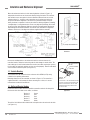
System Overview
TheBannerA-GAGE
®
MINI-ARRAYmeasuringlightscreenisidealforapplications
suchason-the-flyproductsizingandprofiling,edge-guidingandcenter-guiding,loop
tensioningcontrol,holedetection,partscounting,dieejectionverification,andsimilar
uses.
AtypicalMINI-ARRAYSystemconsistsoffivecomponents:
•aControllermodule,
•anemitterandcorrespondingreceiver,and
•twointerconnectingcables.
Sensorsareavailableinarraylengthsfrom6"to4'(in6"increments),plus5'and6'
arraymodels,aslistedonpage7.Sensorsareavailablewitheither9.5mm(3/8")or
19.1mm(3/4")beamspacing,whichtranslatestoeither32or16beamsperfootof
arraylength.Sensorswith3/8"beamspacinghaveasensingrangeofupto6m(20').
Sensorswith3/4"beamspacinghaveasensingrangeofupto17m(55');5'and6'
arrayshaveshorterrange(seeSpecifications).
Box Profiling
Paint Booth
Profiling
Edge Guiding
Inspection Applications
Figure 1-1. Typical MINI-ARRAY Applications
1. System Overview

4 P/N 43298 rev. E
Banner Engineering Corp. •Minneapolis,MNU.S.A.
www.bannerengineering.com•Tel:763.544.3164
MINI-ARRAY
®
InstructionManual
System Overview
1.1 System Features
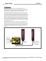
Built-infeaturessimplifytheoperationoftheA-GAGEMINI-ARRAYsystem.
Programmablebeamblankingaccommodatesmachinecomponentsorotherfixtures
thatmustremaininormovethroughthelightscreen.Blankingissetbyusingthe
includedconfigurationsoftware.SeeSection5.5.4formoreinformation.
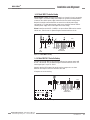
Built-indiagnosticprogrammingandeasy-to-seeindicatorsonthesensorsandthe
controlmodulemakealignmentandtroubleshootingeasy(Figure1-2).Theemitter
hasaredLEDthatsignalsproperoperation.ThereceiverhasthreebrightLEDs:green
signalsthatthesensorsareproperlyaligned;yellowsignalsmarginalalignment;and
redsignalsmisalignmentorablockedcondition.Thecontrolmodulehassevenstatus
indicators:5redLEDssignalwhenoutputsareconducting(seeSection3formore
information),Alarmoutputconducting,andgatesignalreceived;agreenLEDsignals
thatthesensorsareproperlyaligned.DIAG1,2,and3LEDsindicatesystemstatus.A
keytothediagnosticscodesisprintedonthesideofthecontrolmoduleforsimplified
troubleshooting(seeSection6.3).
TheMINI-ARRAYSystemprovidesawideselectionofsensingandoutputoptions,
including:measurement(“scananalysis”)modesandscanningmethodsthatcan
determinethetargetobject’slocation,overallsize,totalheightortotalwidth.Scanning
maybecontinuousorcontrolledbyahostprocesscontrolleroragatesensor.Some
models(MAC1,MACP,MACN)supportRS-485,whereupto15systemsmaybe
networked.
Figure 1-2. A-GAGE MINI-ARRAY System features
Emitter
DIN-Rail-Mountable Control Module
Receiver
MINI-ARRAY
CONTROLLER
2 - TX
3 - RX
5 - COM
RS-232
RS-232
MAC-1
OUT 1
ALARM
GATE
DIAG 1
DIAG 2
DIAG 3
ALIGN
POWER
Red Discrete
Output #1 LED
Red
Operational
LED
Green Alignment LED
Red Blocked LED
Yellow Marginal
Alignment LED
Red Alarm
(Discrete Output #2) LED
Red Gate LED
Green Align LED
RS-232 Port
15 14 13 12 11 10 9 8 7 6 5 4 3 2 1
15
30V
150mA
Max.
ALARM
500mA
Max
OUT 1
WH BK BU
5 Wires
BR-+
RS485
-+
10-30V DC
GATE
L2 L1
16-30V DC
1.2A Max.
14 13 12 11 10 9 8 7 6 5 4 3 2 1
T/RT/R DRN COM +12V F1
EMTR RCVR

P/N 43298 rev. E 5
Banner Engineering Corp. •Minneapolis,MNU.S.A.
www.bannerengineering.com•Tel:763.544.3164
MINI-ARRAY
®
InstructionManual
System Overview
1.1.1 Model-Specific Features
Models MAC-1, MACN-1, and MACP-1
•SupportsserialcommunicationwithahostcomputerorPLCviaRS-232orRS-485
interface;enablesacomputerorPLCtoprocessscandataand/orinitiatescans;
serialdatamaybeeitherASCIIorbinary.
•Upto15controllersmaybeassignedseparateIDsandplacedonRS-485partyline.
•MAC-1:Twooutputs:onereedrelayandoneNPNtransistoroutput;eitheroutput
maybeinverted(i.e.,programmedfornormallyopenornormallyclosed).
• MACN-1 and MACP-1:Twodiscreteopen-collectorPNP(currentsourcing)orNPN
(currentsinking)transistoroutputs,dependingonmodel.
Models MACV-1 and MACI-1
•AnalogoutputnullandspancanbeadjustedviaPCinterfaceandsuppliedsoftware.
•Analogoutputsignalcanhaveeitherarisingorfallingslope.
•Analogoutputswillautomaticallyadjusttosensorlength.
•Discreteoutputisanopen-collectorNPN(currentsinking)thatcanbeusedasan
alarm,atrigger,orusedwithanAnalysisModeSelection(outputcapableofbeing
invertedinAnalysisMode).
•MACV-1: Twolinearsourcinganalogvoltageoutputs(0to10volts)andoneNPN
transistoroutput.
•MACI-1: Twolinearsinkinganalogcurrentoutputs(4to20mA)andoneNPN
transistoroutput.
Models MAC16N-1 and MAC16P-1
•Twoadditionalmeasurementmodes:
TRNmodecountsthenumberofclear-to-blockedandblocked-to-cleartransitions;
SEGmodepartitionsthearrayintoupto16regions.
•Controllerhasflexibleblankingcapabilitieswithunlimitedblankingconditions.
Blankingmaybesetautomatically(AutoBlanking)orspecifiedusingthesuppliedPC
software.
•
MAC16N-1:16discreteopen-collectorNPN(currentsinking)transistoroutputs.
• MAC16P-1:16discreteopen-collectorPNP(currentsourcing)transistoroutputs.

6 P/N 43298 rev. E
Banner Engineering Corp. •Minneapolis,MNU.S.A.
www.bannerengineering.com•Tel:763.544.3164
MINI-ARRAY
®
InstructionManual
System Overview
1.1.2 Sensing Response
Sensingresponseisafunctionofthenumberofbeamsinterrogated(i.e.,steps)per
scanofthearray.Thetimeperstepis55µs(0.000055seconds).Asaresult,dense
arrays(i.e.,3/8"beamspacing)yieldthehighestsensingresolution,whilearrayswith
wider(3/4")beamspacingofferfastersensingresponse.
1.1.4 Supplied System Software
Thesuppliedsoftwareprogram,usedtoconfigureeachSystemcontrolmodule,may
berunonanyPCrunningWindows
®
XP, Vista, or 7.Themenu-driven
programwalkstheuserthroughthemanyscanningandoutputoptions.Afterthe
desiredoptionsareselected,theusercansavethecombinationofselectionsina
ParameterSetupFile(PSF),andstoreitinthecontrolmodule’snon-volatilememory.
AnynumberofPSFsmaybestoredinthecomputerandrecalledasneeded.
Thesoftwarealsoprovidesalignmentanddiagnosticsroutines.AnAlignmentscreen
displaystheindividualstatusofeachbeaminthelightscreen,aswellasthetotal
numberofbeamsintheSystem,andtotalsofbeamsblocked,made,andblanked.
Built-insystemdiagnosticscanbeusedtoassessemitterandreceiverhardware
errors.

P/N 43298 rev. E 7
Banner Engineering Corp. •Minneapolis,MNU.S.A.
www.bannerengineering.com•Tel:763.544.3164
MINI-ARRAY
®
InstructionManual
System Overview
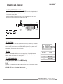
1.2 System Components
1.2.1 Emitter and Receiver Models
Figure 1-3. MINI-ARRAY system components
Quick-Disconnect
Cables
DIN-Rail-Mountable
Control Module
User-Supplied PC
Configure and monitor the System
with the supplied software and
a PC-compatible computer (see
Section 1.1.4).
Emitter Receiver
1.2.2 Controller-to-Sensor Cables
2requiredpersystem
19.1 mm (3/4") beam spacing – 16 beams/foot
Emitter / Receiver
Models
Array Length
Total
Beams
BMEL616A / BMRL616A
133mm(5.25") 8
BMEL1216A / BMRL1216A
286mm(11.25") 16
BMEL1816A / BMRL1816A
438mm(17.25") 24
BMEL2416A / BMRL2416A
591mm(23.25") 32
BMEL3016A / BMRL3016A
743mm(29.25") 40
BMEL3616A / BMRL3616A
895mm(35.25") 48
BMEL4216A / BMRL4216A
1048mm(41.25") 56
BMEL4816A / BMRL4816A
1200mm(47.25") 64
BMEL6016A / BMRL6016A
1505mm(59.25") 80
BMEL7216A / BMRL7216A
1810mm(71.25") 96
9.5 mm (3/8") beam spacing – 32 beams/foot
BMEL632A / BMRL632A
143mm(5.62") 16
BMEL1232A / BMRL1232A
295mm(11.62") 32
BMEL1832A / BMRL1832A
448mm(17.62") 48
BMEL2432A / BMRL2432A
600mm(23.62") 64
BMEL3032A / BMRL3032A
752mm(29.62") 80
BMEL3632A / BMRL3632A
905mm(35.62") 96
BMEL4232A / BMRL4232A
1057mm(41.62") 112
BMEL4832A / BMRL4832A
1210mm(47.62") 128
BMEL6032A /BMRL6032A
1514mm(59.62") 160
BMEL7232A / BMRL7232A
1819mm(71.62") 192
Model Length QD Connector
QDC-515C
4.6m(15')
5-pinMini-style
straight
QDC-525C
7.6m(25')
QDC-550C
15.2m(50')
MAQDC-575C
22.7m(75')
MAQDC-5100C
30.3m(100')
MAQDC-5125C
37.9m(125')
MAQDC-5150C
45.5m(150')

8 P/N 43298 rev. E
Banner Engineering Corp. •Minneapolis,MNU.S.A.
www.bannerengineering.com•Tel:763.544.3164
MINI-ARRAY
®
InstructionManual
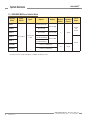
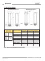
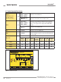
DimensionsforallMACSeriesControllerslistedaboveare:110x100x75mm(4.3"x3.9"x3.0");seeFigure2-2.
*SeeSection5.5.3foradetaileddescriptionofavailablescananalysismodes.
System Overview
1.2.3 MINI-ARRAY MAC Series Controller Models
Controller
Model
Supply
Voltage
Inputs Output 1 Output 2
Scan
Analysis
Modes*
PSF
Parameter
Diskette
Serial
Output
MAC-1
16to30Vdc
1SensorPair
1Gate
DiscreteReedRelay
DiscreteNPN
8 43989
RS-232
and
RS-485
MACN-1
DiscreteNPN
MACP-1
DiscretePNP DiscretePNP
MACV-1
(2)Analog
0to10VdcSourcing
DiscreteNPN
RS-232
MACI-1
(2)Analog
4to20mASinking
MAC16N-1
16DiscreteNPNOutputs
10 59114
MAC16P-1
16DiscretePNPOutputs

P/N 43298 rev. E 9
Banner Engineering Corp. •Minneapolis,MNU.S.A.
www.bannerengineering.com•Tel:763.544.3164
MINI-ARRAY
®
InstructionManual
Specifications
2. Specifications
2.1 Emitter and Receiver Specifications
Emitter/Receiver Range
9.5 mm (3/8") Beam Spacing
0.6to6.1m(2to20')forsensors<4'
0.6to4.6m(2to15')forsensors>4'
NOTE:Maximumrangeisspecifiedatthe
pointwhere3xexcessgainremains.
19.1 mm (3/4") Beam Spacing
0.9to17m(3to55')forsensors<4'
0.9to14m(3to45')forsensors>4'
NOTE:Maximumrangeisspecifiedatthepoint
where3xexcessgainremains.
Minimum Object Sensitivity
9.5 mm (3/8") Beam Spacing
19.1mm(0.75")
InterlacedMode:12.7mm(0.5")*
*NOTE:Assumessensingisinmiddle
one-thirdofscanningrange.
19.1 mm (3/4") Beam Spacing
38.1mm(1.5")
InterlacedMode:25.4mm(1.0")*
*NOTE:Assumessensingisinmiddle
one-thirdofscanningrange.
Sensor Scan Time
55microsecondsperbeam,plus1millisecondprocessingtimeperscan.(Assumesstraightscan,
continuousscan,andTBB mode;seeSection5.5.5ScanningModesforfurtherinformation.)
Power Requirements
Emitter
0.10amps@12Vdc
NOTE:Maximumcurrentisfora6'sensor.
Receiver
9.5mm(3/8")beams:0.75amps@12Vdcmax.
19.1mm(3/4")beams:0.50amps@12Vdcmax.
NOTE:Maximumcurrentisfora6'sensor.
Connections
Emitterandreceiverconnecttocontrollerusingtwo5-conductorquick-disconnectcables(one
eachforemitterandreceiver),orderedseparately.SeeSection1foravailablecablelengths.
Cablesmeasure8.1mm(0.32")dia.,andareshieldedandPVC-jacketed;conductorsare20-gauge.
•UseonlyBannercables,whichincorporatea"“twistedpair”fornoiseimmunityonRS-485data
communicationlines.
•Emitterandreceivercablesmaynotexceed250'each.
Status Indicators
(See Section 6.1 for more
information)
Emitter
RedLEDlightsforproperoperation
Receiver
Green:sensorsaligned(>3xexcessgain)
Yellow:marginalalignment(1x-3xexcessgain)
Red:sensorsmisalignedorbeam(s)blocked
Environmental Rating
NEMA4,13(IECIP65)
Construction
Aluminumhousingwithblackanodizedfinish;acryliclenscover
Operating Conditions
Temperature:
-20°to70°C(-4°to158°F)
Max. rel. humidity:
95%(non-condensing)

10 P/N 43298 rev. E
Banner Engineering Corp. •Minneapolis,MNU.S.A.
www.bannerengineering.com•Tel:763.544.3164
MINI-ARRAY
®
InstructionManual
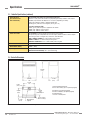
2.2 Emitter and Receiver Dimensions
Specifications
With mounting bracket flanges “out”
Figure 2-1. Emitter and receiver mounting dimensions and defined area location
With mounting bracket flanges “in”
L2
L1
X
18.3 mm
(0.72")
2.5 mm
(0.10")
38.1 mm Square
(1.50")
10.2 mm
(0.40")
L3
X
(Distance to First
Optical Channel)
9.5 mm
(3/8")
Beam
Spacing
38.1mm
(1.50")
19.1 mm
(3/4")
Beam
Spacing
42.9mm
(1.69")
Emitter/Receiver Models
Housing Length Distance Between Bracket Holes
L1 L2 L3
BMEL6..A / BMRL6..A
201.0mm(7.9") 233.9mm(9.21") 177.0mm(6.97")
BMEL12..A / BMRL12..A
356.0mm(14.0") 389.7mm(15.35") 332.8mm(13.1")
BMEL18..A / BMRL18..A
505.0mm(19.9") 538.7mm(21.22") 481.8mm(18.97")
BMEL24..A / BMRL24..A
659.0mm(26.0") 693.2mm(27.31") 636.3mm(25.05")
BMEL30..A / BMRL30.A
810.0mm(31.9") 843.5mm(33.23") 786.6mm(30.97")
BMEL36..A / BMRL36.A
963.0mm(37.9") 997.4mm(39.29") 940.5mm(37.0")
BMEL42..A / BMRL42.A
1115.0mm(43.9") 1148.0mm(45.2") 1091.0mm(43.0")
BMEL48..A / BMRL48.A
1267.0mm(49.9") 1301.0mm(51.2") 1244.0mm(49.0")
BMEL60..A / BMRL60..A
1572.0mm(61a.9") 1606.0mm(63.2") 1549.0mm(61.0")
BMEL72..A / BMRL72..A
1877.0mm(73.9") 1910.0mm(75.2") 1853.0mm(73.0")

P/N 43298 rev. E 11
Banner Engineering Corp. •Minneapolis,MNU.S.A.
www.bannerengineering.com•Tel:763.544.3164
MINI-ARRAY
®
InstructionManual
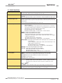
2.3 Controller Specifications
Specifications
Power Requirements
16to30Vdc@1.25ampsmax.(seecurrentrequirementsforsensors);
Controlleralone(withoutsensorsconnected)requires0.1amp.
Inputs
MINI-ARRAYsensorinput(5connections);emitterandreceiverwireinparalleltofive
terminals.
GATEinput:Optically-isolated,requires10to30Vdc(7.5Kinputimpedance)forgatesignal.
System Response Time
Outputsarenotactivefor5secondsaftersystempowerup.Maximumresponsetimeforthe
discreteoutputsistwoscancycles.Ascancycleincludesasensorscanplusanyserialdata
transmission.
Serialtransmission(ifactivated)followseverysensorscan.
Discrete Outputs
MAC-1:
Output1(OUT1):Reedrelaycontactrated125Vac/dcmax.,10VAmax.resistive
load(non-inductive).
Output2(ALARM):OpencollectorNPNtransistorrated30Vdcmax.,150mAmax,
short-circuitprotected(maybeconfiguredasaseconddataanalysisoutput,system
alarmoutput,orscantriggeroutputforaparallelarray).
OFF-STATELeakageCurrent:<10µA@30Vdc
ON-STATESaturationVoltage:<1Volt@10mA,<1.5Volt@150mA
MACN-1: (2)OpencollectorNPNtransistoroutputs.
MACP-1:(2)OpencollectorPNPtransistoroutputs.
Transistorrated30Vdcmax.,150mAmax,shortcircuitprotected(maybe
configuredasaseconddataanalysisoutput,systemalarmoutput,orscantrigger
outputforaparallelarray).
OFF-STATELeakageCurrent<10µA@30Vdc
ON-STATESaturationVoltage<1Volt@10mA,<1.5Volt@150mA
MACV-1/MACI-1:Alarm:OpencollectorNPNtransistorrated30Vdcmax.150mAmax,short
circuitprotected.
(maybeconfiguredasadataanalysisoutput,systemalarmoutput,orscan
triggeroutputforaparallelarray)
OFF-STATELeakageCurrent:<10µA@30Vdc
ON-STATESaturationVoltage:<1Volt@10mA,<1.5Volt@150mA
MAC16P-1:SixteenopencollectorPNPtransistoroutputs.
MAC16N-1: SixteenopencollectorNPNtransistoroutputs.
30Vdcmax,150mAmax.,shortcircuitprotected.
OFF-STATEleakagecurrent:<10µA
ON-STATESaturationVoltage:<1Volt@10mA;<1.9V@150mA
Analog Outputs
MACV-1: (2) 0-10VoltssourcingadjustableNullandSpan(20mAcurrentlimit).
MACI-1: (2)4-20mAcurrentsinkingadjustableNullandSpan(16to30Vinput).
Resolution:
SpanminusNull,dividedbythenumberofsensorchannels
Linearity:
0.1%ofFullScale
Temp. Var.:
0.01%ofFullScale/°C
Serial Data Outputs
All Models: RS-232,ASCIIorbinarydataformat.
Baudrate:9600,19.2K,or38.4K8databits,1startbit,1stopbit,evenparity.
Cleardatamaybesuppressed;headerstringmaybesuppressedinbinary
format.
MAC-1, MACN-1,
and MACP-1:
Upto15ControllersmaybegivenuniqueaddressforRS-485partyline.
Controller Programming
ViaRS-232toPC-compatiblecomputerrunningWindows
®
.XP, Vista, or 7
operatingsystemandusingBanner-suppliedsoftware(seeusermanual).

12 P/N 43298 rev. E
Banner Engineering Corp. •Minneapolis,MNU.S.A.
www.bannerengineering.com•Tel:763.544.3164
MINI-ARRAY
®
InstructionManual
Status Indicators
(See Section 6.2 for
more information)
The following status LEDs are located on the front panel:
OUTPUT1(red)(nameandfunctionvarydependingonmodel):Indicatesactiveoutput
ALARM(red):IndicatesthatOutput2or16isactive(dependingonmodel)
GATE(red):IndicatesvoltageisappliedtoGATEinput
ALIGN(green):Indicatessensoraligned(excessgain>1x)
Plus three diagnostic LEDs:
DIAG1(green):Indicatespowerisappliedtothemodule
DIAG2(red):Indicatesreceiverfailure
DIAG3(red):Indicatesemitterfailure
Sensor Scan Time
For all models:
55microsecondsperbeamplusprocessingtime.
Theprocessingtimeisdependentonthescananalysisandthenumberofactiveoutputs.
Thistimingassumesastraightscan,continuous,andTBBmode.
MAC-1, MACN-1 & MACP-1:1millisecondprocessingtime.
MACV-1 & MACI-1:
1.5millisecondsprocessingtime.
MAC16N-1 & MAC16P-1:2.3to7millisecondsprocessingtime.
Construction
Polycarbonate
Environmental Rating
NEMA1(IP20)
Operating Conditions
Temperature:
-20°to+70°C(-4°to+158°F)
Maximum Relative Humidity:95%(non-condensing)
2.4 Controller Dimensions
Figure 2-2. Control module dimensions and mounting hole locations
75.0 mm
(2.95")
60.8 mm
(2.40")
7.1 mm
(0.28")
Din mounting tab
(supplied)
Slot for screws (2)
M3.5 x 0.6 mm (2)
35.0 mm
(1.38")
Din mounting slot
100.0 mm
3.94"
85.3 mm
3.36"
7.4 mm
(0.29")
110.0 mm
(4.33")
Combo Head (Phillips/Slotted Screws
M3.5 x 0.6 mm x 14 mm (2 ) (#6 x 0.5" equivalent) (supplied)
M3.5 Washers (2) (#6 equivalent) (supplied)
M3.5 mm x 0.6 mm Nuts (2) (#6 equivalent) (supplied)
Recommended torque is
16-20 in -lbs on mounting screws
Specifications
2.3 Controller Specifications (continued)

P/N 43298 rev. E 13
Banner Engineering Corp. •Minneapolis,MNU.S.A.
www.bannerengineering.com•Tel:763.544.3164
MINI-ARRAY
®
InstructionManual
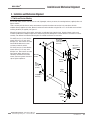
Installation and Mechanical Alignment
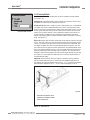
3.1 Emitter and Receiver Mounting
BannerMINI-ARRAYemittersandreceiversaresmall,lightweight,andeasytomount;themountingbrackets(supplied)allow±30
degreesrotation.
Fromacommonpointofreference,makemeasurementstopositiontheemitterandreceiverinthesameplanewiththeir
midpointsdirectlyoppositeeachother.MounttheemitterandreceiverbracketsusingtheM4x0.7x14mmboltsandassociated
mountinghardware(allsupplied).SeeFigure3-1.
Althoughtheinternalcircuitryoftheemitterandreceivercanwithstandheavyimpulseforces,vibrationisolatorscanbeused
insteadoftheM4boltstodampenimpulseforcesandpreventpossibledamagefromresonantvibrationoftheemitterorreceiver
assembly.TwodifferentAnti-VibrationMountingKitsareavailablefromBannerasaccessories.
Figure 3-1. MINI-ARRAY emitter and receiver mounting hardware
Emitter
or
Receiver
Mounting
Mounting
Bracket
Surface
M4
Nut (4)
Washer (2)
with Compression
Slotted Hex Head
M4 x 10 mm
Bracket
Mounting
Nut
Washer
M4 x 14 mm
Screw with Flat
Washer
Compression
Washer (4)
Torque to
12 in. lbs.
(1.3 N-m)
3. Installation and Mechanical Alignment
P/N48955consistsof4anti-vibration
mounts(M4x0.7x9.5mm)and8
M4Kepsnuts.Thesemountsaremade
fromBUNA-Nrubberandaremore
resistanttochemicalsandoils.
P/N12847consistsof4anti-vibration
mounts(M4x0.7x9.5mm)and8
M4Kepsnuts.Thesemountsaremade
fromnaturalrubber,whichareless
chemicallyresistantthanthe48955
mounts,buthaveagreatersheerforce
specathighertemperature.

14 P/N 43298 rev. E
Banner Engineering Corp. •Minneapolis,MNU.S.A.
www.bannerengineering.com•Tel:763.544.3164
MINI-ARRAY
®
InstructionManual
Installation and Mechanical Alignment
Figure 3-2. MINI-ARRAY emitter and receiver mounting bracket dimensions
Mounttheemitterandreceiverintheirmountingbrackets(showninFigure3-1),
andpositiontheredlensesofthetwounitsdirectlyfacingeachother.Theconnector
endsofbothsensorsmustpointinthesamedirection.Measurefromoneormore
referenceplanes(i.e.,thefloor)tothesamepointsontheemitterandreceiverto
verifytheirmechanicalalignment.Ifthesensorsarepositionedexactlyverticalor
exactlyhorizontal,acarpenter’slevelmaybeusefulforcheckingalignment.Extending
astraight-edgeorastringbetweenthesensorsmayhelpwithpositioning.Alsocheck
byeyeforline-of-sightalignment.Makeanynecessaryfinalmechanicaladjustments,
andhand-tightenthebrackethardware.SeeSection5forinformationonalignment
indicatorsandtheuseofthealignmentsoftwaresuppliedwiththecontroller.
Connecttheshieldedcablestotheemitterandreceiver,androutethemtothe
controllerlocation.Followthelocalwiringcodeforlow-voltagedccontrolcables.The
samecabletypeisusedforbothemitterandreceiver(twocablesrequiredpersystem).
Cutthecablestolengthaftermakingsuretheyareroutedproperly.Removecablebraid
atthecontrollerconnectionpoints(seeFigure3-4).
3.2 Controller Mounting
ThecontrollermustbeinstalledinsideanenclosurewithaNEMA(orIEC)rating
suitablefortheoperatingenvironment.
MountingdimensionsforthecontrollerareshowninFigure2-2.Thecontrolleris
suppliedwithM3.5x0.6hardwarefordirectmountingtoasurface,oritcanbe
mountedontostandard35mmDINrail.
3.3 Emitter and Receiver Hookups
Emitterandreceivercablesconnectinparalleltocontrollerterminals#4through#8.
Connectthewiresfrombothsensorcables,asfollows:
Terminal4 Brown
Terminal5 Blue
Terminal6 Bare
Terminal7 Black
Terminal8 White
Trimoffthefoilshieldandthebraidedshieldatthepointwherethewiresexitthecable
(seeFigure3-4).
The“drainwire”istheuninsulatedstranded
wirewhichrunsbetweenthebraidedshield
andthefoilshield.Removethefoilshield
andbraidedshieldatthepointwherethe
wiresexitthecable.
Figure 3-4. Emitter/receiver cable
preparation
Tr im braided shield flush
with cable
Tr im foil shield flush
with cable
Uninsulated
drain wire
Emitter or
Receiver
8.1 mm
(0.32") max.
0.5" (13 mm) radius minimum bend
71 mm
2.8"
Figure 3-3. Quick-disconnect cable
clearances

P/N 43298 rev. E 15
Banner Engineering Corp. •Minneapolis,MNU.S.A.
www.bannerengineering.com•Tel:763.544.3164
MINI-ARRAY
®
InstructionManual
Installation and Mechanical Alignment
Figure 3-5. Model MAC-1 hookup
1
+
–
+
–
10-30V dc
Gate
16-30V dc
1.2 A Max.
234
5678
9
101112131415
F1
BROWN
BLUE
DRAIN (BARE)
BLACK
WHITE
EMITTER and
RECEIVER CABLES
V– V+
RS485
500 mA
Max.
Out 1
30V
150 mA
Max.
ALARM
Power
3.4 Controller Wiring and Output Hookups
CableclearancedimensionsforthearraysareshowninFigure3-3.
Controllerconnectionsaremadeviathewiringterminalsalongthefrontsurface
ofeachmodule.Emitterandreceiverhookupsandcontrolleroutputsareshownin
Figures3-5through3-11.
3.4.1 Model MAC-1 Controller Hookup
Output 1:Controllerterminals#9and#10(OUT1)arereedrelaycontactsrated
at125Vac/dcmax.,10VAmax.resistive(i.e.,non-inductive)load.Itmaybe
programmedaseithernormallyopenornormallyclosed.
Alarm:Controllerterminal#15(Alarm)isanopen-collectorNPNtransistorswitch
ratedat30Vdcmax.,150mAmax.Itisprotectedagainstoverloadandshortcircuits.
3.4.2 Model MACP-1 Controller Hookup
Output 1:Controllerterminal#9(OUT1)isanopen-collectorPNPtransistorswitch
ratedat30Vdcmax.,150mAmax.Itisprotectedagainstoverloadandshortcircuits.
Alarm:Controllerterminal#15(ALARM)isanopen-collectorPNPtransistorswitch
ratedat30Vdcmax.,150mAmax.Itisprotectedagainstoverloadandshortcircuits.
Bothoutputsarecurrentsourcing.
Figure 3-6. Model MACP-1 hookup
1
+
–
+
–
10-30V dc
Gate
16-30V dc
1.2 A Max.
234
5678
9
101112131415
F1
BROWN
BLUE
DRAIN (BARE)
BLACK
WHITE
EMITTER and
RECEIVER CABLES
V- V+
RS485
Com
30V
150 mA
Max.
ALARM
30V
150 mA
Max.
Out
Power
V+ V+

16 P/N 43298 rev. E
Banner Engineering Corp. •Minneapolis,MNU.S.A.
www.bannerengineering.com•Tel:763.544.3164
MINI-ARRAY
®
InstructionManual
Installation and Mechanical Alignment
1
+
–
+
–
10-30V dc
Gate
16-30V dc
1.2 A Max.
234
5
678
9
10131415
F1
BROWN
BLUE
DRAIN (BARE)
BLACK
WHITE
EMITTER and
RECEIVER CABLES
V- V+
RS485
Out 1
30V
150 mA
Max.
30V
150 mA
Max.
ALARM
Power
12 11
Com
1
+
–
10-30V dc
Gate
16-30V dc
1.2 A Max.
234
5678
9
10131415
F1
BROWN
BLUE
DRAIN (BARE)
BLACK
WHITE
EMITTER and
RECEIVER CABLES
V- V+
30V
150 mA
Max.
ALARM
0-10V
10 mA
V out 2
Power
12 11
Com Com
0-10V
10 mA
Max.
V out 1
Figure 3-7. Model MACN-1 hookup
Figure 3-8. Model MACV-1 hookup
3.4.3 Model MACN-1 Controller Hookup
Output 1:Controllerterminal#9(OUT1)isanopen-collectorNPNtransistorswitch
ratedat30Vdcmax.,150mAmax.Itisprotectedagainstoverloadandshortcircuits.
Alarm:Controllerterminal#15(ALARM)isanopen-collectorNPNtransistorswitch
ratedat30Vdcmax.,150mAmax.Itisprotectedagainstoverloadandshortcircuits.
Bothoutputsarecurrentsinking.
3.4.4 Model MACV-1 Controller Hookup
Voltage outputs 1 and 2:Controllerterminals#9(Vout1)and#13(Vout2)are
analogvoltageoutputs.TheloadforanalogvoltageOutput#1shouldbetiedacross
terminals#9and#10.TheloadforanalogvoltageOutput#2shouldbetiedacross
terminals13and14.Bothswitchesareratedat10Vdcmax.,10mAmax.Both
outputsarevoltagesourcing.
Alarm:Controllerterminal#15(ALARM)isanopen-collectorNPNtransistorratedat
30Vdcmax.,150mAmax.,currentsinking.

P/N 43298 rev. E 17
Banner Engineering Corp. •Minneapolis,MNU.S.A.
www.bannerengineering.com•Tel:763.544.3164
MINI-ARRAY
®
InstructionManual
Installation and Alignment
3.4.5 Model MACI-1 Controller Hookup
Current outputs 1 and 2:Controllerterminal#9(Iout1)and#13(Iout2)areanalog
currentoutputs.TheloadforanalogcurrentOutput#1shouldbeconnectedbetween
anexternal16to30Vdcpowersupplyandterminal#9.Theloadforanalogcurrent
Output#2shouldbeconnectedbetweenanexternal16to30Vdcpowersupply
andterminal13.Theloadexternalpowersupplyreturnshouldbecommonwiththe
controllerpowersupplyreturn.Bothoutputsarecurrentsinking.
Alarm:Controllerterminal#15(ALARM)isanopen-collectorNPNtransistorratedat
30Vdcmax.,150mAmax.Itisprotectedagainstoverloadandshortcircuits.
1
+
–
10-30V dc
Gate
16-30V dc
1.2 A Max.
234
5678
9
10131415
F1
BROWN
BLUE
DRAIN (BARE)
BLACK
WHITE
EMITTER and
RECEIVER CABLES
V- V+
30V
150 mA
Max.
ALARM
Power
12 11
Com Com
4-20 mA
I out 2
4-20 mA
I out 1
3.4.6 Model MAC16P-1 Controller Hookup
Terminals#15through#30areopen-collectorPNPtransistoroutputsratedat30V
dcmax.,150mAmax.Theyareprotectedagainstoverloadandshortcircuits.The
isolatedgateinputisatpins11and12.
Controllerterminal#15(output#16)maybeusedasanoutputorasanalarm.
Wheneverthisoutputisactive,theredAlarmLEDisON.
Alloutputsarecurrentsourcing.
Figure 3-9. Model MACI-1 hookup
1
+
–
10-30V dc
Gate
16-30V dc
1.2 A Max.
234
5
678
9
101314
15 30
F1
BROWN
BLUE
DRAIN (BARE)
BLACK
WHITE
EMITTER and
RECEIVER CABLES
V- V+
Power
12 11
NC NC NC NC
through
16 Solid-state Ouputs
V+
150 mA Max each
Figure 3-10. Model MAC16P-1 hookup

18 P/N 43298 rev. E
Banner Engineering Corp. •Minneapolis,MNU.S.A.
www.bannerengineering.com•Tel:763.544.3164
MINI-ARRAY
®
InstructionManual
Figure 3-12. DB9 serial connector
3.5 System Power
Connecta16to30Vdcsourcetocontrollerterminals#1(V+)and#2(V–).Connect
agoodearthgroundtoterminal#3.Agoodearthgroundisimportantforproviding
electricalandRFnoiseimmunitytotheMINI-ARRAYSystem.Thedcpowersource
mustsupply1.25amps(worstcase)whenusingthelongest(6')sensors.See
Specifications(Section2)formoreinformation.
3.6 Gate
Connectaswitched10to30Vdcsourceasagatinginput(ifrequired)between
controllerterminal#11(+)and#12(-).Voltageistypicallyswitchedbytheopen-
collectoroutputtransistorofadcsensingdevice.
3.7 Serial Communication
RS-485 (Models MAC-1, MACP-1, and MACN-1 only)
ConnectRS-485lines(ifused)toterminals#13(+)and#14(-).
RS-232
PrepareanRS-232cableusingaDB-9maleconnectorwiththeconnectionsshownin
Figure3-12.
NOTE: DO NOT use a “null modem” RS-232 cable.
RS-232
5
23
2- TX
3- RX
5- COM
DB-9 Pin #
Function
Ground (GND)
Receive (RX)
Transmit (TX)
5
3
2
Installation and Alignment
3.4.7 Model MAC16N-1 Controller Hookup
Terminals#15through#30areopen-collectorNPNtransistoroutputsratedat
30Vdcmax.,150mAmax.Theyareprotectedagainstoverloadandshortcircuits.
Alloutputsarecurrentsinking.
Controllerterminal#15(output#16)maybeusedasanoutputorasanalarm.
Wheneverthisoutputisactive,theredAlarmLEDisON.
1
+
–
10-30V dc
Gate
16-30V dc
1.2 A Max.
234
5
678
9
101314
F1
BROWN
BLUE
DRAIN (BARE)
BLACK
WHITE
EMITTER and
RECEIVER CABLES
V- V+
Power
12 11
NC NC NC NC
15 30
through
16 Solid-state Ouputs
150 mA Max each
Figure 3-11. Model MAC16N-1 hookup

P/N 43298 rev. E 19
Banner Engineering Corp. •Minneapolis,MNU.S.A.
www.bannerengineering.com•Tel:763.544.3164
MINI-ARRAY
®
InstructionManual
Software Installation
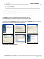
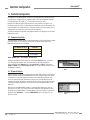
4. Software Installation
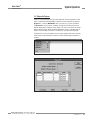
The Parameter Setup Software CD includes an installation program that quickly and easily loads the MINI-ARRAY configuration program into the computer.
The MINI-ARRAY configuration program requires approximately 50 MB of hard disk space. Install as follows:
1. Use the Parameter Setup Software CD included with the controller, or download (www.bannerengineering.com) per the following:
Models MAC-1, MACI-1, MACN-1, MACP-1, MACV-1: CD P/N 75877
Models MAC16N-1, MAC16P-1: CD P/N 75878
2. Insert the Software CD into the CD drive.
If the program does not auto-start, browse to your CD drive, click Setup.exe, then select START, then select
RUN.
2. The Welcome dialog box will appear. Select Next, and follow the prompts in the dialog boxes as they appear.
4. The installation program then decompresses the files. A status dialog box monitors the progress of the installation.
5. An Installation Completed dialog box appears. Select OK. Reboot your computer for the changes to take effect.
After the software is installed, a MINI-ARRAY shortcut icon is placed on your desktop. Double-click on the MINI-ARRAY icon to launch the program, then
follow the configuration and setup procedures described in Section 5 of the primary manual.
Figure 4-1. MINI-ARRAY software installation: dialog boxes

20 P/N 43298 rev. E
Banner Engineering Corp. •Minneapolis,MNU.S.A.
www.bannerengineering.com•Tel:763.544.3164
MINI-ARRAY
®
InstructionManual
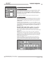
ConfigurationoftheMINI-ARRAYcontrollerisaccomplishedwithaWindows
®
menu-
styleprocedure,usingtheBanner-suppliedsoftwareandaPC-compatiblecomputer
runningWindows
®
XP, Vista, or 7.Aserialdataconnectionismade
betweenthecomputerandtheDB9connectoronthecontroller(seeFigure3-12).
ParameterSetupFiles(PSF)areprogrammedconfigurationsthatcanbestoredinthe
controlmodule’snon-volatilememory.TheBannersoftwarecanstorevariousPSFsin
computerfilesforinstantcall-upofaparticularconfiguration.
TheBannersoftwarealsoprovidestwoadditionalfeatures:AnAlignmentscreenanda
Diagnosticsscreen
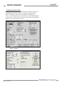
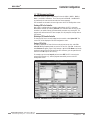
5.1 Communications Setup
TheMINI-ARRAYsoftwarepermitsserialcommunicationviaRS-232betweentheMAC
controllerandthePC.TheminimumconnectionstotheDB-9connectoronthe
MINI-ARRAYControllersareasfollows:
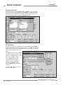
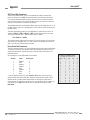
Figure 5-1. MINI-ARRAY software Option
menu
Figure 5-2. MINI-ARRAY software Main
menu
NOTE: DO NOT use a “null modem” RS-232 cable.
ConfiguretheCOMportofthePCbyfirstselectingtheOptionsmenu(seeFigure
5-1).Theprogramsupportsserialcommunicationviathe.COM1-COM20.port.
ofthecomputer.SelectOptions,thenselectSerial Port(orEnter).Selecteither
COM1orCOM2.CheckSave Settings on Exit (ifitisnotalreadychecked)tostore
theCOMportselection.
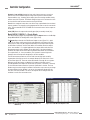
5.2 Alignment Analysis
AlignmentstatusiscontinuouslydisplayedbythegreenLEDindicatorontheReceiver
andthecontroller.Whenallunblankedbeamsareclear,andexcessgainofallbeams
ismorethan3x,thegreenalignmentindicatorswillbeON.Whentheexcessgain
ofoneormorebeamsdropstobetween3xand1x,thegreenALIGNLEDonthe
controllerwillremainON,buttheyellowLEDonthereceiverwillcomeONtoindicate
awarningofmarginalalignment.SeeSection6formoreinformationaboutsensor
alignment.
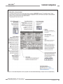
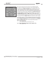
OnefeatureoftheMINI-ARRAYsoftwareisaprogramthatdisplaysthestatusof
eachbeaminthearray.Thisroutinecanbeveryhelpfulforfinalalignmentorwhen
analyzinghowtheMINI-ARRAYisviewingobjectsinthesensingarray.Tolaunchthis
program,selectAlignment...undertheMINI-ARRAYmenu(seeFigure5-2),or
presstheF3key.
Controller Configuration
5. Controller Configuration
Pin Number of DB-9 Function
2 Transmit(TX)
3 Receive(RX)
5 Ground(GND)
Page is loading ...
Page is loading ...
Page is loading ...
Page is loading ...
Page is loading ...
Page is loading ...
Page is loading ...
Page is loading ...
Page is loading ...
Page is loading ...
Page is loading ...
Page is loading ...
Page is loading ...
Page is loading ...
Page is loading ...
Page is loading ...
Page is loading ...
Page is loading ...
Page is loading ...
Page is loading ...
Page is loading ...
Page is loading ...
Page is loading ...
Page is loading ...
-
 1
1
-
 2
2
-
 3
3
-
 4
4
-
 5
5
-
 6
6
-
 7
7
-
 8
8
-
 9
9
-
 10
10
-
 11
11
-
 12
12
-
 13
13
-
 14
14
-
 15
15
-
 16
16
-
 17
17
-
 18
18
-
 19
19
-
 20
20
-
 21
21
-
 22
22
-
 23
23
-
 24
24
-
 25
25
-
 26
26
-
 27
27
-
 28
28
-
 29
29
-
 30
30
-
 31
31
-
 32
32
-
 33
33
-
 34
34
-
 35
35
-
 36
36
-
 37
37
-
 38
38
-
 39
39
-
 40
40
-
 41
41
-
 42
42
-
 43
43
-
 44
44


Banner A-GAGE MINI-ARRAY MACI-1 User manual
- Type
- User manual
- This manual is also suitable for
Ask a question and I''ll find the answer in the document
Finding information in a document is now easier with AI
Related papers
-
Banner Laser Gauging Sensors L-GAGE User manual
-
-
-
-
-
Banner T30RW-1515 User guide
-
Banner R-GAGE K50R User guide
-
-
Banner ZMX Series User guide
-
Other documents
-
 LIFX L3BEAMKITUS Installation guide
-
BEA GS-1 User guide
-
IFM OJ5131 Operating instructions
-
-
IFM OJ5038 Operating instructions
-
IFM OJ5038 Operating instructions
-
-
Potter QDC-2 Owner's manual
-
Omron ZX-GT28S41 Quick start guide
-
 Sunx NA1-11 User manual

