Page is loading ...

INSTALLATION
MANUAL CO.VERT,BLEGASGRILL JENN-AIR
COOKTOPSERIES
JGD8130&JGD8345
DIMENSIONSSHOWNINBOTHINCHESAND CENTIMETERS
*Blowermayberotatedforhorizontalorverticaldirectionbylooseningnutsaroundblowerinlet.Accessibleinsideventilation
chamber. •NOTICETO INSTALLER:Leavetheseinstructionswiththeappliance.
•NOTICETO CONSUMER:Retaintheseinstructionsforfuturereference.
REGULATOR -- APPUANCEPRESSURE
REGULATOR
TIEDOWNBOLT TIEDOWNBOLT
ONEACHEND ONEACHEND ,OVER
GREASE
BLOWERCANBE GREASE BLOWERCANBE CONTAINER
SWIVELED90° CONTAINER _WIVELED90°
29".t.1/431/4":i 1/16"
79/16"7_6"
• 19.21cm =.19.21om
Min.
15/16"4.76cm
Min.Min.
ClearanceClearance
2.38cm 2.38cm
SELECTAPPROPRIATE SELECTAPPROPRIATE
DUCTCUTOUT DUCTCUTOUT4
DUCTINGINSTALl.A- DUCTINGINSTALLA-
TIONINSTRUCTIONS). TIONINSTRUCTIONS). _EA_,E
.31/_° 0 0 _, It....... =_--'="r"_--=--_"
_5.11_ ,_g_ ,3 ,_,,_-
35,1 cm
27/8" =""-133/4" L J tl 13/16 °--m
7.3 ¢m ._4.9 cm ]O,O cm 7.327/8"_¢m _1334.93/4"cm I68.0263/4¢m " _ _-_!
INSTRUCTIONSTOINSTALLER
•Dimension"A"- Provide2"rain.(5.08cm)cabinetclearancetomotorforcoolingpurpose.
•Note-Wherepossible,6" (15.24cm)isrecommendedformotor/blowerservice.
•SideClearance-Grillsinstalledneara sidewallmustallowa minimumclearanceof8".
•Accessmustbeprovidedtoremoveandemptygreasecontainer(s). 8101 P406..60
(09-01-00)
L

InstallingCabinetryOverYourJenn.AirGrill
*A = 30" (76.2¢m) minimum vertical clearancebetween of localcodes, with the latest edition of theNational
cookingsurfaceandconstruction above theappliance. Electrical Code ANSI/NFPA No. 70 USA or currant CSA
STANDARD C22.1 Canadian ElectricalCodepart 1.
*B = 13"(33.02 cm) maximum depth of cabinets installed
above cooking top.
I Dottedlines
indicate
' rangehood
i construction
*To eliminate associated potential hazards such as
reaching over open flames, avoid use of cabinets above Cabinet Bottom
cooktop for storage space.Figure 2
CabinetsAboveCookingTop
Maximum depth of cabinets installed above cooking top is
13 inches.
CAUTION: SOME CABINETS AND BUILDING
MATERIALS ARE NOT DESIGNED TOWITHSTAND THE
HEAT PRODUCED BY THE NORMAL SAFE OPERATION
OF A LISTED APPLIANCE. DISCOLORATION OR
DAMAGE,SUCH AS DELAMINATION,MAY OCCUR.
InstallationOfAppliance
Followaccompanyingducting instructionscarefully.
This appliance isdesignedtoalways bevented outdoors.ConnectingApplianceToGasSupply
The Countertop Cutout, Cabinet Front Cutoutand Duct A TRAINED SERVICEMAN OR GAS APPLIANCE
Openingshouldbepreparedaccordingtotheillustrationon INSTALLER MUST MAKE THE GAS SUPPLY _ - ._
pages 1 and 2.CONNECTION. Leak testing of the appliance_1"_ . ''_
conducted by theinstaller according to the _ -7
Theinstallationofthis appliancemust conform withlocal instructions given.
codes or, in theabsence of local codes, withthelatest
editionoftheNationalFuelGas Code,ANSIZ223.1USAor Installamanualshutoffvalveinanaccessiblelocationinthe
currentCAN/CGA-B149 )NSTALLATION CODE. gas lineexternaltothisapplianceforthepurposeofturning
onorshuttingoffgastotheappliance.
Theelectricalsupplyrequiredis110/120Volt,A.C., 15amp,
60Hz.This applianceis equipped with a groundedtpeMakethe gas connectionto the inlet to the appliance
powercord. A grounded outlet must be provided. It ispressure regulator on this appliancewith a 1/2"malep_pe
recommended, for convenience, this outlet belocatedinthe thread. Use anapprovedpipejoint compound resistant to
area shown in theshaded illustration (see figure 2).theaction of LP gasat pipe connections.Testalljointsfor
gas leaks with asoap and water solution or otheraccepted
This appliance,when installed, must beelectrically leakdetection means.Never test for gas leakswith anopeIT" .. ::
groundedin accordance with localcodes or, in the absence flame....

InstructionsToInstaller AirShutterAdjustment
1.Chamferallexposed edgesof decorativelaminate to Thisapplianceisshippedfrom the factory withairshutters
prevent damage from chipping, adjusted for use with Natural Gas. If further adjustment is
2.Radius cornersof outout and file to insure smooth necessary,or to resetfor usewith LP, adjustairshuttersas
edges and prevent cornercracking.Recommend follows:
1/4"or 3/8" diameterdrill in each corner, GrillBurnerandSurfaceBurnerCartridgeAir
3. Rough edges, inside comers whichhavenotbeen
roundedand forced fit can contributeto crackingoftheShutters(SeeIllustrations"A"&"B')
counter toplaminate. The left handair shuttercontrolstherear halfofthe burner,
4,Countertopmustbe supportedw(thin3" ofcutout. Theright handshuttercontrolsthefronthalf.Accesstoair
shutterson the surfaceburner cartridge may befound
throughopeningsonthebottomofthe certridgehousing.
Minimumhorizontalclearance betweenthe edgeof theSlideair shutters backward or forward to increase or
applianceand combustible construction extending fromthe decrease the size of the air opening. Air shutters fit snugly,
cookingsurface to 18"(45.7cm)above the cookingsurface so ascrewdriver blade may be required to make this
is: adjustment (seeillustration).
15/16"(2.38 cm) at rear Observe changein flame appearanceas theair shutter is
8"at sides moved.Adjustment is satisfactory when acleady defined,
even blue flame resultsat the high flamesetting. Thesnug
This isnot the recommended clearance, but minimum fit of the air shutter assures it will remain positioned
allowableclearance, correctly.
............................. t Grill Burner Air Shutter and Surface Burner
j'"- (ifSOequipped)
,.o
BLADE IN SLOTAND TWIST
JWITH SLIGHT PRESSURETO
ALLOW AIRSHUTTER TO
So
ILLUSTRATION "A"
On any burner,closingthe airshuttertoo farwildcausetile- _:i'
flameto become soft and yellow tipped.Opening the air _
shuttertoowidewillcausetheflameto blowaway fromthe - .:
burner ports.Properadjustmentwillproduceasharp,clearly"
defined, even blue flame.
ILLUSTRATION _ _'_-"//

LowFlameAdjustment(SeeIllustration"C")PressureTesting
This applianceis shipped from the factory with low and Themaximum gas supply pressurefor the appliance
medium flame settings adjusted for usewith Natural Gas. If pressure regulator supplied on this appliance is14"W.C.
further adjustment is necessary, or to readjust for use with The test pressure for checking this appliancepressure
LP,proceed as follows: regulator must be at least 6"W.C. for Natural Gas, and at
least11" W.C. for LP. It is shipped from the factory set for
1. Light burner and set control knob for low flame. Natural Gas at 5" W.C. output pressure.
2. Removecontrol knob from valve stem.This appliance and itsindividual shutoff valve must be
disconnected from the gas supply pipingsystem during any
pressure testing ofthat systemat test pressures in excess
of 1/2"PSIG (3.5 k Pa).
Thisappliance must beisolated from the gas supply piping
system byclosing itsindividual manualshutoff valve during
any pressuretesting of the gas supply piping system attest
pressures equal to or less than 112"PSIG (3.5 k Pa).
3. Insert aslender, thin-blade screwdriver intothe recessat
centerof valvestemand engagebladewith slot in
adjusting screw. AppliancePressureRegulatorConversion
4.Turn center stem adjusting screw to set flame size.(See Illustration "D")
•clockwise to reduce.Thisunit is supplied with a Maxitrol Appliance Pressure
•counterclockwise to increase. Regulator.Follow the instructions in illustration "D".
5. Replace control knobwhen adjustment is completed. MAXITROL APPLIANCE PRESSURE REGULATOR
Properadjustment willproduce astable, steady blueflameAPPLYDOWNW,_
of minimumsize. Thefinaladjustment shouldbe checkedby FINGERPRESSUREAT DISCEDGESTO
turning knob from high to lowseveral times without ___LP REPLACEPININCAP,[,,L
extinguishingthe flame. CONVERTFR'_
CAP i
Thisadjustment, atlowsetting, willautomatically providethe _ AND PJN_,o'_j_ AIPDPLYARD
FINGER "
proper flame sizeat medium setting.NAT_ ,--r" NAT"T; PREEMoSSU_TOILP
'*'FROMCAP
COUNTERCLOCKWISE TO _ Ii_ I_
i
INCREASE FLAME SIZE
CLOCKWISE
TO REDUCE
FLAME SIZE
VA'"___,-._,,,_i_._-ILLUSTRATION "D"
ILLUSTRATION "C"

ConversionToLPGas
This appliance isshipped from thefactory equipped for use _.j, /
with Natural Gas. To convertit from Natural Gasfor usewith
LP Gas, perform steps 1 through 4. lf2"OPENEND
WRENCH !
1. Remove natural gas odflcehoods. Install co}or coded _,=
orificehoods supplied, located in apack attached to the
outer plenum area of this appliance. (See Illustration "E" TURN
below, and LP Gas Conversion Instructions on page 6). CLOCKWISE
TOTIGHTEN
2. Invert cap in convertibleappliancepressureregulator (if TURN •
SOequipped) located at entrance to gas manifold. COUNTERCLOCKWISE
TOREMOVE ORIFICEHOOD
3.Adjust air shutters on individual burners for proper flame ILLUSTRATION"E"
appearance.
4, Adjust low flame setting at each burner by turning Control Settings
adjustment screw in center of valve stem. Thesize and type of cookware and the amount and type of
To make these conversion adjustmentsfollow the food being cooked will influence the setting needed for best
instructions and illustrations ("A"through "E"on cooking results. Thesetting indicated should serve as a
pages 3 - 4). guide whileyou become familiarwith your cooktop.
Use the HI flame setting to _ _
quickly bringfoods toa boilor
to begin a cooking operation.
Apply anon-corrosiveleak detectionfluidto all joints and Then reduce to alower
fittings in the gas connection between thesupply line setting to continuecooking.
shut.off valveand therange. Includegasfittings and Neverleave foodunattended
joints in therange if connections were disturbed during over a HI flame setting, z
installation. Check for leaks! Bubbles appearing around
fittings and connections will indicatea leak.If a leak Med setting isused to
appears, turn off supply line gas shut-off valve and retest continue acooking opera-
Jfor leaks. Never test for gasoaks with an open flame, tJon.Food will not cook any
faster whenaHI flame
settingis used than thatis
Thisapplianceisshippedfrom the factorywith orificehoodsneeded tomaintainagentle _
drilledforusewithNaturalGas. ToconvertfromNaturalGas boil.Remember,water boils
toLP, applya ll2" open-endwrenchtohexsectionoforiflceat the same temperature="
hood. TURN COUNTERCLOCKWISE TO REMOVE. Save whether boiling gently or-_:
theNatural Gasorifice hoods just removed from thisvigorously.
appliance for future use. Install color codedodfice hoods ,,._..,.
supplied. (SeeLP Gas Conversion Instructions above and Use Lo setting to keep food
page6).TURNCLOCKWISETOINSTALL, Holddimensionat serving temperatures
specified in Illustration "E". without further cooking.You
may find that somecooking
may takeplace if the
cookwareis covered. I
MinimumSpacingRequirement
ConvertibleGasCooktops .r
For installing aDouble Bay Downdraft
Cooktop incombination with another
Downdraff Cooktop, the minimumspacing ;:
between adjacent unitsmustbe provided,as
shown,for satisfactory performance. :_
DOUBLEBAY DOUBLEBAY _!;
5

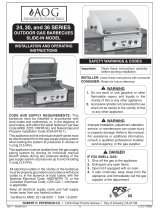
TOCONVERTAPPLIANCEFORUSEWITHPROPANEGAS
NaturalGasToPropaneGas(LP)ConversionInstructions
Models-JGD8130&JGD8345Series _-- (_)
Manifold-PropaneGas pressurerequired-10"W.C.
IncomingPropane Gas pressure requiredto appliance
pressureregulator- 11"-12"W.C.APPUANCEPRESSUR
PropaneGas conversionorificehoodsaresuppliedwith
thesemodels.
PropaneGas input specified-JGD8130/JGD8345 - E
33,000 BTU/hr /51,000 BTU/hr.
JGD8345(Shown)
INCHES
BURNER BTU/hr ORIFICE DIAMETER COLOR
Left Rear (LR) 7,500 #66 .0330 Zinc
Left Front (LF) 7,500 #66 .0330 Zinc
RightRear (RR) 9,000 #63 .0310 Blue -
Right Front (RF) 9,000 #63 .0370 Blue.---
Center Rear (CR) 9,000 #63 .0370 Blue
Center Front (CF) 9,000 #63.0370 Blue
6

TOCONVERTAPPLIANCEFORUSEWITHNATURALGAS
PropaneGas(LP)ToNaturalGas Models-JGD8130&JGD8345Series
ConversionInstructions Manifold -NaturalGas pressurerequired- 5"W.C,
If thisappliancehasbeen convertedfor usewithLP Gas, Incoming Natural Gaspressurerequiredtoappliance
each ofthefollowingmodificationsmustbeperformedto pressureregulator- 6"- 7"W.C.
converttheunitbackto NaturalGas. NaturalGas inputspecified,ModelJGD8130/JGD8345 -
36,000 BTU/hr/56,000 BTU/hr.
A. Replaceallorificehoods- Performsteps1through4on
page4. Locatethe(4)fouror(2)twoNaturalGas hoods
(with small numbers stamped on their sides) saved
from theoriginalNaturalGas unit.Page 4 Illustration
"E". The twohoodswith.0520 (#55 orifice)stampedon
themarefortheleftfrontand leftrearburners.Thetwo
hoodswiththe.0550(#54 orifice)stampedonthemare
forthetwo rightburners.
To makethese conversionadjustmentsfollow the
inatructions and illustrations ("A"through "E") pages
3 and 4,
B.Invert cap in appliancepressureregulator (see
Illustration"D"). With theapplianceinstalled, the
appliancepressureregulatoris locatedon the center
underside of theapplianceat theinlet to thegas
manifold. Identify thetypeof appliancepressure
regulatoron theunitand followthe instructionsinthe
appropriateillustration.
C. Adjust lowflame settingfor each burner. Followthe
instructionsforburnerlowflameadjustmenton page4
to increasethe simmerflamesize.
!
JGD834S (Shown)
REGULATOR
TIEDOWN
BOLTON
EACHEND
CONTAINER BLOWERCANBE
SWIVELED900
INCHES .:"
BURNER BTU/hr ORIFICE DIAMETER COLOR ....-
Left Rear (LR) 8,000#55 .0520 Brass '_'_'
Left Front(LF)8,000 #55.0520 Brass"....... -._
RightRear (RR) 10,000 #54 .0550 Brass 'i
RightFront(RF) 10,000 #54 .0550 Brass : _!::
Center Rear (CR) 10,000 #54 .0550 Brass
Center Front (CF) 10,000 #54 .0550 Brass
7_2

REQUIREDADJUSTMENTSATTIMEOFINSTALLATION
The installation ofthis appliance mustconformwithlocalcodes,or intheabsenceoflocalcodes,with
thelatesteditionoftheNationalFuelGasCodeANSIZ223.1USAorcurrentCAN/CGA-B149Installation
Code.
I_-'1 ThisrangewasmanufacturedforusewithNaturalGas.IfLPgasisthefuelofchoice,followtheconversion
to LPprocedurefoundinthe installationinstructions.
'-'-]Test allexternalconnectionsfor gasleaks.Nevertestforgasleakswithanopenflame.
I----I Testallelectricalconnections.
r-"-IAdjustallairshuttersfor properflame.
r---]Adjustallvalvesforlowflamesettings.
[_ Testtheventilationsystemforproperinstallation.
Ifa problemexistswiththedowndraftsystem,checkthe ductinginstallationto makesureit conformstotheJenn-Airspecifications.Mostdowndraftsystemproblemsareattributedto poorductingpractices.
F-"IContactyourinstalleriftheventilationsystemwillnotremovesmokeorcookingfumesfromwelltrimmedcutsof meat.
IfventilationproblemspersistcontactyourauthorizedJenn-AirServiceContractor. - :._,_-
WJENN-AIR
'I0SWESTFOURTHSTREET,NORTH" NEWTON,IA502_
/