Page is loading ...


MFJ-8504 Dual Antenna Quad Receiver Multicoupler
Features:
ɀ Flat gain, less than 3dB variation 300 kHz to 850 MHz
ɀ Low-noise high dynamic range push-pull amplifier
ɀ 30-35 dBm output TOI typical
ɀ Up to two input ports and four output ports
ɀ Input ports can be split by frequency range using optional dual internal filters.
ɀ Optional band reject, band pass, low pass, or high pass filters available
ɀ BNC inputs, SMA outputs standard
ɀ 9-15 volt dc at 150 mA nominal supply voltage
ɀ Internal unused port termination standard
ɀ Rugged construction
ɀ Fully shielded enclosure
ɀ Reverse polarity power supply protected with internal fuse
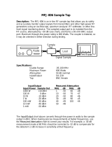
The MFJ-8504 is an amplified, single or dual input, one to four output, broadband receiver multicoupler.
This broadband coupler has excellent performance over a very wide frequency range, from below 300
kHz to above 500 MHz.
This is a low-noise gain-neutral device. It employs modern low noise push-pull high intercept MMIC
devices, carefully selected for optimal performance. Output IP3 is typically 30-35 dBm.
Overload in any system like this is a function of the total power applied to the input from multiple signals,
or the composite input power. Undesired signals still use up part of the amplifier headroom. If too much
headroom is taken up by undesired signals, multiple signals will mix and generate new phantom signals.
This unit has provisions to add optional internal plug-in filters to reduce or remove unwanted or
problematic frequency ranges.
While this unit is generally as safe as any SDR receiver, it is best to keep receive antenna(s) well away
from any active transmitting antennas.

Quick Start
1. Connect your receiver(s) to the output ports, antenna(s) to the antenna ports.
Note: Unless optional band splitting filters are installed and internal input jumpers are
reconfigured, antenna port 1 is the only active input port. Receiver port 1 is the primary active
output port. Receivers connected to ports 2-4 will function, but it is best to remove the appropriate
black jumper shunt terminating ports 2-4 when using a port.
2. Connect a 12Vdc nominal voltage, 150 mA or higher power source to the right rear standard
power connector. The plug must be center pin positive. Use a good well-filtered supply.
Connectors
The MFJ-8504 has two standard BNC input connectors. It is best to keep the receive antenna(s) well
away from any transmitting antennas. This unit is generally as safe as any SDR receiver.
The maximum safe net power applied to these terminals is 20 dBm or 3.2 volts peak. With filters safe
level fully outside filter pass band can be up to 15 volts RMS (36 dBm).
The MFJ-8504S has four standard SMA output connectors. The MFJ-8504B has four standard BNC
output connectors. For best performance unused outputs should be terminated with 50-75 ohm
terminations. Terminations are built in to the units.
Provisions have been made for the following. (These features require purchase of additional high pass
and low pass filters).
Frequency split to dual inputs this feature allows separate low band / high band antennas. Any filter
can be used separately on any antenna input port. Filters can also be connected in parallel or in series
from a single port. We currently have an 8-pole broadcast band reject, 1.7 MHz 5-pole High Pass, and 30
MHz Low Pass and High Pass 5-pole filters. The filters can be set up in multiple ways for specific needs.
The user must calculate the values and make his own non-standard filters.
ɀ Band Pass 10-pole filters allow selection of a favorite pass band of limited bandwidth such as
broadcast or a particular Ham band.
ɀ Band-reject 8-pole filters reject an undesired frequency range such as the AM broadcast band.
ɀ Low Pass 5-pole filter passes all frequencies above a cut off limit.
ɀ High Pass 5-pole filter passes all frequencies below cut off limit.
ɀ Low Pass and High Pass can be used in tandem to form a wide Band Pass or wide band reject of
almost any width. For example a 1.7MHz High Pass can be used in series with a 30MHz Low
Pass to form a 1.7-30MHz Band Pass. A 1.7MHz Low Pass is in parallel with a 30 MHz High
Pass forms a 1.7-30 MHz band reject.
This unit allows any configuration of up to two filters.
Typical Configuration
Connect a 9-15 Vdc, 150 mA or higher power source to the right rear 2.1 mm 12V connector. The plug
must be center pin positive, negative to the outer shell. Be sure the power source is relatively clean of
hum and high frequency noises. While the power jack is noise filtered and decoupled, some power
supplies can introduce noise or repeating birdies. This is especially true if your antenna system and cable
wiring has poor common mode current isolation.
In rare cases isolating the power supply from other devices, such as using a dedicated higher-quality
linear (non-switch mode) wall supply, might be necessary.
Receiver 1 is the priority receiver output. This should be the first receiver port connected. This unit is
shipped with additional Receiver ports terminated in 50 ohms internally. If additional Receiver ports are
used, they can be added in any order.

When activating any Receiver port other than port 1, it is best to disable the internal termination for that
port. Removing the cover, you will find a conventional black jumper or “shunt” located near receiver
output ports 2 through 4. Removing the shunt for a port fully enables the port. For storage, the shunt can
be left hanging on one pin. The other pin must be left open to disable the port’s termination load. It does
not matter which of the two pins are left open. If you are not using a port, it is generally best to terminate
the port. See figure 1.
We suggest adding a second receiver on port 3 or 4 first, rather than port 2. This will increase the
isolation between receivers and lessen any effects of receiver mismatches or spurious signals. Receivers
sharing ports 1 and 2 and receivers sharing ports 3 and 4 have the least isolation.
Antenna connections are dependent on station antennas. When configured with optional band separation
or splitting filters, Antenna 2 port should be set as the VHF frequency port.
General Overview
All printed circuit antenna connector positions can fit either a BNC or SMA connector. The antenna input
jacks run to a series of jumpers allowing filters to be inserted either in series or parallel, with split inputs or
a single input. This allows you to use one antenna for all bands, separate antennas sorted by frequency
using optional filters, or no filters at all.
This goes into the input of a push-pull MMIC amplifier stage with approximately 10 dB gain and 43 dBm
output IP3. Push-pull cancels even order harmonic distortion products, and the use of two MMIC’s
greatly increases dynamic range. The final output IP3, after splitting to 4 ports, is around 35 dBm IP3.
Be aware that all signals amplified by the MMIC’s will combine to “use up” available MMIC power. Many
weaker signals can be just as bad as a few strong signals at using up the dynamic range. As the
amplifiers come close to power saturation, they become increasingly non-linear and start to act like
mixers. This can cause signals to combine, and make phantom signals appear. The only solution to this
problem is to reduce the input signal level for some or all signals. The ideal input level is one where
external antenna noise sets the system noise floor. It does no good at all to have signal levels from an
antenna beyond the point where external noise just sets the receiver noise floor.
If the receiver is ideal in gain and sensitivity, without any antenna connected, you should just perceptibly
hear the background noise hiss change turning the MFJ-8504 off and on. Receiver sensitivity beyond this
point will decrease dynamic range.
The amplifiers are powered through a voltage regulator. The voltage regulator makes this device less
sensitive to power supply voltage variations, and that includes hum and noise. Additional bypassing and
filtering also helps clean up the power supply. The only significant worries are use of an unfiltered supply,
voltages below 9 volts or above 15 volts, reversed voltage, or radio frequency noises from switching type
supplies. Because this is a series linear regulator stepping down in voltage, current is constant. Less
voltage is less wasted energy.
The amplifier output is split in a traditional magic-T splitter, each split going to a second magic T. The
second magic T’s, each fed by one branch of the first split, go to receiver ports 1 and 2 from one branch
and ports 3 and 4 from the other branch. This means highest receiver isolation, of approximately 15 dB, is
between groups 1 or 2 and the group of 3 or 4, since two splitters isolate those groups.
These magic T’s have to be properly terminated for maximum isolation. To do this, 50 ohm internal
resistors are connected by removable jumpers to receiver ports 2, 3, and 4. It is not absolutely necessary
to properly terminate, but it helps performance a small amount. Whether the change is important or not
depends on each particular installation, there is no set rule. In general though, it is best to remove the
shunt when a receiver is used on ports 2-4 and to re-install it if the port is not externally loaded. It is not,
however, absolutely necessary to move the jumper unless peak performance is critical.

Figure 1
Filter Installation
Filter Jumpers
Antenna Jumper Settings
Function
Antenna
Port
HD1 HD2 HD3 HD4 HD5
No Filter 1 YES YES NO NO 1 TO 4
FL 1 ONLY 1 NO NO NO 2 TO 3 NO
FL 2 ONLY 1 YES NO 1 TO 2 NO NO
FL 2 ONLY 2 NO NO 2 TO 3 NO NO
FL1 AND 2
FL 1 - 1
FL 2 - 2
NO NO 2 TO 3 2 TO 3 NO
FL 1 AND 2 IN
SERIES
1 NO YES 1 TO 2 1 TO 2 NO
FL1 AND 2 IN
PARALLEL
1 YES NO 1 TO 2 2 TO 3 NO
Termination Jumpers
Filter Jumpers

The filters are plugged into FL1, FL2, or both depending on the filtering desired. The orientation of the
filters is not critical and can be placed in either direction. If no filters are used then only ANTENNA 1
is available for input.
Place the filters in the MFJ-8504 and set the jumpers according to the Filter Jumper chart to properly
connect the filters up.
Filter Usage
No Filter
This is the default setting where all signals presented to the ANTENNA 1 port are distributed to the
Receiver ports.
One Filter
A single filter can be installed in either FL1 or FL2 for any of the filtering functions such as the
Broadcast Band Notch filter to remove AM Broadcast band signals to eliminate overload from local
stations. The 1.7MHz High Pass filter can be used for the same thing if signals below the AM BCB
are not monitored. The 30MHz Low Pass filter is used for reducing unwanted TV, FM, and Paging
interference. The 30MHz High Pass filter is used to remove HF signals that can overload the
Multicoupler if HF monitoring is not desired.
Two Separate Filters
Two filters can be installed and by setting the jumpers for FL1 and 2 the two inputs can be used for
two different frequency ranges. The filter outputs will be connected together to feed the amplifier
stage. For example setting the 30MHz Low Pass filter in FL1 and the 30MHz High Pass filter in FL2
an HF antenna can be connected to ANTENNA 1 and a VHF antenna on ANTENNA 2.
Two Filters in Series
Two filters can be set in series to tailor the desired pass band. For example a Low Pass and a High
Pass filter can be placed in series to either pass a specific frequency range or block a specific
frequency range. To pass a single band such as 20 meters a custom High Pass filter set to 13.5Mhz
and a custom Low Pass filter set to 15MHz can be made and used to pass between 13.5 and 15MHz.
Similarly if a band needs to be reduced such as the FM Broadcast band then a Low Pass filter below
the rejected range around 87MHz and a High Pass filter above the rejected range around 109MHz in
series will reduce the FM signals.
Two Filters in Parallel
Two filters can also be placed in parallel to tailor the desired pass band. For example a custom Band
Pass filter can be made to pass a specific range of frequencies and a High Pass filter above the Band
Pass filter to pass everything above the High Pass filter cutoff.
Optional filters are available.
MFJ-8504-NC 8-pole Standard Broadcast Band reject filter.
MFJ-8504-HP 5-pole 1.7 MHz High Pass.
MFJ-8504-HP 5-pole 30 MHz High Pass.
MFJ-8504-LP 5-pole 30 MHz Low Pass.
MFJ-8504-BP 10-pole Custom Band Pass Filter. This filter is a board without inductors or capacitors
for setting up custom band pass ranges.

Schematics
MFJ-8504 Main Board
High Pass Filter Low Pass Filter
Notch Filter Band Pass Filter

Filter Board Standard Values
862-8504-HP
30MHz High Pass
QTY
Part VALUE PN Desc
2 C1, C3 56pF 220-0056 CAPACITOR, MULTILAYER, .1, 50V, 5%, NPO,
56 PF
1 C2 33pF 220-0033 CAPACITOR, MULTILAYER CER., NPO, 5%, 50
V, 33 PF
2 L1, L2 0.27uH 401-2270 INDUCTOR, MOLDED, .3~, 10%, 0.27UH
2 J1, J2 5 PIN SOCKET 612-3105 CONNECTOR, SOCKET, FEMALE, 5 POS, 8504
1 PCB 862-8504-HP
862-8504-HP
1.7MHz High Pass
QTY Part VALUE PN Desc
2 C1, C3 1000pF 220-1100 CAPACITOR, MULTILAYER, .1, 50V, 10%, X7R,
.001 UF
1 C2 680pF 220-0680 CAPACITOR, MULTILAYER, .1, 50V, 5%, NPO,
680 PF
2 L1, L2 3.9uH 401-3390 INDUCTOR, MOLDED, .3~, 10 %, ORG-WHT-
GLD, 3.9 UH
2 J1, J2 5 PIN SOCKET 612-3105 CONNECTOR, SOCKET, FEMALE, 5 POS, 8504
1 PCB 862-8504-HP
862-8504-LP
30MHz Low Pass
QTY Part VALUE PN Desc
2 C1, C2 100pF 220-0100 CAPACITOR, MULTILAYER. .1, 50V, 5%, NPO,
100 PF
2 L1, L3 0.47uH 401-2470 INDUCTOR, MOLDED, .3~, 10 %, YEL-VIO-
SLVR,0.47 UH
1 L2 0.82uH 401-2820 INDUCTOR, MOLDED, .3~, 10 %, .82 UH
2 J1, J2 5 PIN SOCKET 612-3105 CONNECTOR, SOCKET, FEMALE, 5 POS, 8504
1 PCB 862-8504-LP
862-8504-NC
BCB Notch
QTY Part VALUE PN Desc
2 C1, C3 1000pF 220-1100 CAPACITOR, MULTILAYER, .1, 50V, 10%, X7R,
.001 UF
1 C2 680pF 220-0680 CAPACITOR, MULTILAYER, .1, 50V, 5%, NPO,
680 PF
1 C4 8200pF 220-1820 CAPACITOR, MULITILAYER, .1,50V, 10%, NPO,
.0082 UF
2 L1, L2 3.3uH 401-3330 INDUCTOR, MOLDED, .3~, 10 %, ORG-ORG-
GLD, 3.3 UH
2 L3, L4 27uH 401-4270 INDUCTOR, MOLDED, .3~, 10 %, RED-VIO-BLK,
27 UH
1 L5 100uH 401-5100 INDUCTOR, MOLDED, .3~, 10 %, BRN-BLK-
BRN, 100 UH
2 J1, J2 5 PIN SOCKET 612-3105 CONNECTOR, SOCKET, FEMALE, 5 POS, 8504
1 PCB PCB 862-8504-NC

Band Pass Filter
The MFJ-8504-BP is a blank board for use by the customer to produce custom band pass filters such as
a single Ham Band to limit out of band signals and possible overload. The board consists of a 5-pole low
pass filter to set the upper limit of signals and a 5-pole high pass filter to set the lower limit of signals.
Programs such as Elsie from Tonne Software (www.tonnesoftware.com) or other on line sources make
calculating the filter values easy. Verification of the filter can be plotted through spice programs such as
LT Spice (https://www.analog.com/en/design-center/design-tools-and-calculators/ltspice-simulator.html).
The inductors used are approximately the size of 1/4W resistors and are available from multiple sources.
These should be 5% tolerance.
The capacitors used should be 5% NPO or COG type capacitors for minimum drift and with a lead
spacing around 0.1 or 0.2 inch. Voltage is not critical.
Suggested parts values for individual Amateur Bands:
Low Pass
High Pass
BAND Freq LP L1 C1 L2 C2 L3 FREQ HP C3 L4 C4 L5 C5
160 2 6.8uH 2000pF 10uH 2000pF 6.8uH 1.75 1100pF 3.6uH 750pF 3.6uH 1100pF
80 4.5 3.3uH 1000pF 4.7uH 1000pF 3.3uH 3 560pF 2uH 390pF 2uH 560pF
60 5.8 2.4uH 680pF 3.6uH 680pF 2.4uH 5 360pF 1.3uH 240pF 1.3uH 360pF
40 7.7 1.8uH 510pF 2.7uH 510pF 1.8uH 6.5 300pF 1uH 220pF 1uH 300pF
30 10.7 1.3uH 360pF 1.8uH 360pF 1.3uH 9.5 200pF 0.68uH 130pF 0.68uH 200pF
20 15 0.91uH 240pF 1.3uH 240pF 0.91uH 13 150pF 0.51uH 100pF 0.51uH 150pF
17 19 0.75uH 200pF 1.1uH 200pF 0.75uH 17 110pF 0.39uH 75pF 0.39uH 110pF
15 22.5 0.62uH 180pF 0.91uH 180pF 0.62uH 20 91pF 0.33uH 62pF 0.33uH 91pF
12 26 0.51uH 150pF 0.75uH 150pF 0.51uH 24 75pF 0.27uH 51pF 0.27uH 75pF
10 31 0.43uH 130pF 0.68uH 130pF 0.43uH 27 68pF 0.24uH 47pF 0.24uH 68pF
6 57 0.24uH 68pF 0.36uH 68pF 0.24uH 48 39pF 0.13uH 27pF 0.13uH 39pF

NOTES

FULL 12-MONTH WARRANTY
MFJ Enterprises, Inc. warrants to the original owner of this product, if manufactured by MFJ
Enterprises, Inc. and purchased from an authorized dealer or directly from MFJ Enterprises, Inc. to be
free from defects in material and workmanship for a period of 12 months from date of purchase
provided the following terms of this warranty are satisfied.
1. The purchaser must retain the dated proof-of-purchase (bill of sale, canceled check, credit card or
money order receipt, etc.) describing the product to establish the validity of the warranty claim and submit
the original or machine reproduction of such proof of purchase to MFJ Enterprises, Inc. at the time of
warranty service. MFJ Enterprises, Inc. shall have the discretion to deny warranty without dated proof-of-
purchase. Any evidence of alteration, erasure, of forgery shall be cause to void any and all warranty terms
immediately.
2. MFJ Enterprises, Inc. agrees to repair or replace at MFJ's option without charge to the original
owner any defective product provided the product is returned postage prepaid to MFJ Enterprises, Inc. with
a personal check, cashiers check, or money order. This is good on all products except antennas and software
to cover postage and handling for return from in warranty service. We also take MasterCard, Visa,
American Express, and Discover credit cards. Postage and handling may vary according to the weight of the
product in question. You should specify what type of delivery service you wish. We can send by UPS, U.S.
Postal service or Fedex. MFJ doesn’t guarantee delivery by US Postal Service.
3. MFJ Enterprises, Inc. will supply replacement parts free of charge for any MFJ product under
warranty upon request, provided the following terms are satisfied. MFJ must receive the original parts you
wish to replace, your proof-of-purchase, and a personal check, cashiers check or money order must be
provided to cover postage and handling. Postage and handling may vary according to the weight of the
product in question. We also take MasterCard, Visa, American Express and Discover credit cards.
4. This warranty is NOT void for owners who attempt to repair defective units. Technical
consultation is available by calling (662) 323-5869.
5. This warranty does not apply to kits sold by or manufactured by MFJ Enterprises, Inc.
6. Wired and tested PC board products are covered by this warranty provided only the wired and
tested PC board product is returned. Wired and tested PC boards installed in the owner's cabinet or
connected to switches, jacks, or cables, etc. sent to MFJ Enterprises, Inc. will be returned at the owner's
expense un-repaired.
7. Under no circumstances is MFJ Enterprises, Inc. liable for consequential damages to person or
property by the use of any MFJ products.
8. Out-of-Warranty Service: MFJ Enterprises, Inc. will repair any out-of-warranty product
provided the unit is shipped prepaid. All repaired units will be shipped COD to the owner. Repair charges
will be added to the COD fee unless other arrangements are made.
9. This warranty is given in lieu of any other warranty expressed or implied.
10. MFJ Enterprises, Inc. reserves the right to make changes or improvements in design or
manufacture without incurring any obligation to install such changes upon any of the products previously
manufactured.
11. All MFJ products to be serviced in-warranty or out-of-warranty should be addressed to MFJ
Enterprises, Inc., 300 Industrial Park Rd, Starkville, Mississippi 39759, USA and must be accompanied
by a letter describing the problem in detail along with a copy of your dated proof-of-purchase and a
telephone number.
12. This warranty gives you specific rights, and you may also have other rights, which vary from state
to state.

/