Chamberlain Elite RSW12VH Installation guide
- Category
- Gate Opener
- Type
- Installation guide

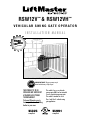
RSW12V
™
&
RSW12VH
™
VEHICULAR SWING GATE OPERATOR
I N S T A L L A T I O N M A N U A L
SOLAR
CAPABLE
SEE ACCESSORIES.
SOLAR
CAPABLE
UL325
compliant
UL991
compliant
This model is for use on vehicular
passage gates ONLY and not intended
for use on pedestrian passage gates.
This model is intended for use in
Class I and Class II vehicular swing
gate applications.
Your model may look different than the model illustrated in this manual.
IMPORTANT NOTE: The gate operation may be
limited until the battery is fully charged.
STOP
THIS PRODUCT IS TO BE
INSTALLED AND SERVICED BY
A TRAINED GATE SYSTEMS
TECHNICIAN ONLY.
Visit www.liftmaster.com to
locate a professional installing
dealer in your area.

1
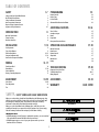
TABLE OF CONTENTS
SAFETY 1-7
Safety Symbol and Signal Word Review 1
UL325 Model Classifications 2
Safety Installation Information 3
Gate Construction Information 4
Required Safety Protection Devices 5
Important Safety Information 6-7
INTRODUCTION 8
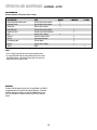
Operator Specifications 8
Carton Inventory 8
Hardware Inventory 8
INSTALLATION 9-14
Site Preparation 9
Types of Installations 9
Standard Installation 10-11
Compact Installation Only 12-13
Standard and Compact Installation 14
WIRING 14-17
Earth Ground Rod 14
Power Wiring 15-16
Connect Batteries 16
Primary/Secondary Operators 17
ADJUSTMENT 18-23
Learn Limits 18-22
Force Adjustment 23
Test 23
PROGRAMMING 24
Remote Controls 24
Keyless Entry 24
Erase All Codes 24
Alternate Radio Receiver Installation 24
ADDITIONAL FEATURES 25-26
Timer-To-Close 25
Auto Open Jumper 25
Heater 25
Party Mode 25
Entrapment Protection Devices 26
OPERATION AND MAINTENANCE 27-28
Manual Disconnect 27
Reset Button 27
Remote Control 27
Sleep Mode 27
Maintenance 28
Battery 28
TROUBLESHOOTING 29-30
Diagnostic Error Codes Chart 29
Troubleshooting Chart 30-31
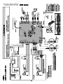
Wiring Diagram 32
ACCESSORIES 33-34
WARRANTY BACK COVER
MECHANICAL
ELECTRICAL
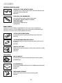
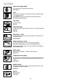
SAFETY » SAFETY SYMBOL AND SIGNAL WORD REVIEW
When you see these Safety Symbols and Signal Words on the following pages, they
will alert you to the possibility of serious injury or death if you do not comply with
the warnings that accompany them. The hazard may come from something
mechanical or from electric shock. Read the warnings carefully.
When you see this Signal Word on the following pages, it will alert you to the
possibility of damage to your gate and/or the gate operator if you do not comply
with the cautionary statements that accompany it. Read them carefully.
IMPORTANT NOTE
• BEFORE attempting to install, operate or maintain the operator, you must read and
fully understand this manual and follow all safety instructions.
• DO NOT attempt repair or service of your gate operator unless you are an
Authorized Service Technician.

2
CLASS I – RESIDENTIAL VEHICULAR
GATE OPERATOR
A vehicular gate operator (or system) intended for use in a home of one-to four
single family dwellings, or a garage or parking area associated therewith.
CLASS II – COMMERCIAL/GENERAL ACCESS
VEHICULAR GATE OPERATOR
A vehicular gate operator (or system) intended for use in a commercial location or
building such as a multi-family housing unit (five or more single family units) hotel,
garage, retail store or other building servicing the general public.
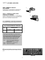
UL325 ENTRAPMENT PROTECTION REQUIREMENTS
This chart illustrates the entrapment protection requirements for the UL325 classes.
I
II
SAFETY » UL325 MODEL CLASSIFICATIONS
NOTE: UL requires that all installations must have warning signs placed in plain
view on both sides of the gate to warn pedestrians of the dangers of motorized gate
systems.
GATE OPERATOR ENTRAPMENT PROTECTION
CLASS I CLASS II B1 or B2
A
UL325
Classification Secondary Type
Swing Gate Operator
In order to complete a proper installation you must satisfy the entrapment
protection chart shown. That means that the installation must have one primary
means of entrapment protection and one independent secondary means of
entrapment protection. Both primary and secondary entrapment protection
methods must be designed, arranged or configured to protect against
entrapments in both the open and close directions of gate travel.
• Type A - Inherent (built into the operator) entrapment sensing
and at least one of the following as your secondary
entrapment protection:
• Type B1 - Non-contact sensors such as photoelectric sensors,
• Type B2 - Contact sensors such as gate edges
Primary Type

3
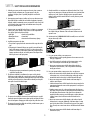
SAFETY » SAFETY INSTALLATION INFORMATION
1. Vehicular gate systems provide convenience and security. Gate systems are
comprised of many component parts. The gate operator is only one
component. Each gate system is specifically designed for an individual
application.
2. Gate operating system designers, installers and users must take into account
the possible hazards associated with each individual application. Improperly
designed, installed or maintained systems can create risks for the user as well
as the bystander. Gate systems design and installation must reduce public
exposure to potential hazards.
3. A gate operator can create high levels of force in its function as a component
part of a gate system. Therefore, safety features must be incorporated into
every design. Specific safety features include:
• Gate Edges • Guards for Exposed Rollers
• Photoelectric Sensors • Screen Mesh
• Vertical Posts • Instructional and Precautionary Signage
4. Install the gate operator only when:
a. The operator is appropriate for the construction and the usage class of the
gate.
b. All openings of a horizontal slide gate are guarded or screened from the
bottom of the gate to a minimum of 4 feet (1.2 m) above the ground to
prevent a 2-1/4 inches (6 cm) diameter sphere from passing through the
openings anywhere in the gate, and in that portion of the adjacent fence
that the gate covers in the open position.
c. All exposed pinch points are eliminated or guarded, and guarding is
supplied for exposed rollers.
5. The operator is intended for installation only on gates used for vehicles.
Pedestrians must be supplied with a separate access opening. The pedestrian
access opening shall be designed to promote pedestrian usage. Locate the gate
such that persons will not come in contact with the vehicular gate during the
entire path of travel of the vehicular gate.
6. The gate must be installed in a location so that enough clearance is supplied
between the gate and adjacent structures when opening and closing to reduce
the risk of entrapment. Swinging gates shall not open into public access areas.
7. The gate must be properly installed and work freely in both directions prior to
the installation of the gate operator.
8. Controls intended for user activation must be located at least 6 feet (1.8 m)
away from any moving part of the gate and where the user is prevented from
reaching over, under, around or through the gate to operate the controls.
Outdoor or easily accessible controls shall have a security feature to prevent
unauthorized use.
9. The Stop and/or Reset (if provided separately) must be located in the
line-of-sight of the gate. Activation of the reset control shall not cause the
operator to start.
10. A minimum of two (2) WARNING SIGNS shall be installed, one on each side of
the gate where easily visible.
11. For a gate operator utilizing a non-contact sensor:
a. Reference owner’s manual regarding placement of non-contact sensor for
each type of application.
b. Care shall be exercised to reduce the risk of nuisance tripping, such as
when a vehicle trips the sensor while the gate is still moving.
c. One or more non-contact sensors shall be located where the risk of
entrapment or obstruction exists, such as the perimeter reachable by a
moving gate or barrier.
12. For a gate operator utilizing a contact sensor such as an edge sensor:
a. One or more contact sensors shall be located where the risk of entrapment
or obstruction exists, such as at the leading edge, trailing edge and post
mounted both inside and outside of a vehicular horizontal slide gate.
b. One or more contact sensors shall be located at the bottom edge of a
vehicular vertical lift gate.
c. A hard wired contact sensor shall be located and its wiring arranged so the
communication between the sensor and the gate operator is not subject to
mechanical damage.
d. A wireless contact sensor such as the one that transmits radio frequency
(RF) signals to the gate operator for entrapment protection functions shall
be located where the transmission of the signals are not obstructed or
impeded by building structures, natural landscaping or similar obstruction.
A wireless contact sensor shall function under the intended end-use
conditions.
e. One or more contact sensors shall be located on the inside and outside
leading edge of a swing gate. Additionally, if the bottom edge of a swing
gate is greater than 6 inches (152 mm) above the ground at any point in
its arc of travel, one or more contact sensors shall be located on the bottom
edge.
f. One or more contact sensors shall be located at the bottom edge of a
vertical barrier (arm).

4
SAFETY » GATE CONSTRUCTION INFORMATION
1.1 Gates shall be constructed in accordance with the provisions given for the
appropriate gate type listed, refer to ASTM F2200 for additional gate types.
1.2 Gates shall be designed, constructed and installed to not fall over more than
45 degrees from the vertical plane, when a gate is detached from the
supporting hardware.
1.3 Gates shall have smooth bottom edges, with vertical bottom edged
protrusions not exceeding 0.50 inches (12.7 mm) when other than the
exceptions listed in ASTM F2200.
1.4 The minimum height for barbed tape shall not be less than 8 feet (2.44 m)
above grade and for barbed wire shall not be less than 6 feet (1.83 m)
above grade.
1.5 An existing gate latch shall be disabled when a manually operated gate is
retrofitted with a powered gate operator.
1.6 A gate latch shall not be installed on an automatically operated gate.
1.7 Protrusions shall not be permitted on any gate, refer to ASTM F2200 for
Exceptions.
1.8 Gates shall be designed, constructed and installed such that their movement
shall not be initiated by gravity when an automatic operator is disconnected.
1.9 A pedestrian gate shall not be incorporated into a vehicular gate panel or
that portion of the adjacent fence that the gate covers in the open position.
1. GENERAL REQUIREMENTS
2. SPECIFIC APPLICATIONS
2.1 Any non-automated gate that is to be automated shall be upgraded to
conform to the provisions of this specification.
2.2 This specification shall not apply to gates generally used for pedestrian
access and to vehicular gates not to be automated.
2.3 Any existing automated gate, when the operator requires replacement, shall
be upgraded to conform to the provisions of this specification in effect at
that time.
3. VEHICULAR HORIZONTAL SLIDE GATES
3.1 The following provisions shall apply to Class I, Class II and Class III vehicular
horizontal slide gates:
3.1.1 All weight bearing exposed rollers 8 feet (2.44 m), or less, above grade
shall be guarded or covered.
3.1.2 All openings located between 48 inches (1.22 m) and 72 inches (1.83 m)
above grade shall be designed, guarded or screened to prevent a 4 inch
(102 mm) diameter sphere from passing through the openings anywhere in
the gate, and in that portion of the adjacent fence that covers in the open
position.
3.1.3 A gap, measured in the horizontal plane parallel to the roadway, between a
fixed stationary object nearest the roadway, (such as a gate support post)
and the gate frame when the gate is in either the fully open position or the
fully closed position, shall not exceed 2 1/4 inches (57 mm), refer to ASTM
F2200 for Exception.
3.1.4 Positive stops shall be required to limit travel to the designed fully open and
fully closed positions. These stops shall be installed at either the top of the
gate, or at the bottom of the gate where such stops shall horizontally or
vertically project no more than is required to perform their intended
function.
3.1.5 All gates shall be designed with sufficient lateral stability to assure that the
gate will enter a receiver guide, refer to ASTM F2200 for panel types.
3.2 The following provisions shall apply to Class IV vehicular horizontal slide
gates:
3.2.1 All weight bearing exposed rollers 8 feet (2.44 m), or less, above grade
shall be guarded or covered.
3.2.2 Positive stops shall be required to limit travel to the designed fully open and
fully closed positions. These stops shall be installed at either the top of the
gate, or at the bottom of the gate where such stops shall horizontally or
vertically project no more than is required to perform their intended
function.
4. VEHICULAR HORIZONTAL SWING GATES
4.1 The following provisions shall apply to Class 1, Class II and Class III vehicular
horizontal swing gates:
4.1.1 Gates shall be designed, constructed and installed so as not to create an
entrapment area between the gate and the supporting structure or other
fixed object when the gate moves toward the fully open position, subject to
the provisions in the 4.1.1.1 and 4.1.1.2.
4.1.1.1 The width of an object (such as a wall, pillar or column) covered by a swing
gate when in the open position shall not exceed 4 inches (102 mm),
measured from the centerline of the pivot point of the gate, refer to ASTM
F2200 for exception.
4.1.1.2 Except for the zone specified in Section 4.1.1.1, the distance between a
fixed object such as a wall, pillar or column, and a swing gate when in the
open position shall not be less than 16 inches (406 mm), refer to ASTM
F2200 for exception.
4.2 Class IV vehicular horizontal swing gates shall be designed, constructed and
installed in accordance with security related parameters specific to the
application in question.
Vehicular gates should be installed in accordance with ASTM F2200: Standard Specification for Automated Vehicular Gate Construction. For a copy, contact ASTM directly at
610-832-9585 or www.astm.org.

5
Outside Safety
Loop
Center
Loop
Inside Safety
Loop
Outside Property
Inside Property
Center
Loop
Entrapment
Danger
To prevent SERIOUS INJURY or DEATH from a moving gate:
• Entrapment protection devices MUST be installed to protect anyone who may
come near a moving gate.
• Locate entrapment protection devices to protect in BOTH the open and close gate
cycles.
• Locate entrapment protection devices to protect between moving gate and RIGID
objects, such as posts or walls.
SAFETY » REQUIRED SAFETY PROTECTION DEVICES
Edge sensor
for close cycle
Edge sensor for open cycle
Install photoelectric sensors and edge sensors to protect against any entrapment or
safety conditions encountered in your gate application.
The safety loops allow the gate to stay open when vehicles are obstructing the gate
path. Suggested for vehicles 14 feet (4.27 m) or longer. Safety loops are not
required safety devices but are recommended.
NON-CONTACT SENSORS
Use photoelectric sensor model 50-220.
CONTACT SENSORS (EDGE SENSORS)
Use edge sensor models G65MG0204, G65MG0205, G65MGR205, or G65MGS205
(2-wire, non-monitored).
Center Loop
Inside Safety
Loop
Inside Property
Outside Safety
Loop
Outside Property
Safety Danger
nter Loop
Safety Danger
Center
C
C
Entrapment
Danger
Entrapment
Danger
Outside Safety
Loop
Center
Loop
Inside Safety
Loop
Outside Property
Inside Property
Outsid
Center
Loop
Entrapment
Danger

6
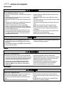
SAFETY » IMPORTANT SAFETY INFORMATION
INSTALLATION
To prevent SERIOUS INJURY or DEATH from a moving gate:
• Pinch points must be guarded at all times. Install enclosed-style gate tracks and
roller guards.
• Place screen mesh 4 feet (1.2 m) high on the gate to prevent access through
openings anywhere the gate may travel.
• Mount controls at least 6 feet (1.8 m) from the gate or ANY moving part of the
gate.
• Install Warning signs on EACH side of gate in PLAIN VIEW. Permanently secure
each Warning sign in a suitable manner using fastening holes.
• This operator is intended for vehicular use only. To prevent INJURY to
pedestrians, a separate pedestrian access should be supplied, visible from the
gate. Locate the pedestrian access where there is not a chance of INJURY at any
point during full movement of the gate.
• Contact sensors MUST be located at the leading and trailing edges, and post
mounted both inside and outside a horizontal slide gate. Non-contact sensors
such as photo eyes MUST be mounted across the gate opening and operate
during BOTH the open and close cycles.
• Entrapment protection devices MUST be installed to protect anyone who may
come near a moving gate.
• Locate entrapment protection devices to protect in BOTH the open and close
gate cycles.
• Locate entrapment protection devices to protect between moving gate and RIGID
objects, such as posts or walls.
• Too much force on gate will interfere with proper operation of safety reversal
system.
• NEVER increase force beyond minimum amount required to close gate.
• NEVER use force adjustments to compensate for a binding or sticking gate.
• If one control (force or travel limits) is adjusted, the other control may also
need adjustment.
• After ANY adjustments are made, the safety reversal system MUST be tested.
Gate MUST reverse on contact with a rigid object.
• DO NOT touch the heater when switch is on, heater may be hot.
• To AVOID damaging gas, power or other underground utility lines, contact
underground utility locating companies BEFORE digging more than 18 inches
(46 cm) deep.
• To prevent damage to the operator or gate, DO NOT drive the limit actuators on
the shaft past their normal positions.
• ALWAYS wear protective gloves and eye protection when changing the battery
or working around the battery compartment.
To reduce the risk of SEVERE INJURY or DEATH:
• ANY maintenance to the operator or in the area near the operator MUST NOT
be performed until disconnecting the electrical power and locking-out the power
via the operator power switch. Upon completion of maintenance the area MUST
be cleared and secured, at that time the unit may be returned to service.
• Disconnect power at the fuse box BEFORE proceeding. Operator MUST be
properly grounded and connected in accordance with national and local
electrical codes. NOTE: The operator should be on a separate fused line of
adequate capacity.
• ALL electrical connections MUST be made by a qualified individual.
• DO NOT install ANY wiring or attempt to run the operator without consulting the
wiring diagram. We recommend that you install an optional reversing edge
BEFORE proceeding with the control station installation.
• ALL power wiring should be on a dedicated circuit and well protected. The
location of the power disconnect should be visible and clearly labeled.
• ALL power and control wiring MUST be run in separate conduit.
WIRING
To reduce the risk of SEVERE INJURY or DEATH:
• Without a properly installed safety reversal system, persons (particularly small
children) could be SERIOUSLY INJURED or KILLED by a moving gate.
• Too much force on gate will interfere with proper operation of safety reversal
system.
• NEVER increase force beyond minimum amount required to close gate.
• NEVER use force adjustments to compensate for a binding or sticking gate.
• If one control (force or travel limits) is adjusted, the other control may also need
adjustment.
• After ANY adjustments are made, the safety reversal system MUST be tested.
Gate MUST reverse on contact with a rigid object.
ADJUSTMENT

7
To prevent SERIOUS INJURY or DEATH from a moving gate:
• Entrapment protection devices MUST be installed to protect anyone who may
come near a moving gate.
• Locate entrapment protection devices to protect in BOTH the open and close gate
cycles.
• Locate entrapment protection devices to protect between moving gate and RIGID
objects, such as posts or walls.
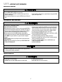
ADDITIONAL FEATURES
To reduce the risk of SEVERE INJURY or DEATH:
• READ AND FOLLOW ALL INSTRUCTIONS.
• ANY maintenance to the operator or in the area near the operator MUST NOT be
performed until disconnecting the electrical power and locking-out the power via
the operator power switch. Upon completion of maintenance the area MUST be
cleared and secured, at that time the unit may be returned to service.
• Disconnect power at the fuse box BEFORE proceeding. Operator MUST be
properly grounded and connected in accordance with national and local electrical
codes. NOTE: The operator should be on a separate fused line of adequate
capacity.
• NEVER let children operate or play with gate controls. Keep the remote control
away from children.
• ALWAYS keep people and objects away from the gate. NO ONE SHOULD CROSS
THE PATH OF THE MOVING GATE.
• Test the gate operator monthly. The gate MUST reverse on contact with a rigid
object or stop when an object activates the non-contact sensors. After adjusting
the force or the limit of travel, retest the gate operator. Failure to adjust and
retest the gate operator properly can increase the risk of INJURY or DEATH.
• Use the emergency release ONLY when the gate is not moving.
• KEEP GATES PROPERLY MAINTAINED. Read the owner’s manual. Have a qualified
service person make repairs to gate hardware.
• ALL maintenance MUST be performed by a LiftMaster professional.
• Activate gate or door ONLY when it can be seen clearly, is properly adjusted and
there are no obstructions to door travel.
• To reduce the risk of FIRE or INJURY to persons use ONLY LiftMaster part
29-NP712 for replacement batteries.
• SAVE THESE INSTRUCTIONS.
MAINTENANCE AND OPERATION
To protect against fire and electrocution:
• DISCONNECT power and battery BEFORE installing or servicing operator.
For continued protection against fire:
• Replace ONLY with fuse of same type and rating.
TROUBLESHOOTING
SAFETY » IMPORTANT SAFETY INFORMATION
• ALWAYS wear protective gloves and eye protection when changing the battery
or working around the battery compartment.

8
INTRODUCTION » OPERATOR SPECIFICATIONS + CARTON INVENTORY + HARDWARE INVENTORY
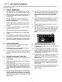
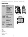
OPERATOR SPECIFICATIONS
This model is intended for use in vehicular swing gate applications:
Gate Classifications: CLASS I & II
Main Supply (Motor): 12 Vdc
Accessory Power: 12 V nominal Class II battery
voltage source is limited to:
• Solar or AC Cable up to
50 feet - 500 mA
• AC Cable 50 feet up to
250 feet - 250 mA
• AC Cable 250 feet up to
1000 feet - 100 mA
NOTE: Increased accessory power drawn from
the operator will shorten the battery life.
Current Consumption: 5 Amps at 120 Vac
Battery Charger Supply: 13.5 Vac, 30 Va, Direct Plug in
Power Supply, Class II Compliant
Heater Draw (Optional): 325 watts
Main AC Supply: 120 Vac
DC Absorbed Power: 2 Amps
Solar Power Max: 12 V at 30 watts max.
Maximum Gate
Weight/Length: 400 lbs. / 16 ft. long
600 lbs. / 12 ft. long
700 lbs. / 10 ft. long
800 lbs. / 8 ft. long
1000 lbs. / 6 ft. long
Daily Cycle Rate using
transformer power: 250 cycles/day
Maximum Gate
Travel Range: 115 degrees
Temperature: -20°C to 40°C (-4°F to 104°F)
without Heater
-40°C to 40°C (-40°F to 104°F)
with Heater
Control Board Fuse: 30 Amp (2)
CARTON INVENTORY
• Operator
• Operator arm assembly
• Transformer
• Documentation Packet
• Battery 12 Vdc 7AH (1)
• Keys (2)
HARDWARE INVENTORY
• Warning Signs (2)
• Warranty Card
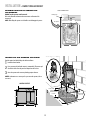
SIDE VIEW FRONT VIEW
13.6"
27.66"
17"
MOUNTING FOOTPRINT
14"
12.2" 13.6"
17"

9
INSTALLATION » SITE PREPARATION + TYPES OF INSTALLATIONS
SITE PREPARATION
BEFORE installing the operator, be sure to check the following:
• Gate is constructed and installed according to ASTM F2200 standards
• Gate fits specifications of operator
• National and local building codes
• Earth ground rod
• UL approved conduit for low and high voltage
• Mounting considerations post or pad
• Operator placement
SAFETY CONSIDERATIONS:
• Warning signs
• Entrapment devices such as loops, contact sensors and non-contact sensors
STANDARD INSTALLATION
The illustration is an example of a standard installation.
Outside Safety
Loop
Center
Loop
Inside Safety
Loop
Outside Property
Inside Property
Outsid
Center
Loop
Entrapment
Danger
COMPACT INSTALLATION
The illustration is an example of a compact installation. If the operator arm will hit
an obstruction when the gate is in the open position follow the directions for Compact
Installation (pages 12-14).
TYPES OF INSTALLATIONS
IMPORTANT: There are many factors to consider when installing this gate operator, such as gate size and site layout. The following instructions and illustrations should be
used as a general guide so please note that your installation may be different.

10
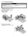
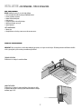
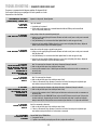
INSTALLATION » STANDARD INSTALLATION
CONCRETE PAD AND OPERATOR ATTACHMENT
4 Concrete Anchors
1/2" x 3 1/2"
6" Above Ground
MOUNTING FOOTPRINT
14"
12.2" 13.6"
17"
30" Below Ground
Concrete Pad
28"
24"
Post
25"
10"
Concrete Pad
Short Arm
29.5"
35.5"
Long Arm
14"
2"
24"
28"
26"
Hinge Center
OUT
IN
SAMPLE STANDARD INSTALLATION
NOTE: An alternative
to a concrete pad is to
post mount the
operator (refer to
accessories).

11
1
2
3
4
5
6
34.5"
44"
44"
45"
44.75"
41"
34.75"
36.5"
37"
37"
35.75"
39"
29.5"
32.5"
30.5"
30.5"
29.5"
27.5"
35"
42"
40"
37"
32"
28.5"
14"
14"
14"
14"
14"
14"
43"
32"
40"
43"
44"
41"
ABCDE
1
2
3
4
5
6
46"
46.75"
46.75"
47.25"
47"
42.5"
35.5"
35.5"
37"
37.25"
35"
33"
29.5"
33.5"
31.5"
30"
29.5"
26.5"
35"
42"
40"
37"
32"
28.5"
11"
11"
11"
11"
11"
11"
45"
37"
41"
45"
45"
41"
ABCDE
DISTANCE
DISTANCE
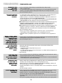
INSTALLATION » STANDARD INSTALLATION
Dimension (A) thru (E) are from the center of one pivot point to the center of another pivot point.
PROCEED TO PAGE 14.
POSITION THE GATE BRACKET
Gate Hinge Center
A
B
C
E
OUT
IN
Short Arm
Long Arm
Concrete Pad
OUT
IN
DD MINUS 10"
10"
Wall
DISTANCE
If this dimension is
between 20 and 32
inches, a compact
installation is necessary.
Refer to following page.
SAMPLE STANDARD INSTALLATION IS SHOWN ON PREVIOUS PAGE.
Caution: If the gate is longer than 18 feet, follow CHART A: A-2.
Suggestion: The dimensions between the gate and the concrete pad is always 10 inches less than the dimension D.
Example: D = 42", if the dimensions between the gate and the concrete pad is 32".
CHART A CHART B

12
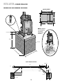
INSTALLATION » COMPACT INSTALLATION ONLY
DETERMINE LOCATION FOR CONCRETE PAD
AND OPERATOR
DO NOT run the operator until instructed.
Refer to the illustration to determine the measurements and location of the
concrete pad.
NOTE: When lifting the operator use the handle to avoid damaging the operator. 26-1/2"
9"
Output Shaft Center
28"
24"
Gate Hinge Center
TOP VIEW OF OPERATOR AND GATE
Gate Open 90°
CONCRETE PAD AND OPERATOR ATTACHMENT
Check the national and local building codes before installation.
Install the electrical conduit.
Pour a concrete pad (reinforced concrete is recommended). The concrete pad
should be 6 inches above the ground and deeper than the frost line.
Secure the operator to the concrete pad with appropriate fasteners.
NOTE: An alternative to a concrete pad is to post mount the operator (refer to
accessories).
1
2
3
4 Concrete Anchors
1/2" x 3 1/2"
6" Above Ground
28"
24"
13
2Below the frost line.
Check all national and
local codes.
14"
12.2" 13.6"
17"
MOUNTING FOOTPRINT

13
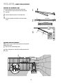
INSTALLATION » COMPACT INSTALLATION ONLY
SHORTEN THE OPERATOR ARM
For a compact installation the operator arm will have to be shortened.
Take the operator arm apart and remove the inner sleeves from the
outer tubing.
Cut the outer tubing of the operator arm to the lengths shown.
Put the arm back together and adjust the arm to the measurements
as shown.
1
2
3
1
2
3
CUT LONG ARM SECTION
SHORT ARM SECTION
CUT
CUT
10" 22" 4"
20"4"
23"
25-1/2"
POSITION THE GATE BRACKET
NOTE:
It may be necessary to attach horizontal reinforcement to the gate before
attaching the gate bracket.
Measure 33 inches from the gate hinge center.
Make sure the operator arm is level and tack weld the gate bracket in this
position.
1
2
Tack weld
Gate Hinge Center
33"
1
2

14
INSTALLATION » STANDARD INSTALLATION + COMPACT INSTALLATION
WELD THE OPERATOR ARM
Once the operator arm measurements are verified:
Weld the gate bracket to the gate.
Weld the short arm section.
Weld the long arm section.
NOTE:
Completely weld around the outer tubing and bracket.
1
2
3
1
2
3
SECURE THE OPERATOR ARM TO THE
OUTPUT SHAFT
Position the operator arm onto the output shaft so that the pin slides into
the slot.
Adjust the nuts on the operator arm so the operator arm fits snug on the
output shaft yet still allows enough room to swivel (the handle must be in a
90° position).
Tighten the handle by pushing it down. Test to make sure the operator arm
does not slip on the output shaft.
1
2
3
12
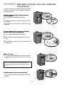
WIRING » EARTH GROUND ROD
EARTH GROUND ROD
Proper grounding gives an electrical charge, such as from an electrical static
discharge or a near lightning strike, a path from which to dissipate its energy safely
into the earth. Without this path, the intense energy generated by lightning could be
directed towards the gate operator. Although nothing can absorb the tremendous
power of a direct lightning strike, proper grounding can protect the gate operator in
most cases.
Use the proper earth ground rod for your local area. The ground wire must be a
single, whole piece of wire. Never splice two wires for the ground wire. If you should
cut the ground wire too short, break it, or destroy its integrity, replace it with a
single wire length. NOTE: If the operator is not grounded properly the range of the
remote controls will be reduced.
Install the earth ground rod within 3 feet of the operator.
Attach the ground wire to the ground terminal on the control board.
1
2
OVLD
AC PWR
/SOLAR
Check national and local
codes for proper depth
12 gauge copper
wire
1
2
3
Output
Shaft
Slot
Pin

15
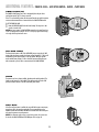
WIRING » POWER WIRING
POWER WIRING
This operator can be powered by the internal receptacle, an external
receptacle or a solar panel (not provided).
INTERNAL RECEPTACLE
NOTE:
All power wiring should be on a dedicated circuit,
calculated using NEC
guidelines. National and local codes and conditions must be reviewed for suitability
of wire installation.
Remove the access panel.
Connect AC power to the operator:
Connect the green wire to the ground screw in the access panel.
Connect the black and white wires together with wire nuts.
HEATER WIRING:
NOTE:
If your operator comes with a heater it will have to be wired. The heater may
be wired to the internal receptacle or a separate junction box.
If wiring the heater to the internal receptacle, thread the heater wires through the
same knockout as the power wires. Connect the heater wires to the power wires with
wire nuts (green to green, black to black, and white to white).
Replace the access panel.
Connect the wires from the transformer to the AC PWR/SOLAR terminal located
on the control board.
Plug the transformer into the internal receptacle.
Wire Gauge 16 - 100 feet (30 m) Wire Gauge 10 - 1000 feet (305 m)
120 VAC POWER WIRE (STRANDED COPPER WIRE)
1
2
3
4
5
CHGR
OVLD CTRL
AC PWR
/SOLAR
1
2
3
4
5
EXTERNAL RECEPTACLE
NOTE:
All power wiring should be on a dedicated circuit,
calculated using NEC
guidelines. National and local electrical codes must be reviewed for suitability of wire
installation.
The transformer must be located in a dry location that is protected from
weather conditions, such as inside the house or garage.
Run low voltage wire between the transformer and the operator.
Connect the wires from the transformer to the AC PWR/SOLAR terminal located
on the control board.
Plug the transformer into the external receptacle.
1
2
3
CHGR
OVLD CTRL
AC PWR
/SOLAR
1
2
3
14.5
Vac COM 13.5
Vac
POWER WIRE (STRANDED COPPER WIRE)
500 feet or less 500 feet to 1000 feet
Wire Gauge 14 - 500 feet (152 m) Wire Gauge 12 - 1000 feet (305 m)
Transformer 13.5 Vac Transformer 14.5 Vac

16
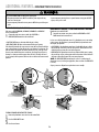
WIRING » POWER WIRING + CONNECT BATTERIES
POWER WIRING
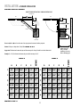
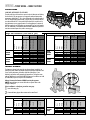
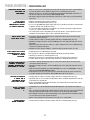
SOLAR PANEL (NOT PROVIDED. SEE ACCESSORIES.)
The solar panel(s) must be located in an open area clear of obstructions and shading
for the entire day. The gate operator is not supported in northern climates where
temperatures reach below -4˚F. This is due to cold weather and a reduced number of
hours of sunlight during the winter months. Cycle rate may vary from solar chart for
areas that reach below 32˚F. Solar panels should be cleaned on a regular basis for
best performance to ensure proper operation. For solar applications, a minimum of
20W solar panels and two 7AH batteries are recommended. For Zone 3 cold weather
sites, one 33AH battery is recommended. We recommend LiftMaster low power draw
accessories to minimize power draw, refer to accessory page.
NOT AVAILABLE
NOT AVAILABLE
11
1
2
3
3
2
CONNECT BATTERIES
The batteries are charged in the circuit by using the transformer (provided) or an
optional solar panel. Batteries will degrade over time depending on temperature and
usage. For best performance, the batteries should be replaced every 3 years.
Batteries do not perform well in extremely cold temperatures. The operator comes
with one 7AH battery. A second 7AH (29-NP712) battery may be added or one 33AH
(A12330SGLPK) may be used in place of the 7AH batteries.
Always disconnect the batteries BEFORE servicing the operator.
NOTE:
Setting the battery on concrete will not have a negative affect on the
charging or battery life.
If the installation is a dual gate, proceed to next page.
Locate the battery plug.
Connect the battery plug to either connector on the control board.
1
2
Battery
Plug
Connector
1
2
Provided
Optional
(not provided)
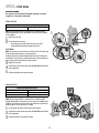
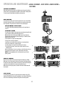
Accessories Zone 1 Zone 2 Zone 3
(6 Hrs sunlight/day) (4 Hrs Sunlight/day) (2 Hrs Sunlight/day)
20W
SOLAR
PANEL
30W
SOLAR
PANEL
50 50 38 43 20
✔ 48 50 32 36 17
✔ 50 50 30 35 12
✔ 41 49 21 26 3
✔ 1 9 0 0 0
50 50 50 50 31
✔ 50 50 48 50 26
✔ 50 50 50 50 24
✔ 50 50 41 49 15
✔ 30 43 1 9 0
NUMBER OF CYCLES PER DAY
Single Gate Installations (16 ft. 400 lb. gate)
Solenoid Lock
50 mA
100 mA
300 mA
2 7AH Batteries (optional)
1 33AH Battery (optional)
2 7AH Batteries (optional)
1 33AH Battery (optional)
1 33AH Battery (optional)
25 29 17 19 9
✔ 23 27 15 17 8
✔ 22 26 13 15 5
✔ 18 22 9 12 1
✔ 0 4 0 0 0
39 45 25 29 14
✔ 35 41 23 27 13
✔ 35 41 22 26 10
✔ 31 37 18 22 6
✔ 13 19 0 4 0
Solenoid Lock
50 mA
100 mA
300 mA
2 7AH Batteries (optional)
1 33AH Battery (optional)
2 7AH Batteries (optional)
1 33AH Battery (optional)
1 33AH Battery (optional)
20W
SOLAR
PANEL
30W
SOLAR
PANEL
Dual Gate Installations (16 ft. 400 lb. gate)
Accessories Zone 1 Zone 2 Zone 3
(6 Hrs sunlight/day) (4 Hrs Sunlight/day) (2 Hrs Sunlight/day)
Accessories Single Gate (16 ft. 400 lb. gate)
BATTERY
BACKUP
(BBU)
40 100 275
✔ 36 83 228
✔ 43 98 269
✔ 42 97 267
✔ 41 94 258
Solenoid Lock
50 mA
100 mA
300 mA
1 7AH Battery
(standard)
2 7AH Batteries
(optional)
1 33AH Battery
(optional)
Accessories Dual Gate (16 ft. 400 lb. gate)
BATTERY
BACKUP
(BBU)
19 44 121
✔ 17 40 111
✔ 19 44 121
✔ 19 43 120
✔ 19 43 118
Solenoid Lock
50 mA
100 mA
300 mA
1 7AH Battery
(standard)
2 7AH Batteries
(optional)
1 33AH Battery
(optional)
NUMBER OF CYCLES FOR BATTERY BACKUP

17
WIRING » PRIMARY / SECONDARY OPERATORS
PRIMARY/SECONDARY OPERATORS
NOTE: Use the Dual Gate Wiring Kit. Refer to the accessory page for more
information.
Before digging, contact local underground utility locating companies. Choose one
operator to be the primary and the other operator to be the secondary.
NOTES:
• The gate with the longer travel span must be set as the primary operator
(GATE 1).
• If one gate is overlapping the other (an ornamental overhang, maglock or solenoid
lock) consider which gate needs to open/close first and plan accordingly. The gate
that opens first MUST be the primary operator (GATE 1).
The control board in the secondary operator is not used.
Trench across driveway to bury the extension cable.
Disconnect the terminal block connector (with the attached label) from the end
of the extension cable. Thread the extension cable through the bottom of the
primary operator (using the watertight connectors) and reconnect the extension
cable wires to the terminal block connector.
Connect the terminal block (with the attached label) to the GATE 2 connector of
the primary operator’s control board.
Disconnect the terminal block connector from the other end of the extension
cable. Thread the extension cable through the bottom of the secondary
operator (using the watertight connectors) and reconnect the wires to the
terminal block connector.
Disconnect the wires from the GATE 1 connector on the secondary operator and
connect them to the terminal block connector.
Move the battery from the secondary operator to the primary operator.
Connect the plugs from the batteries to the connectors on the control board.
If one gate overlaps the other, set the LOCK/BIPART DELAY switch to the ON
position on the primary control board. Factory default setting is OFF.
1
2
3
GATE 2
ACCESSORY
POWER
GATE 1
GR
WH
YL
BL
RD
BR
GR
WH
YL
BL
RD
BR
12 V
LOCK /
ON OFF
BIPART DELAY
6
7
Battery from secondary operator
Battery from primary operator
PRIMARY OPERATOR
GATE 2
ACCESSORY
POWER
GATE 1
GR
WH
YL
BL
RD
BR
GR
WH
YL
BL
RD
BR
12 V
GATE 2
GR
WH
YL
BL
RD
BR
Extension Cable
2
1
3
PRIMARY OPERATOR SECONDARY OPERATOR
SECONDARY
CONTROL
BOARD NOT
USED
Terminal Block Connector
Red Red
Blue Blue
Green Green
Brown
Brown
White
Yellow Yellow
White
5
4Extension
Cable
Gate 1
Secondary
Operator
3
Gate 2
Label
Extension Cable
4
5
6
7

18
ADJUSTMENT » LEARN LIMITS
To reduce the risk of SEVERE INJURY or DEATH:
• Without a properly installed safety reversal system, persons (particularly small
children) could be SERIOUSLY INJURED or KILLED by a moving gate.
• Too much force on gate will interfere with proper operation of safety reversal
system.
• NEVER increase force beyond minimum amount required to close gate.
• NEVER use force adjustments to compensate for a binding or sticking gate.
• If one control (force or travel limits) is adjusted, the other control may also need
adjustment.
• After ANY adjustments are made, the safety reversal system MUST be tested.
Gate MUST reverse on contact with a rigid object.
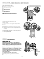
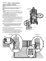
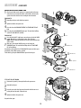
LEARN LIMIT INTRODUCTION
The limits are internal settings that indicate when the gate is in the fully open
position and the fully closed position. For proper functionality, the limits must be
programmed during the installation process.
The programming uses a combination of buttons on the control board. The specific
buttons used for programming depends on which side of the gate the primary
operator is installed and how many operators the installation includes.
BEFORE BEGINNING:
Make sure the operator arm is properly seated on the output shaft (the pin
must fit into the slot).
Make sure the handle is released on the operator arm and the gate is closed.
Make sure the learn limit cam is touching the learn limit switch.
If a mistake is made during programming:
Press the RESET button on the operator to start over.
The programming times-out automatically after 60 seconds of inactivity.
1
GATE 2
SET
OPEN
LIMIT
SET
CLOSE
LIMIT
LEARN
LIMITS
GATE 1
1
Learn Limit Cam
Handle
Learn Limit Switch
1
2
3
Slot
Pin
1
2
3

19
ADJUSTMENT » LEARN LIMITS
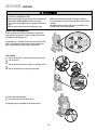
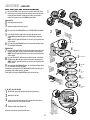
SINGLE GATE LEFT-HAND SIDE
Close the gate. Make sure the operator arm is properly seated on the output
shaft (the pin must fit into the slot). Make sure the handle is released on the
operator arm and the learn limit cam is touching the learn limit switch.
PROGRAM OPEN
Manually open the gate to the desired open position.
Tighten the handle on the operator arm.
Press and release the LEARN LIMITS BUTTON. The SET OPEN LIMIT LED will
blink.
Press and release the LEARN LIMITS button again. The control board will beep
and the SET CLOSE LIMITS LED will blink.
PROGRAM CLOSE
Press and hold the GATE 1 left button to move the gate to the desired CLOSED
position. When the gate is in the desired position, release the button.
NOTE: The GATE 1 right and left buttons can be used to jog the gate back and
forth as needed.
When gate is in the desired CLOSED position, press and release the
LEARN LIMITS button. The control board will beep and the SET CLOSE LIMITS
LED will stop blinking.
Programming is now complete. If the SET OPEN LIMIT LED continues to blink, repeat
programming. If the problem continues, see below.
Test the limits by pressing the SINGLE BUTTON to open and close the gate.
1
3
4
5
Inside
Property
Inside
Property
GATE 2
SET
CLOSE
LIMIT
GATE 1
SET
CLOSE
LIMI
T
GA
T
A
SET
OPEN
LIMIT
N
N
LEARN
LIMITS
GATE 2
SET
CLOSE
LIMIT
LEARN
LIMITS
GATE 1
SET
CLOSE
LIMI
T
LEAR
N
LIMITS
GA
T
A
SET
OPEN
LIMIT
Inside
Property
SET
CLOS
DIAGNOSTIC
GATE 1
GATE 2
SET
CLOSE
LIMIT
LEARN
LIMITS
GATE 1
G
SET
CLOSE
LIMI
T
LEAR
N
LIMITS
GA
TE
A
SET
OPEN
LIMIT
LEARN LIMITS Button
1
GATE 1 Left Button
4
"BEEP"
6
"BEEP"
5LEARN LIMITS Button
LEARN LIMITS Button
3
2
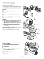
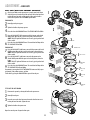
IF THE LIMITS WILL NOT PROGRAM
Disconnect the operator by releasing the handle on the operator arm.
Manually close the gate.
Loosen the screw on the learn limit cam and rotate the learn limit cam so it is
touching the learn limit switch. Tighten the screw.
Tighten the handle on the operator arm.
Program the limits again.
1
2
3
4
Learn Limit Cam
Screw
Learn Limit Switch
2
Handle
6
7
7
Page is loading ...
Page is loading ...
Page is loading ...
Page is loading ...
Page is loading ...
Page is loading ...
Page is loading ...
Page is loading ...
Page is loading ...
Page is loading ...
Page is loading ...
Page is loading ...
Page is loading ...
Page is loading ...
Page is loading ...
Page is loading ...
-
 1
1
-
 2
2
-
 3
3
-
 4
4
-
 5
5
-
 6
6
-
 7
7
-
 8
8
-
 9
9
-
 10
10
-
 11
11
-
 12
12
-
 13
13
-
 14
14
-
 15
15
-
 16
16
-
 17
17
-
 18
18
-
 19
19
-
 20
20
-
 21
21
-
 22
22
-
 23
23
-
 24
24
-
 25
25
-
 26
26
-
 27
27
-
 28
28
-
 29
29
-
 30
30
-
 31
31
-
 32
32
-
 33
33
-
 34
34
-
 35
35
-
 36
36


Chamberlain Elite RSW12VH Installation guide
- Category
- Gate Opener
- Type
- Installation guide
Ask a question and I''ll find the answer in the document
Finding information in a document is now easier with AI
Related papers
-
Chamberlain LiftMaster LA412-S Owner's manual
-
-
-
Chamberlain LiftMaster Professional SW420 Installation guide
-
-
-
-
-
-
 Elite access systems Miracle-One Owner's manual

Other documents
-
CAME BX243R Installation guide
-
-
-
-
DKS 6002 / 6003/ 6004 / 6400/ 115V Control Box Pre-2016 User manual
-
-
-
DKS 6002 Pre-2016 User manual
-
-
Nice Apollo 1650ETL Smart ETL Dual Swing Gate Operator Installation guide