9
INSTALLATION cont.
Ventilation and Clearances
Standard minimum clearance from combustible construction is as follows.
2” from side
2” from back
These griddles may be set directly, without legs, on a curbed base or non-combustible surface.
If the griddle is set without legs on a non-combustible oor or a curbed base, maintain a 4-inch
back clearance.
Do not install the griddle directly against a non-combustible back wall or surface.
Do not install the griddle closer than 12 inches from an uncontrolled heat source (char broiler etc.).
Keep the appliance area free and clear of combustible material and do not obstruct the ow of
combustion or ventilation air.
Electrical Connection
There is one power supply connection on the 2, 3, and 4-foot griddles. There are two power
supply connections on 5 and 6-foot griddles. Refer to the power supply chart in the Technical
Data portion of this manual, for proper power supply size.
There is (1) one 1 1/4-inch conduit knockout on 2, 3 and 4-foot griddles located at the rear of the
griddle, through the back and the bottom of the griddle body. There are (2) two 1 1/4-inch conduit
knockouts provided on the 5 and 6-foot griddles. Use a supply wire suitable for at least 90 degree
centigrade.
This Selectronic griddle is shipped from the factory, wired for 208/240 or 480 volts, the 208/240
griddle is a dual voltage design. Jumper wires on terminal strip next to the main power supply
connection determine the griddle voltage. For a 208-volt power supply, leave the jumpers in place.
For a 240-volt power supply disconnect the jumpers as indicated on the tag on the terminal strip.
The 480-volt griddle can be operated on 480 volts only and must be specied when ordering.
Technical Data
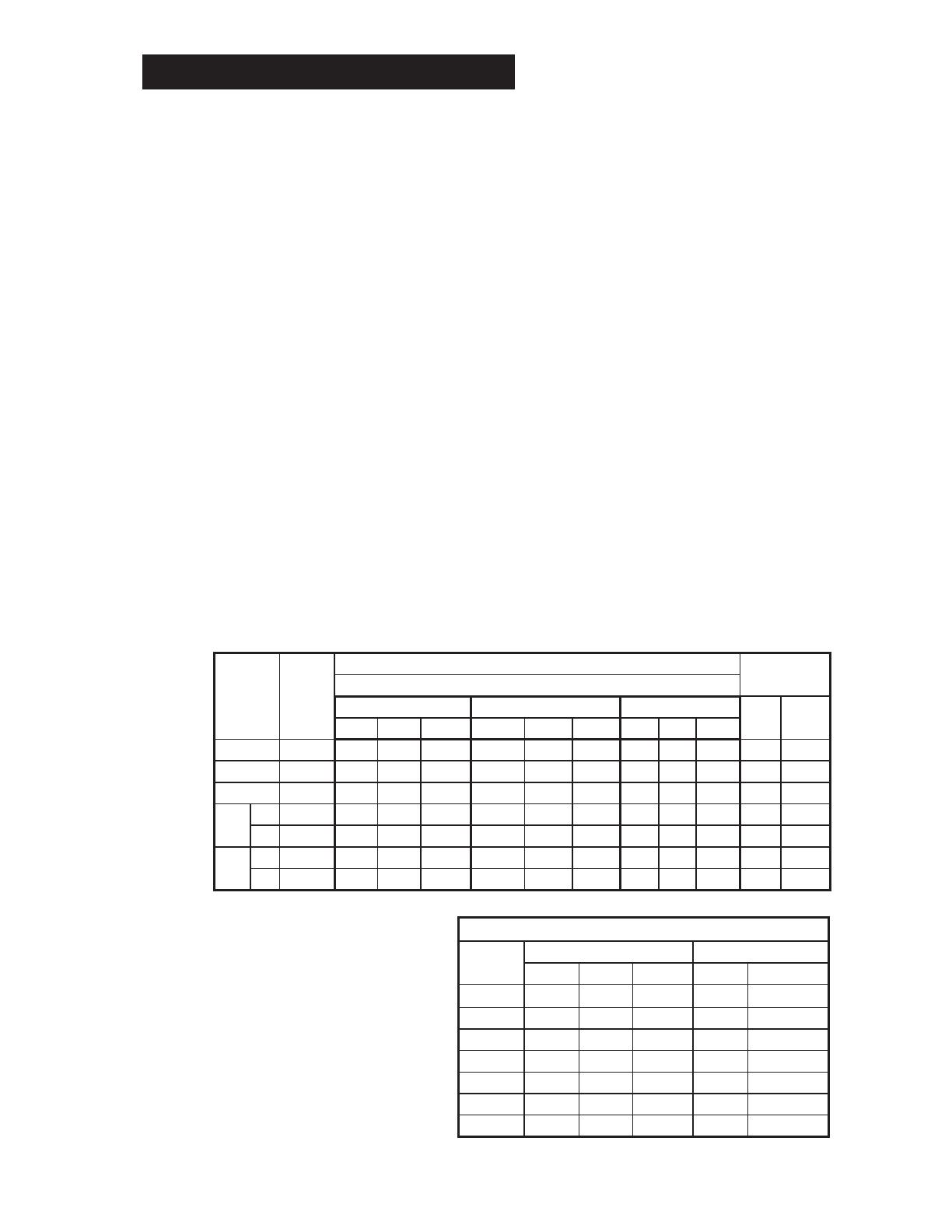
Phasing
All griddles are shipped from the
factory set up for a three-phase
service. Rearrange the wires in
the power supply terminal block to
convert the griddle to single phase.
Re-phasing the griddle is not
chargeable to Lang Manufacturing
Company as warranty. To convert
to single-phase have a Lang
Authorized Service Agent, follow
this chart.
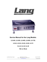
MODEL
NUMBER
TOTAL
K.W.
NOMINAL AMPS PER LINE
SINGLE PHASETHREE PHASE
208 Volt 240 Volt 480 Volt
208V 240VL1 L2 L3 L1 L2 L3 L1 L2 L3
24” 12 50 28.8 28.8 43.3 25 25 21.7 12.5 12.5 57.7 50
36” 18 50 50 50 43.3 43.3 43.3 21.7 21.7 21.7 86.5 75
48” 24 75 75 50 65 65 43.3 32.5 32.5 21.7 115.5 100
60”
#1 18 50 50 50 43.3 43.3 43.3 21.7 21.7 21.7 86.5 75
#2 12 50 28.8 28.8 43.3 25 25 21.7 12.5 12.5 57.7 50
72”
#1 18 50 50 50 43.3 43.3 43.3 21.7 21.7 21.7 86.5 75
#2 18 50 50 50 43.3 43.3 43.3 21.7 21.7 21.7 86.5 75
PHASING BY WIRE NUMBER
MODEL
NUMBER
THREE PHASE SINGLE PHASE
LINE 1 LINE 2 LINE 3 LINE 1 LINE 2
124S 1,4 2 3 1,3 2,6
136S 1,4 2,5 3,6 1,3,5 2,4,6
148S 1,4,7 2,5,8 3,6,9 1,3,5,7 2,4,6,8
160S #1 1,4 2,5 3,6 1,3,5 2,4,6
160S #2 1,4 2 3 1,3 2,6
172S #1 1,4 2,5 3,6 1,3,5 2,4,6
172S #2 1,4 2,5 3,6 1,3,5 2,4,6