ActronAir CL01-2W Installation guide

Category
Split-system air conditioners
Type
Installation guide

ActronAir CL01-2W is a wall control interface that offers convenient and user-friendly control over your ActronAir air conditioning unit. With its intuitive interface and a range of features, the CL01-2W makes it easy to manage your indoor climate and enhance your comfort.

ActronAir CL01-2W is a wall control interface that offers convenient and user-friendly control over your ActronAir air conditioning unit. With its intuitive interface and a range of features, the CL01-2W makes it easy to manage your indoor climate and enhance your comfort.

WALL CONTROL
Installation Instructions
Control Interface
Model Number
CL01-2W (White)
CL01-2G (Grey)
That’s better. That’s Actron.
AVAILABLE AS AN OPTIONAL ACCESSORY
FOR TRI-CAPACITY MODELS ONLY
IMPORTANT NOTE:
Please read this manual carefully before installing or operating your air conditioning unit.
That’s better. That’s Actron.
2Installation Guide - CL01-2 Control Interface Insert
Document: 9590-3026 Ver. 2 220907
Installation Guide CL01-2 Control Interface
Table of Contents
01. Safety Precautions ........................................................................................................................3
02. Specifications ...............................................................................................................................3
03. Installation ...................................................................................................................................3
04. Wiring Diagram ............................................................................................................................5
05. Assigning Sensor ......................................................................................................................... 6
Installation Guide CL01-2 Control Interface
3
Installation Guide - CL01-2 Control Interface Insert
Document: 9590-3026 Ver. 2 220907
01. Safety Precautions
1. Read all instructions in this manual before operating the air conditioning unit. Failure to do so may result in damage
to the unit and void your warranty.
2. Turn off the power supply to the unit and follow necessary Lock Out & Tag Out procedures to ensure that power
supply is not re-energised accidentally.
3. This control interface has power supply from ActronAir CM100 controller via screwed terminals and twisted pair data
cable. Ensure that this unit is not installed on voltages other than specified.
4. Make sure that the unit installation complies with all relevant council regulations and building code standards. All
electrical wiring must be in accordance with current electrical authority regulations and all wiring connection must
follow the electrical diagrams provided.
5. WH&S rules and regulations must be observed and will take precedence during installation process.
6. Only use this Control Interface with an ActronAir air conditioner as described in this installation guide.
02. Specifications
Voltage: 12VDC +/- 10%
Operating conditions: -10 to 60OC, < 90% RH non-condensing
Storage conditions: -20 to 70OC, < 90% RH non-condensing
Data: RS485 / 4 Core (2 Pair) Twisted Pair 7/0.20 (AWG24) Shielded Data Cable, Maximum Cable Length up to 200m
Dimensions - mm: 130 x 130 x 14.5 (W x H x D)
NOTE
Do not use ActronAir 4 Core Data Cable Part Numbers: 4070-003 / AMDC4 or Non-Twisted Pair multi core cable.
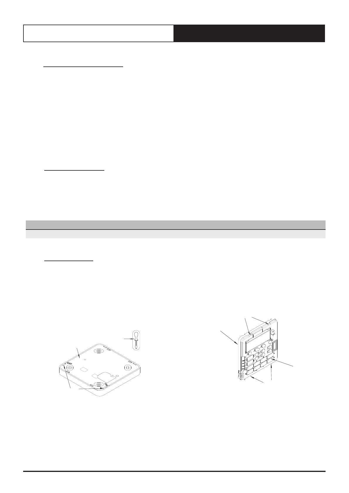
03. Installation
1. Remove front cover, as shown in the diagram below
Insert and gently twist screwdriver into the slot at the side
of the Control Interface. Do this procedure alternately
between the two slots until the front of the control
separates from the back cover.
Use large enough flat blade screwdriver to fit into the slot
in order to avoid damaging the Control Interface.
INSERT
SCREWDRIVER
AND TWIST
CONTROL
INTERFACE
SLOTS
2. Remove back cover, as shown in the diagram below
Insert and gently twist screwdriver into the slot at the top
and the bottom of the Control Interface. Do this procedure
alternately between the four slots until the back cover of
the control separates.
Use large enough flat blade screwdriver to fit into the slot
in order to avoid damaging the Control Interface.
SLOTS
PCB CASING
BACK COVER
SLOTS
4Installation Guide - CL01-2 Control Interface Insert
Document: 9590-3026 Ver. 2 220907
Installation Guide CL01-2 Control Interface
3. Mount back cover to the wall
Mount the back cover to the wall with screws via screw
holes. If required, the use of a plasterboard mounting
bracket is recommended to mount the back cover to the
wall.
Ensure that the Control Interface back cover is aligned and
leveled on the wall before tightening the screws.
BACK COVER
PLASTERBOARD
MOUNTING BRACKET
SCREW HOLES
4. Connect wiring at the back of Control Interface
Ensure that all wiring is tightly connected. All wiring must
be in accordance with the provided wiring diagram.
5. Attach PCB casing to the back cover
Attach the PCB casing by aligning with the back cover
mounted on the wall.
Ensure the PCB casing makes a ‘click’ sound after
mounting.
BACK COVER
PCB CASING
NOTE
Front cover can be removed even after installation. Press at
the bottom of the control interface and pull the front cover.
6. Attach the front cover, as shown in the diagram below
IMPORTANT
Ensure protective film is removed from inside of the front
cover before attaching.
After attaching the front cover, check that the Control
Interface is aligned and leveled on the wall.
BACK COVER
AS MOUNTED
ON THE WALL
FRONT COVER
PROG
EXIT
REPEAT
CLO1-2W
HRS
DISPAFTER
MODE
FAN
RESTORE
CANCEL
NFC
POWER
485 A
485 B
GND
DO NOT CONNECT TRACE WIRE
TO CONTROL INTERFACE.
CUT WIRE, AS SHORT AS POSSIBLE,
IN ORDER TO PREVENT SHORTING.
TWISTED PAIR - 2
TWISTED PAIR - 1
Installation Guide CL01-2 Control Interface
5
Installation Guide - CL01-2 Control Interface Insert
Document: 9590-3026 Ver. 2 220907
04. Wiring Diagram
CM100 TRI-CAPACITY CONTROL SYSTEM WIRING DIAGRAM
WITH CL01 WALL CONTROLLER
CAY470-700T
PKY470-960T
LEGEND
I/F
WC-1
TERM
OCB
IFB
R
This drawing remains the intellectual property of Actron Engineering
Pty Ltd. Reproduction, modification and/or distribution are prohibited
without written consent.
Revision
Description:
B
9525-4903
Rev.
B
Description
INCLUDED INDOOR UNIT
Date
30-03-2016
By
RL
PCR
2671
ORIGINAL
A4
Size:
Base
Model No:
Variation:
Variation Code:
A
Drawing No:
Drawn: Date: 01-04-2015
MH
Approved: MJH Date: 30-03-2016
6Q2-3Q2
CM100 CONTROLS WITH
CL01 WALL CONTROLLER
OCB
485A
POWER
WC-1
TWISTED PAIR 1: DATA
485A TO R+/T+ TERMINAL
485B TO R-/T- TERMINAL
TWISTED PAIR 2: POWER
POWER TO Vout TERMINAL
GND TO GND TERMINAL
NOTE:
DO NOT CONNECT
SCREEN WIRE AT
WALL CONTROL
DATA CABLE:
4 CORE (2 PAIR) TWISTED PAIR
7/0.20 (AWG24) MINIMUM
SHIELDED DATA CABLE
INSTALLER TO PROVIDE
ACTRONAIR FACTORY
SUPPLIED & FITTED
I/F
FIELD WIRING BY INSTALLER -
CABLE MUST BE 2 CORE 7/0.30
SHIELDED TWISTED PAIR DATA CABLE
WITH SCREEN WIRE CONNECTED TO
J9FBUS1 "GND" TERMINAL ON OCB
TWISTED PAIR 1: DATA
485A TO R+/T+ TERMINAL
485B TO R-/T- TERMINAL
N
A
240V AC
POWER IN
COM 10V 10V ACOMDI1 0V 0V BNC
FAULT
INPUT
0-10V
IN
0-10V
OUT
485
OUTDOOR
AUX
OUTPUT
AUX
SENSOR
COIL
SENSOR
13
12
NO
PWM2 PWM 1
1144
FAN POWER 1
240V AC
FAN POWER 2
240V AC
AA
NN
OFF
ON
DIP SWITCH
1234
AC250VAC/10A FUSE1
GLASS FUSE
250V AC 10 A
SLOW BLOW
SIZE 5 x 20mm
IFB
INDOOR UNIT
FOR CAY470-700T ONLY
CL01 IS CONNECTED
TO THE J9FBUS1
TERMINALS ON OCB
6Installation Guide - CL01-2 Control Interface Insert
Document: 9590-3026 Ver. 2 220907
Installation Guide CL01-2 Control Interface
Important Notes for Return Air Temperature Sensor
SPLIT DUCTED UNITS (CAY/EVY or ELY)
Leave the factory fitted Return Air Temperature Sensor in place. If disconnected, a fault will be registered and
displayed in the screen. See the Split System Installation Guide, Air Temperature Setup for more details.
PACKAGE UNITS (PKY)
You must connect the factory supplied Return Air Temperature Sensor. If not connected, a fault will be registered and
displayed in the screen. Please refer to wiring diagram provided with your unit. See the Split System Installation Guide,
Air Temperature Setup for more details.
Follow the steps for assigning sensors, below, for the weighting of influence for both the return air temperature
sensor and the built-in CL01-2 sensor. Note that the Control Interface displays shown below are for Split Ducted Units,
these are for illustration purposes only. Displays for Package Units are without Use INDOOR sensor parameter.
05. Assigning Sensor
The CL01-2 Control Interface built-in sensor can be use to read your room temperature in combination with the return air
temperature sensor. This can be assigned via Service menu, as follows:
Service Menu f. Service settings c. Thermoregulation Thermoregulation 02
Display Progression:
G. Service
F. Alarm History
Main Menu G
H. Manufacturer
Service menu Gf
d. Working log
f. Service settings
e. Communicate cong.
Service menu Gfc
a. Working hour set
c. Thermoregulation
b. Probe adjustment
Thermoregulation Gfc2
Room Temperature
Use INDOOR sensor
After Hours SW & Temp
Probe weight value 0
Room Temp. 18.0oc
Wall Cont Temp. 26.8oc
Control Value 18.0oc
G. Service f. Service settings c. Thermoregulation Thermoregulation 02
NOTE
Thermoregulation is under Service settings sub-level menu and password protected, enter the Service Password (7378) in
order to access this sub-menu.
From Thermoregulation 02 sub-level menu, you have the option to use 0% up to 100% CL01-2 sensor reading as follows:
**Default setting
Probe weight value CL01-2
Sensor Reading
Room Air Temp
Sensor Reading
Example Display *
(CP05 / CP10)
0 ** 0% 100%
Thermoregulation Gfc2
Room Temperature
Use INDOOR sensor
After Hours SW & Temp
Probe weight value 0
Room Temp. 18.0oc
Wall Cont Temp. 26.8oc
Control Value 18.0oc
40 40% 60%
Thermoregulation Gfc2
Room Temperature
Use INDOOR sensor
After Hours SW & Temp
Probe weight value 40
Room Temp. 18.0oc
Wall Cont Temp. 26.8oc
Control Value 18.0oc
50 50% 50%
Thermoregulation Gfc2
Room Temperature
Use INDOOR sensor
After Hours SW & Temp
Probe weight value 50
Room Temp. 18.0oc
Wall Cont Temp. 26.8oc
Control Value 18.0oc
100 100% 0%
Thermoregulation Gfc2
Room Temperature
Use INDOOR sensor
After Hours SW & Temp
Probe weight value 100
Room Temp. 18.0oc
Wall Cont Temp. 26.8oc
Control Value 18.0oc
* Legend:
Room Temp. = Return Air Temp Sensor Reading
Wall Cont Temp. = CL01-2 Built -In Sensor Reading
Installation Guide CL01-2 Control Interface
7
Installation Guide - CL01-2 Control Interface Insert
Document: 9590-3026 Ver. 2 220907
NOTE
The Control Value is determined by the following example:
Control Value calculation at Probe weight value of 50% :
Control Value = 50% Room Temp + 50% Wall Cont Temp
= (0.5 x 18.0) + (0.5 x 26.8)
= 9.0 + 13.4
= 22.4OC (Displayed on CL01-2 as INSIDE temperature when button is pressed)
Important Note For Split Ducted Tri-Capacity Models:
By default, the Return Air Temperature Sensor is connected to the Indoor Board. As an option, this can be wired to
the Outdoor Board which will require changing the sensor setting from INDOOR sensor to OUTDOOR sensor via
Thermoregulation Gfc2, as shown on the right.
Change setting from
INDOOR sensor to
OUTDOOR sensor
Thermoregulation Gfc2
Room Temperature
Use OUTDOOR sensor
After Hours SW & Temp
Probe weight value 50
Room Temp. 18.0oc
Wall Cont Temp. 26.8oc
Control Value 18.0oc
©Copyright 2019 Actron Engineering Pty Limited ABN 34 002767240. ®Registered Trade Marks of Actron Engineering Pty Limited.
ActronAir is constantly seeking ways to improve the design of it’s products, therefore specifications are subject to change without notice.
Document: 9590-3026 Ver. 2 Issue Date: 09/2022
  • Page 1 1
  • Page 2 2
  • Page 3 3
  • Page 4 4
  • Page 5 5
  • Page 6 6
  • Page 7 7
  • Page 8 8

ActronAir CL01-2W Installation guide

Category
Split-system air conditioners
Type
Installation guide

ActronAir CL01-2W is a wall control interface that offers convenient and user-friendly control over your ActronAir air conditioning unit. With its intuitive interface and a range of features, the CL01-2W makes it easy to manage your indoor climate and enhance your comfort.

Ask a question and I''ll find the answer in the document

Finding information in a document is now easier with AI