
Instruction Manual
зѬҕєѪѠдѥіѲнҖкѥь
D28810, D28811, D28803
Heavy Duty Small Angle Grinder
ѯзіѪѷѠкѯлѨѕіѯеҖѥєѫєѰээѲнҖкѥьўьѤд

ݏ༹ዐ࿔ 13
English 3
Thai 17

3
General Safety Rules – For All T
ools
W
ARNING! Read and understand all instructions.
Failure to follow all instructions listed below may
result in electric shock, fire and/or serious personal injury
.
SA
VE THESE INSTRUCTIONS
WORK AREA
• Keep your work area clean and well lit.
Cluttered benches
and dark areas invite accidents.
•
Do not operate power tools in explosive atmospheres, such
as in the presence of flammable liquids, gases, or dust.
Power tools create sparks which may ignite the dust or fumes.
•
Keep bystanders, children, and visitors away while operat-
ing a power tool.
Distractions can cause you to lose control.
ELECTRICAL
SAFETY
•
Grounded tools must be plugged into an outlet properly
installed and grounded in accordance with all codes and
ordinances. Never remove the grounding prong or modify
the plug in any way
. Do not use any adaptor plugs. Check
with a qualified electrician if you are in doubt as to whether
the outlet is properly grounded.
If the tools should electrical-
ly malfunction or break down, grounding provides a low resist-
ance path to carry electricity away from the user
. Applicable
only to Class I (grounded) tools.
•
Double insulated tools are equipped with a polarized plug
(one blade is wider than the other
.) This plug will fit in a
polarized outlet only one way
. If the plug does not fit fully in
the outlet, reverse the plug. If it still does not fit, contact a
qualified electrician to install a polarized outlet. Do not
change the plug in any way
.
Double insulation
eliminates
the need for the three wire grounded power cord and grounded
power supply system. Applicable only to Class II (double
insulated) tools.
•
Avoid body contact with grounded surfaces such as pipes,
radiators, ranges and refrigerators.
There is an increased risk
of electric shock if your body is grounded.
•
Don’
t expose power tools to rain or wet conditions.
Water
entering a power tool will increase the risk of electric shock.
•
Do not abuse the cord. Never use the cord to carry the tools
or pull the plug from an outlet. Keep cord away from heat,
oil, sharp edges or moving parts. Replace damaged cords
immediately
.
Damaged cords increase the risk of electric shock.
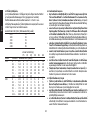
Technical data
Power input W
No Load Speed
/min
Max. Disc Diameter mm
Side handle*
Dust-ejection system
One-piece brush arm
Brushes
Flange
Spindle Thread
W
eight
kg
D28810
680
10000
100
No
No
Yes
Pop off
Anti-Lock
M10
1.80
D28811
720
10000
100
No
No
Yes
Pop off
Anti-Lock
M10
1.80
D28803
850
Rated frequency Hz
50/60
50/60
50/60
Rated voltage V
220-240~
220-240~
220-240~
10000
100
Regular
No
Yes
Pop off
Anti-Lock
M10
1.85
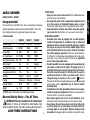
ANGLE GRINDER
Congratulation!
D28810, D28811, D28803
You have chosen a D
E
WALT tool. Years of experience, thorough
product development and innovation make D
E
WALT one of the
most reliable partners for professional power tool users.
English
*D28803 sold in China does not include side handle.

4
Using an extension cable
If an extension cable is required, use and approved extension
cable suitable for the power input of this tool (See technical data).
The minimum conductor size is 1.5 mm
2
.
When using a cable reel, always unwind the cable completely.
Also refer to the table below.
Conductor size (mm
2
) Cable rating (Amperes)
0.75
6
1.00
10
1.50
15
2.50
20
4.00 25
Cable length (m)
7.5
15 25
30
45
60
Voltage
Amperes Cable rating (Amperes)
115
0
- 2.0
6 6
6
6
6
10
2.1
-
3.4 6 6
6
6
15
15
3.5
-
5.0 6 6 10
15
20
20
5.1
-
7.0 10 10 15
20
20
25
7.1
-
12.0 15 15 20
25
25
-
12.1
-
20.0 20 20 25 - -
-
230
0
-
2.0 6 6
6
6
6
6
2.1
-
3.4 6 6
6
6
6
6
3.5
-
5.0 6 6
6
6
10
15
5.1
-
7.0 10 10 10
10
15
15
7.1
-
12.0 15 15 15
15
20
20
12.1
-
20.0 20 20 20
20
25
-
PERSONAL SAFETY
•
Stay alert, watch what you are doing and use common
sense when operating a power tool. Do not use tool while
tired or under the influence of drugs, alcohol, or medica-
tion.
A moment of inattention while operating power tools may
result in serious personal
injury
.
• Dress properly
. Do not wear loose clothing or jewelry
.
Contain long hair
. Keep your hair
, clothing, and gloves away
from moving parts. Loose clothing, jewelry
, or long hair can be
caught in moving parts.
Air vents often cover moving parts and
should also be avoided.
•
Avoid accidental starting. Be sure switch is of
f before plug-
ging in.
Carrying tools with your finger on the switch or plugging
in tools that have the switch on invites accidents.
•
Remove adjusting keys or wrenches before turning the tool
on.
A wrench or a key that is left attached to a rotating part of
the tool may result in personal injury
.
•
Do not overreach. Keep proper footing and balance at all
times.
Proper footing and balance enables better control of the
tool in unexpected situations.
•
Use safety equipment. Always wear eye protection. Dust
mask, non-skid safety shoes, hard hat, or hearing protection
must be used for appropriate conditions.
TOOL USE AND CARE
•
Use clamps or other practical way to secure and support
the workpiece to a stable platform.
Holding the work by hand
or against your body is unstable and may lead to loss of control.
• Do not force tool. Use the correct tool for your application.
The correct tool will do the job better and safer at the rate for
which it is designed.
• Do not use tool if switch does not turn it on or of
f.
Any tool
that cannot be controlled with the switch is dangerous and must
be repaired.
English

5
missing or damaged.
If grinding wheel or accessory loosens,
it may dismount from the machine and may cause serious
personal injury.
•
Always use proper guard with grinding wheel.
A
guard pro-
tects operator from broken wheel fragments and wheel contact.
• Accessories must be rated for at least the speed recom-
mended on the tool warning label. Wheels and other acces-
sories running over rated speed can fly apart and cause injury.
Accessory ratings must be above listed minimum wheel speed
as shown on tool nameplate.
•
Hold tool by insulated gripping surfaces when performing
an operation where the cutting tool may contact hidden
wiring or its own cord.
Contact with a “live” wire will make
exposed metal parts of the tool “live” and shock the operator
.
•
AL
W
AYS WEAR EYE PROTECTION WHEN USING THIS
T
OOL.
•
Use of accessories not specified in this manual is not rec-
ommended and may be hazardous.
Use of power boosters
that would cause the tool to be driven at speeds greater than its
rated speed constitutes misuse.
•
Do not use circular saw blades or any other toothed blades
with this tool.
Serious injury may result.
• When starting the tool with a new or replacement wheel, or
a new or replacement wire brush installed, hold the tool in
a well protected area and let it run for one minute.
If the
wheel has an undetected crack or flaw
, it should burst in less
than one minute. If the wire brush has loose wires, they will be
detected. Never start the tool with a person in line with the
wheel. This includes the operator
.
• Avoid bouncing the wheel or giving it rough treatment.
If this
occurs, stop the tool and inspect the wheel for cracks or flaws.
•
Disconnect the plug from the power source before making
any adjustments, changing accessories, or storing the tool.
Such preventative safety measures reduce the risk of starting
the tool accidentally.
•
Store idle tools out of reach of children and other untrained
persons.
T
ools are dangerous in the hands of untrained users.
• Maintain tools with care. Keep cutting tools sharp and
clean.
Properly maintained tools, with sharp cutting edges are
less likely to bind and are easier to control.
• Check for misalignment or binding of moving parts, break-
age of parts, and any other condition that may af
fect the
tool’
s operation. If damaged, have the tool serviced before
using. Many accidents are caused by poorly maintained tools.
•
Use only accessories that are recommended by the manu-
facturer for your model.
Accessories that may be suitable for
one tool, may become hazardous when used on another tool.
SERVICE
• Tool service must be performed only by qualified repair
personnel.
Service or maintenance performed by unqualified
personnel could result in a risk of injury.
•
When servicing a tool, use only identical replacement parts.
Follow instructions in the Maintenance section of this man-
ual.
Use of unauthorized parts or failure to follow maintenance
instructions may create a risk of electric shock or injury
.
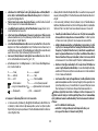
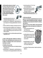
Additional Specific Safety Instructions
for Grinders
•
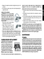
Check that the grinding wheel backing flange has a yellow
rubber ring (I) installed, see Figure 1. Replace rubber ring if
missing, damaged or worn. See page 9 for details regarding
proper accessory installation.
WARNING:
The grinding wheel or accessory may loosen
during coast-down of the tool when shut off if rubber ring is
English

6
•
When the wheel is pinched or bound tightly by the workpiece,
the wheel stalls and the motor reaction drives the unit rapidl
y
back toward or away from the operator
.
•
Kickback is the result of tool misuse and/or incorrect operating
procedures or conditions and can be avoided by taking proper
precautions as given below:
•
Maintain a firm grip with both hands on the unit and posi-
tion your body and arm to allow you to resist kickback
forces.
Kickback forces can be controlled by the operator, if
proper precautions are taken.
•
When wheel is binding, or when interrupting a cut for any
reason, release the trigger and hold the unit motionless
in the material until the wheel comes to a complete stop.
Never attempt to remove the unit from the work or pull
the unit backward while the wheel is in motion or kick-
back may occur
.
Investigate and take corrective actions to
eliminate the cause of wheel binding.
•
When restarting a cut-of
f tool in the workpiece, check
that the wheel is not engaged into the material.
If wheel is
binding, it may walk up or kickback from the workpiece as the
tool is restarted.
•
Support large panels to minimize the risk of wheel pinch-
ing and kickback.
Large panels tend to sag under their own
weight. Support must be placed under the panel on both
sides, near the line of cut and near the edge of the panel.
W
ARNING:
Some dust created by power sanding, sawing,
grinding, drilling, and other construction activities contains chem-
icals known to cause cancer
, birth defects, or other reproductive
harm. Some examples of these chemicals are:
•
lead from lead-based paints,
•
crystalline silica from bricks and cement and other masonry
products, and
•
arsenic and chromium from chemically-treated lumber (CCA).
•
Direct sparks away from operator
, bystanders or flammable
materials. Sparks may be produced while cutting and/or
grind
ing. Sparks may cause burns or start fires.
•
Always use side handle.
T
ighten the handle securely
. The
side handle should always be used to maintain control of the tool
at all times.
•
Never cut into area that may contain electrical wiring or
piping. Serious injury may result.
•
C
lean out your tool often, especially after heavy use. Dust
and grit containing metal particles often accumulate on interior
surfaces and could create an electric shock hazard.
•
Do not operate this tool for long periods of time.
V
ibration
caused by the operating action of this tool may cause permanent
injury to fingers, hands, and arms. Use gloves to provide extra
cushion, take frequent rest periods, and limit daily time of use.
• Direct the Dust Ejection System (DES) away from operator
and coworkers. Serious injury may result (Fig. 1, H).
•
The label on your tool may include the following symbols. The
symbols and their definitions are as follows:
V
..........volts
A..............amperes
Hz
........hertz
W
............watts
min ......minutes
..........alternating current
....direct current
n
o............no load speed
........Class II
Construction ..........safety alert symbol
........earthing terminal
…/min
....revolutions per minute
Causes and Operator Pr
evention
of Kickback
•
Kickback is a sudden reaction to a pinched, bound or misaligned
wheel, wire brush or flap disc causing an uncontrolled cut-off
tool to lift up and out of the workpiece toward the operator.
English

7
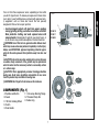
FIG. 1
Your risk from these exposures varies, depending on how often
you do this type of work. To
reduce your exposure to these chem-
icals: work in a well ventilated area, and work with approved safe-
ty equipment, such as those dust masks that are specially
designed to filter out microscopic particles.
• Avoid prolonged contact with dust from power sanding,
sawing, grinding, drilling, and other construction activities.
Wear protective clothing and wash exposed areas with
soap and water
.
Allowing dust to get into your mouth, eyes, or
lay on the skin may promote absorption of harmful chemicals.
WARNING:
Use of this tool can generate and/or disburse dust,
which may cause serious and permanent respiratory or other injury
.
Always use NIOSH/OSHA
approved respiratory protection appro-
priate for the dust exposure. Direct particles away from face and
body
.
CAUTION:
Use extra care when working into a corner because
a sudden, sharp movement of the grinder may be experienced
when the wheel or other accessory contacts a secondary surface
or a surface edge.
CAUTION: W
ear appropriate personal hearing protection
during use.
Under some conditions and duration of use, noise
from this product may contribute to hearing loss.
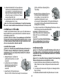
COMPONENTS (Fig. 1)
A. Spindle Lock Button
G.
Threaded Clamp Nut
F. Anti-Lockup Backing Flange
B. Guard
C.
100 mm Grinding Wheel
H. Rubber ring
D.
Switch
E.
Side Handle
WARNING:
Don’t forget to fix all screws on the enclosure.
English
G
F
D28810
D28811
D28803
H
A
C
B
D

8
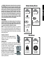
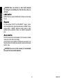
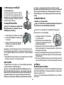
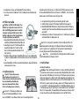
Mounting Guar
d
MOUNTING AND REMOVING GUARD
CAUTION: T
urn of
f and unplug the tool before making any
CAUTION:
adjustments or removing or installing attachments or acces-
sories.
ASSEMBL
Y AND ADJUSTMENTS
ATTACHING SIDE HANDLE
The side handle (E) can be fitted to either
side of the gear case in the threaded holes,
as shown. Before using the tool, check that
the handle is tightened securely. Use a
wrench to firmly tighten the side handle.
Rotating the Gear Case
1.
Remove guard and flanges from tool.
2.
3. Separating the gear case from motor
housing not more than 6.4mm, rotate
the gear case head to desired position.
NOTE: If the gear case and motor housing become separated by
more than 6.4mm, the tool must be serviced and re-assembled by a
D
EW
AL
T
service center
. Failure to have the tool serviced may
cause brush, motor and bearing failure.
3.
Re-install screws to attach the gear case to the motor housing.
Tighten screws to 18 in./lbs. torque. Overtightening could causescrews to strip.
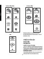
Accessories
It is important to choose the correct guards, backing pads and
flanges to use with grinder accessories.
WARNING:
90˚
90˚
E
R
emove t
h
e
fo
u
r
c
o
r
ne
r
s
c
rew
s
a
tt
a
c
h
in
g
t
h
e
g
e
a
r c
a
s
e
t
o
mo
t
o
r ho
u
s
i
n
g
.
English
Always make sure the guard is correctly fitted
before and during using the tool.
1.
Loosen screw. Align the lugs (K) on the
guard with slots (L) on the gear case.
2.
Push the guard down until the guard lug
engages and rotates freely in the groove
on the gear case hub.
3.
Rotate guard (B) into desired working position.
The guard body
should be positioned between the spindle and the operator to
provide maximum operator protection.
4.
T
ighten the screw to secure the guard on the gear case cover
.
Y
ou should be unable to rotate the guard by hand. Do not
operate grinder with a loose guard.
5.
T
o remove the guard, loosen screw
, rotate the guard so that the
arrows are aligned and pull up on the guard.
OPERA
TION
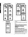
Guards and Flanges
It is important to choose the correct guards and flanges to use with
the grinder accessories. See page 6 and this page for the correct
accessories.
NOTE: Edge grinding and cutting can be performed with
T
ype 27
wheels designed and specified for this purpose.
K
L
B
CAUTION:
Turn off and unplug the
tool before making any adjustments
or removing or installing attachments
or accessories.
100mm abrasive wheels with rated max. speed lower
than 13500RPM can’t be used on this grinder. Accessories must be
rated for at least the speed recommended on the tool warning label.
Wheels and other accessories running over rated accessory speed
may burst and cause injury. Threaded accessories must have a
M10 hub. Every unthreaded accessory must have a 16mm arbor
hole. If it does not, it may have been designed for a circular saw and
should not be used. Use only the accessories shown on pages 9–10
of this manual. Accessory ratings must be above listed minimum
wheel speed as shown on tool nameplate.

9
WARNING:
English
Switches
CAUTION:
Hold the side handle and body of the tool firmly to
maintain control of the tool at start up and during use and until the
wheel or accessory stops rotating. Make sure the wheel has come
to a complete stop before laying the tool down.
NOTE: To reduce unexpected tool movement, do not switch the
tool on or off while under load conditions. Allow the grinder to run
up to full speed before touching the work surface. Lift the tool from
the surface before turning the tool off. Allow the tool to stop rotating
before putting it down.
TURN ON & TURN OFF
To turn on the tool, push the toggle switch(N) to ''1"
position, to turn off the tool, push the toggle
switch(N) to "0" position.
SPINDLE LOCK
The spindle lock (A) is provided to prevent the spindle from rotat-
ing when installing or removing wheels. Operate the spindle lock
only when the tool is turned off, unplugged
from the power supply, and has come to a
complete stop. Do not engage the spindle
lock while the tool is operating because
damage to the tool will result. To engage the
lock, depress the spindle lock button and
rotate the spindle until you are unable to
rotate the spindle further.
A
A
Type 27 guard
100mm Grinding Wheels
backing flange
threaded clamp nut
Type 27 hubbed wheel
Type 27 guard
Type 27 depressed
center wheel
Wire Wheels
75mm/100mm
wire cupbrush
75mm/100mm
wire wheel
Type 27 guard
Type 27 guard
N
100mm abrasive wheels with rated max. speed lower
than 13500RPM can’t be used on this grinder. Accessories must be
rated for at least the speed recommended on the tool warning label.
Wheels and other accessories running over rated accessory speed
may burst and cause injury. Threaded accessories must have a
M10 hub. Every unthreaded accessory must have a 16mm arbor
hole. If it does not, it may have been designed for a circular saw and
should not be used. Use only the accessories shown on pages
9–10 of this manual. Accessory ratings must be above listed
minimum wheel speed as shown on tool nameplate.

10
English
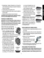
rubber backing pad
sanding disc
threaded clamp nut
Sanding Discs
100mm Cutting Wheels
Type 1 guard
backing flange
abrasive cutting wheel
clamp nut
Type 1 guard
backing flange
diamond cutting wheel
clamp nut
100mm Sanding Flap Discs
hubbed sanding
flap disc
backing flange
non-hubbed sanding
flap disc
threaded clamp nut
Type 27 guard
Type 27 guard
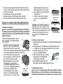
Mounting and Using Depressed Center
Grinding Wheels and Sanding
Flap Discs
MOUNTING AND REMOVING HUBBED WHEELS
CAUTION: Turn off and unplug the tool before making any
adjustments or removing or installing attachments or acces-
sories. Before reconnecting the tool, depress and release the
paddle switch to ensure that the tool is off.
Hubbed wheels install directly on the M10 threaded spindle.
Thread of accessory must match thread of spindle.
Please use the correct size of accessories according the rated size
in nameplate.
Do not use accessories designed for 125mm grinder on a 100mm
grinder!

11
SURFACE GRINDING WITH GRINDING WHEELS
1. Allow the tool to reach full speed before touching the tool to the
work surface.
2. Apply minimum pressure to the work surface, allowing the tool
to operate at high speed. Grinding rate is greatest when the tool
operates at high speed.
3. Maintain a 20˚ to 30˚ angle between the
tool and work surface.
4. Continuously move the tool in a forward
and back motion to avoid creating
gouges in the work surface.
5. Remove the tool from work surface before turning tool off. Allow
the tool to stop rotating before laying it down.
EDGE GRINDING WITH GRINDING WHEELS
CAUTION:
Wheels used for cutting and edge grinding may break
if they bend or twist while the tool is being used to do cut-off work or
deep grinding.T
o
reduce the risk of serious injury
, limit the use of
1. Backing flange is retained to the grinder by an O-ring on the
spindle. Remove backing flange by pulling and twisting flange
away form the machine.
2. Thread the wheel on the spindle by hand.
3. Depress the spindle lock button and use a wrench to tighten the
hub of the wheel.
4. Reverse the above procedure to remove the wheel.
CAUTION:
Failure to properlyseat the wheel before turning the
tool on may result in damage to the tool or the wheel.
MOUNTING NON-HUBBED WHEELS
CAUTION: Turn off and unplug the tool before making any
adjustments or removing or installing attachments or acces-
sories. Before reconnecting the tool, turn the switch on and off
as previously described to ensure that the tool is off.
Depressed center Type 27 grinding wheels
must be used with included flanges. See
page 6 of this manual for more information.
1. Install the unthreaded backing flange
(G) on spindle (D) with the raised section
(pilot) against the wheel. Be sure the
backing flange recess is seated onto the flats of the spindle by
pushing and twisting the flange before placing wheel.
2. Place wheel against the backing flange,
centering the wheel on the raised sec-
tion (pilot) of the backing flange.
3. While depressing the spindle lock but-
ton, thread the clamp nut (H) on spin-
dle. If the wheel you are installing is
more than 1/8" (3.31mm) thick, place
the threaded clamp nut on the spindle
so that the raised section (pilot) fits into
the center of the wheel. If the wheel you
are installing is 1/8" (3.31mm) thick or
1/4" WHEELS
(6.35mm)
Clamp Nut
less, place the threaded clamp nut on
the spindle so that the raised section
(pilot) is not against the wheel.
4. While depressing the spindle lock button,
tighten the clamp nut with a wrench.
5. To remove the wheel, depress the spin-
dle lock button and loosen the threaded
clamp nut with a wrench.
NOTE: If the wheel spins after the clamp nut
is tightened, check the orientation of the
threaded clamp nut. If a thin wheel is
installed with the pilot on the clamp nut
against the wheel, it will spin because the
height of the pilot prevents the clamp nut
from holding the wheel.
1/8" WHEELS
(3.31mm)
Backing Flange
Backing Flange
Clamp Nut
H
G
D
20°-30°
Englis
h

12
1. Open the guard latch (J).
Align
the lugs (K) on the guard with the
slots (L) on the gear case.
2. Push the guard down until the
guard lug engages and rotates
freely in the groove on the gear
case hub.
3. Rotate guard (B) into desired
working position. The guard body
should be positioned between the
spindle and the operator to provide
maximum operator protection.
4. Close the guard latch to secure the guard
on the gear case cover. You should be
unable to rotate the guard by hand when
the latch is in closed position. If rotation is
possible, tighten the adjusting screw (M) with clamp lever in the
closed position. Do not operate grinder with a loose guard or
clamp lever in open position.
B
J
L
K
5. To remove the guard, open the guard latch, rotate the guard so
that the arrows are aligned and pull up on the guard.
NOTE: If, after a period of time, the guard
becomes loose, tighten the adjusting
screw (M) with the clamp lever in the
closed position.
CAUTION: Do not tighten adjusting
screw with clamp lever in open position.
Undetectable damage to guard or
mounting hub may result.
MOUNTING CUTTING WHEELS
CAUTION: Turn of
f and unplug the tool before making any
adjustments or removing or attachments or accessories.
Before reconnecting the tool, turn the switch on and off as
previously described to ensure that the tool is off.
CAUTION:
Matching diameter threaded backing flange and
clamp nut (included with tool) must be used for cutting wheels.
M
1. Place the unthreaded backing flange on spindle with the raised
section (pilot) facing up. The raised section (pilot) on the back-
ing flange will be against the wheel when the wheel is installed.
2. Place the wheel on the backing flange, centering the wheel on
the raised section (pilot).
3. Install the threaded clamp nut with the raised section (pilot)
facing away from the wheel.
4. Depress the spindle lock button and tighten clamp nut with
a wrench.
5. To remove the wheel, grasp and turn while depressing the
spindle lock button.
USING CUTTING WHEELS
W
ARNING:
Do not use edge grinding/
cutting wheels for surface grinding applica-
tions because these wheels are not
designed for side pressures encountered
with surface grinding. Wheel breakage and
injury may result.
1. Allow tool to reach full speed before
touching tool to work surface.
2. Apply minimum pressure to work
surface, allowing tool to operate at
high speed. Cutting rate is greatest
when the tool operates at high speed.
3. Once a cut is begun and a notch is established in the work-
piece, do not change the angle of the cut. Changing the angle
will cause the wheel to bend and may cause wheel breakage.
4. Remove the tool from work surface before turning tool of
f.
Allow
the tool to stop rotating before setting it down.
English
these wheels with a standard Type 27 guard
to shallow cutting and notching (less than
1/2" in depth). The open side of the guard
must be positioned away from the operator.
For deeper cutting with a Type 1 cut-off
wheel, use a closed, Type 1 guard. Type
1 guards are available at extra cost from
your local dealer or authorized service
center.
1. Allow the tool to reach full speed before
touching the tool to the work surface.
2.
Apply minimum pressure to the work surface, allowing the tool
to operate at high speed. Grinding rate is greatest when the
3.
Position yourself so that the open-under
side of the wheel is
facing away from you.
4.
Once a cut is begun and a notch is established in the work-
piece, do not change the angle of the cut. Changing the angle
will cause the wheel to bend and may cause wheel breakage.
Edge grinding wheels are not designed to withstand side pres-
sures caused by bending.
5.
Remove the tool from the work surface before turning the tool
off. Allow the tool to stop rotating before laying it down.
WARNING:
tool operates at high speed.
SURFACE FINISHING WITH SANDING FLAP DISCS
1. Allow the tool to reach full speed before touching the tool to the
work surface.
2. Apply minimum pressure to work surface, allowing the tool to
operate at high speed. Sanding rate is greatest when the tool
operates at high speed.
3. Maintain a 5˚ to 10˚ angle between
the tool and work surface.
4. Continuously move the tool in a
forward and back motion to avoid
creating gouges in the work
surface.
5. Remove the tool from work surface before turning tool off. Allow
the tool to stop rotating before laying it down.
MOUNTING SANDING BACKING PADS
CAUTION: Turn off and unplug the tool before making any
adjustments or removing or installing attachments or acces-
sories. Before reconnecting the tool, turn the switch on and off
as previously described to ensure that the tool is off.
5˚-10˚
CAUTION:
Proper guard must be reinstalled for grinding wheel,
sanding flap disc, wire brush or wire wheel applications after sand-
ing applications are complete.
1. Place or appropriately thread backing
pad (Q) on the spindle.
2. Place the sanding disc (R) on the
backing pad.
3. While depressing spindle lock, thread
clamp nut (H) on spindle, piloting the
raised hub on the clamp nut into the
center of sanding disc and backing
pad.
4. Tighten the clamp nut by hand. Then
depress the spindle lock button while
turning the sanding disc until the sanding disc and clamp nut
are snug.
5. To remove the wheel, grasp and turn the backing pad and
sanding pad while depressing the spindle lock button.
H
Q
R
Do not use edge grinding/cutting wheels for surface
grinding applications because these wheels are not designed for
side pressures encountered with surface grinding. Wheel breakage
and injury may result.

13
English
USING SANDING BACKING PADS
Choose the proper grit sandpaper for your application. Sandpaper
is available in various grits. Coarse grits yield faster material
removal rates and a rougher finish. Finer grits yield slower
material
removal and a smoother finish.
Begin with coarse grit discs for fast, rough material removal.
Move to a medium grit paper and finish with a fine grit disc for
optimal finish.
Coarse 16 - 30 grit
Medium 36 - 80 grit
Fine Finishing 100 - 120 grit
Very Fine Finishing 150 - 180 grit
1. Allow the tool to reach full speed before touching tool to the
work surface.
2. Apply minimum pressure to work surface, allowing the tool to
operate at high speed. Sanding rate is greatest when the tool
operates at high speed.
3. Maintain a 5˚ to 15˚ angle between
the tool and work surface. The san-
ding disc should contact approxi-
mately one inch of work surface.
4. Move the tool constantly in a straight
line to prevent burning and swirling
of work surface. Allowing the tool to rest on the work surface
without moving, or moving the tool in a circular motion causes
burning and swirling marks on the work surface.
5. Remove the tool from work surface before turning tool off. Allow
the tool to stop rotating before laying it down.
Mounting and Using Wire Brushes
and Wire Wheels
Wire cup brushes or wire wheels screw directly on the grinder
spindle without the use of flanges. Use only wire brushes or
wheels provided with a M10 threaded hub. A Type 27 guard is
required when using wire brushes and wheels.
CAUTION: Wear work gloves when handling wire brushes
and wheels.
They can become sharp.
CAUTION:
Wheel or brush must not touch guard when mounted
or while in use. Undetectable damage could occur to the accessory,
causing wires to fragment from accessory wheel or cup.
MOUNTING WIRE CUP BRUSHES AND WIRE WHEELS
CAUTION: Turn off and unplug the tool before making any
adjustments or removing or installing attachments or acces-
sories. Before reconnecting the tool, turn the switch on and off
as previously described to ensure that the tool is off.
1. Thread the wheel on the spindle by hand.
2. Depress spindle lock button and use a wrench on the hub of the
wire wheel or brush to tighten the wheel.
3. To remove the wheel, reverse the above procedure.
CAUTION:
Failure to properly seat the wheel hub before turning
the tool on may result in damage to tool or wheel.
USING WIRE CUP BRUSHES AND WIRE WHEELS
Wire wheels and brushes can be used for removing rust, scale and
paint, and for smoothing irregular surfaces.
1. Allow the tool to reach full speed before touching the tool to the
work surface.
2. Apply minimum pressure to work surface, allowing the tool to
operate at high speed. Material removal rate is greatest when
the tool operates at high speed.
3. Maintain a 5˚ to 10˚ angle between the
tool and work surface for wire cup
brushes.
4. Maintain contact between the edge of
the wheel and the work surface with
wire wheels.
5˚-10˚
5˚-15˚

14
English
5. Continuously move the tool in a forward
and back motion to avoid creating gouges in
the work surface. Allowing the tool to rest on
the work surface without moving, or moving
the tool in a circular motion causes burning
and swirling marks on the work surface.
6. Remove the tool from the work surface before turning the tool
off. Allow the tool to stop rotating before setting it down.
CAUTION:
Use extra care when working over an edge, as a
sudden sharp movement of grinder may be experienced.
Mounting and Using Cutting Wheels
Cutting wheels include diamond wheels and abrasive discs.
Abrasive cutting wheels for metal and concrete use are available.
Diamond blades for concrete cutting can also be used.
WARNING:
A
closed, 2-sided cutting wheel guard is not include
d
with this tool but is required when using cutting wheels. Failure to
use proper flange and guard can result in injury resulting from wheel
breakage and wheel contact..
MOUNTING CLOSED GUARD
CAUTION: T
urn off and unplug the tool before making any
adjustments or removing or installing attachments or acces-
sories. Before reconnecting the tool, turn the switch on and of
f
as previously described to ensure that the tool is of
f.
1. Open the guard latch (J).
Align
the lugs (K) on the guard with the
slots (L) on the gear case.
2. Push the guard down until the
guard lug engages and rotates
freely in the groove on the gear
case hub.
3. Rotate guard (B) into desired
working position. The guard body
should be positioned between the
spindle and the operator to provide
maximum operator protection.
4. Close the guard latch to secure the guard
on the gear case cover. You should be
unable to rotate the guard by hand when
the latch is in closed position. If rotation is
possible, tighten the adjusting screw (M) with clamp lever in the
closed position. Do not operate grinder with a loose guard or
clamp lever in open position.
B
J
L
K
5. To remove the guard, open the guard latch, rotate the guard so
that the arrows are aligned and pull up on the guard.
NOTE: If, after a period of time, the guard
becomes loose, tighten the adjusting
screw (M) with the clamp lever in the
closed position.
CAUTION:
Do not tighten adjusting
screw with clamp lever in open position.
Undetectable damage to guard or
mounting hub may result.
MOUNTING CUTTING WHEELS
CAUTION: Turn of
f and unplug the tool before making any
adjustments or removing or attachments or accessories.
Before reconnecting the tool, turn the switch on and off as
previously described to ensure that the tool is off.
M
CAUTION:
Matching diameter threaded backing flange and
clamp nut (included with tool) must be used for cutting wheels.
1. Place the unthreaded backing flange on spindle with the raised
section (pilot) facing up.
The raised section (pilot) on the back-
ing flange will be against the wheel when the wheel is installed.
2. Place the wheel on the backing flange, centering the wheel on
the raised section (pilot).
3. Install the threaded clamp nut with the raised section (pilot)
facing away from the wheel.

15
English
4. Depress the spindle lock button and tighten clamp nut with
a wrench.
5. To remove the wheel, grasp and turn while depressing the
spindle lock button.
USING CUTTING WHEELS
W
ARNING:
Do not use edge grinding/
cutting wheels for surface grinding applica-
tions because these wheels are not
designed for side pressures encountered
with surface grinding. Wheel breakage and
injury may result.
1. Allow tool to reach full speed before
touching tool to work surface.
2. Apply minimum pressure to work
surface, allowing tool to operate at
high speed. Cutting rate is greatest
when the tool operates at high speed.
3. Once a cut is begun and a notch is established in the work-
piece, do not change the angle of the cut. Changing the angle
will cause the wheel to bend and may cause wheel breakage.
4. Remove the tool from work surface before turning tool of
f.
Allow
the tool to stop rotating before setting it down.
CARBON BRUSH REPLACEMENT
CAUTION:
Turn off and unplug the
tool before making any adjustments or
removing or installing attachments or
accessories. Before reconnecting the
tool, depress and release the paddle
switch to ensure that the tool is off.
CAUTION:
Only use the D
E
WALT
qualified carbon brush designed
for this tool, consult your local dealer or authorized service
1.
2.
3.
4.
center for correct carbon brush. Use of carbon brush not
designed for this tool or not qualified by D
E
WALT may
damage the tool and may result serious injury!
Loose the screws on brush doors and take out the brush
doors.
Disconnect the brush terminal from connector by pull the
terminal out.
Pull the torsion springs which to hold the brush holder back
and place it to the plastic raised parts on housing, so your
brush arms are free now.
Replace the old carbon brushes by new brush. Reverse
above procedures to finish brush change.
CAUTION:
The two brush doors are not interchangeable. There
is a icon of brush on the brush door which underneath of the
housing in order to differentiate from the other one. Make sure each
brush door are fit on the right position before fit and tighten screws.
CAUTION:
Make sure all screws are correctly fitted and
tightened before re-connect the tool to power supply.
MAINTENANCE
Cleaning
WARNING:
ALWA
YS WEAR
SAFETY
GLASSES when cleaning or using this tool.
Blowing dust and grit out of motor and switch actuator
using clean, dry compressed air is a necessary regular maintenance
procedure. Dust and grit containing metal particles often accumulate
on interior surfaces and could create an electrical shock or electrocu-
tion if not frequently cleaned out.
It is recommended that a ground
from electric shock resulting from the accumulation of conductive
particles. If the tool is deactivated by the GFCI, unplug the tool and
check and clean the tool before resetting the GFCI.
fault circuit interrupter (GFCI) is utilized to further protect the user

16 655601-00
English
CAUTION:
Never use solvents or other harsh chemicals
for cleaning the non-metallic parts of the tool. Use a clean, dry
cloth only.
Lubrication
DEWALT tools are properly lubricated at the factory and are ready
for use.
Repairs
To assure product SAFETY
and RELIABILITY, repairs, mainte-
nance and adjustments should be performed by a D
EWALT factory
service center
, a DEWALT authorized service center or other
qualified service personnel.
Always use identical replacement
parts.
Accessories
extra cost from your local dealer or authorized service center
. If you
need assistance in locating any accessory, please contact local
D
E
Walt Sales.
CAUTION:
The use of any other accessory not recommended
for use with this tool could be hazardous.
Not all the accessories recommended in this manual are standard
accessories come with tool for selling.

Instruction Manual
ืมูค อการใชงาน
D28810, D28811, D28803
Heavy Duty Small Angle Grinder
เครื่องเจียรเขามุมแบบใชงานหนัก

13
English 3
ไทย
1
7

3
กฎด้านความปลอดภัยทั่วไปสำหรับเครื่องมือทุกประเภท
คำเตือน! อ่านและทำความเข้าใจข้อแนะการใช้งานทุกข้อ
หากไม่ปฏิบัติตามคำเตือนและข้อแนะนำการใช้งานด้านล่าง
rอาจจะก่อให้เกิดไฟฟ้าช็อต ไฟไหม้ หรือบาดเจ็บอย่างรุนแรงได้
กรุณาเก็บคู่มือเล่มนี้ไว้
พื้นที่ทำงาน
• รักษาพื้นที่ทำงานให้สะอาดและมีแสงสว่างเพียงพอ โต๊ะทำงาน
ที่ระเกะระกะและพื้นที่ที่มืดอาจก่อให้เกิดอุบัติเหตุได้
•
ห้ามใช้เครื่องมือไฟฟ้าในพื้นที่ที่มีโอกาสระเบิด เช่น มีของเหลวที่ติดไฟ
แก๊ส หรือผงวัสดุที่ติดไฟได้เครื่องมือไฟฟ้าจะก่อให้เกิดประกายไฟ
ซึ่งอาจทำให้ฝุ่นละอองหรือสารเคมีเหล่านี้ติดไฟได้
•
ระมัดระวังผู้ที่อยู่ข้างเคียง เด็ก และ ผู้ที่เยี่ยมชมขณะที่กำลังใช้งานเครื่องมือ
ไฟฟ้าอย
ู่ การสูญเสียสมาธิอาจทำให้สูญเสียการควบคุมเครื่องมือได้
ความปลอดภัยทางไฟฟ้า
•
เครื่องมือที่มีสายดินจะต้องเสียบปลั๊กเข้ากับเต้ารับที่มีการติดตั้งและมี
การต่อสายดินอย่างถูกต้องตามที่กฏหมายกำหนด ห้ามดึงขากราวด์ทิ้ง
หรือดัดแปลงปลั๊กของเครื่องมือไม่ว่าจะด้วยวิธีใดก็ตาม ห้ามใช้ปลั๊ก
อะแดปเตอร์ใดๆ กับเครื่องมือนี้ หากท่านไม่แน่ใจว่าเต้ารับได้รับการติดตั้ง
สายดินเรียบร้อยหรือไม่ โปรดให้ช่างไฟฟ้าที่มีความรู้ทำการตรวจสอบ
ในกรณีที่เครื่องมือมีปัญหาทางด้านไฟฟ้า หรือมีไฟฟ้าช็อต ระบบสายดิน
ที่มีความต้านทานต่ำจะทำหน้าที่ผ่านกระแสไฟฟ้าจากผู้ใช้ลงสู่พื้นดิน
ใช้เฉพาะกับเครื่องมือที่มีสายดินแบบ Class I (มีสายดิน) เท่านั้น
•
เครื่องมือนี้หุ้มฉนวนสองชั้นพร้อมปลั๊กที่ระบุขั้ว (ขาข้างหนึ่งจะกว้างกว่าอีก
ข้าง) ปลั๊กชนิดนี้จะสามารถเสียบเข้ากับเต้ารับแบบระบุขั้วได้เพียงด้านเดียว
ถ้าไม่สามารถเสียบปลั๊กเข้าเต้ารับได้ ให้กลับด้านปลั๊ก หากยังไม่สามารถ
เสียบปลั๊กได้ให้ติดต่อช่างไฟฟ้าเพื่อติดตั้งเต้ารับแบบระบุขั้ว ห้ามทำการ
เปลี่ยนปลั๊กไฟโดยเด็ดขาด
ฉนวนหุ้มสองชั้นของเครื่อง ช่วยให้ไม่จำเป็น
ต้องใช้สายไฟแบบมีสายดินและระบบจ่ายไฟที่มีระบบสายดิน ใช้เฉพาะกับ
เครื่องมือแบบ Class II (หุ้มฉนวนสองชั้น)
•
หลีกเลี่ยงไม่ให้ร่างกายสัมผัสกับพื้นผิวที่มีการต่อลงดิน เช่น ท่อ
หม้อน้ำ เตา และตู้เย็น หากร่างกายของท่านสัมผัสกับพื้นดินจะมีความเสี่ยง
ต่อไฟฟ้าช็อตเพิ่มมากขึ้น
• อย่าให้เครื่องมือที่ใช้ไฟฟ้าโดนฝนหรือความชื้น หากมีน้ำเข้าไปในเครื่องมือ
ไฟฟ้าจะเพิ่มความเสี่ยงต่อการเกิดไฟฟ้าช็อตได้
•
ห้ามใช้งานสายไฟของเครื่องมืออย่างผิดวิธี ห้ามใช้สายไฟของเครื่องมือในการ
หิ้วเครื่องมือ หรือใช้ถอดปลั๊กเครื่องมือออกจากเต้ารับ เก็บสายไฟให้ห่างจาก
ความร้อน น้ำมัน วัตถุมีคม หรือชิ้นส่วนที่เคลื่อนไหว เปลี่ยนสายไฟที่เสียหาย
ทันทีที่พบ สายไฟที่เสียหายก่อให้เกิดความเสี่ยงต่อไฟฟ้าช็อตเพิ่มมากขึ้น
ข้อมูลทางด้านเทคนิค
กำลังไฟเข้า วัตต์
ความเร็วขณะหมุนเปล่า /นาที
เส้นผ่าศูนย์กลางจานเจียรสูงสุด
มม.
ด้ามจับด้านข้าง*
ระบบกำจัดฝุ่น
ก้านแปรงถ่านแบบชิ้นเดียว
แปรงถ่าน
หน้าแปลน
เกลียวแกนหมุน
น้ำหนัก
กก.
D28810
680
10000
100
ไม่มี
ไม่มี
มี
เปิดเร็ว
ป้องกันล็อก
M10
1.80
D28811
720
10000
100
ไม่มี
ไม่มี
มี
เปิดเร็ว
ป้องกันล็อก
M10
1.80
D28803
850
พิกัดความถี่ เฮิรตซ์ 50/60 50/60 50/60
พิกัดแรงดันไฟ โวลต์ 220-240~ 220-240~ 220-240~
10000
100
ปกติ
ไม่มี
มี
เปิดเร็ว
ป้องกันล็อก
M10
1.85
เครื่องเจียรเข้ามุม
ยินดีด้วยครับ!
D28810, D28811, D28803
ท่านได้เลือกใช้เครื่องมือจาก D
EWALT ด้วยประสบการณ์หลายปีที่ผ่านมา
ในการพัฒนาผลิตภัณฑ์และนวัตกรรมชั้นเลิศ ทำให้ DEWALT เป็นหนึ่งใน
เครื่องมือไฟฟ้าที่น่าเชื่อถือสำหรับผู้ใช้งานระดับมืออาชีพมากที่สุด
ไทย
*เครื่องรุ่น D28803 ซึ่งจำหน่ายในประเทศจีนจะไม่มีด้ามจับด้านข้าง
3
17

4
การใช้สายไฟต่อพ่วง
หากจำเป็นต้องใช้สายพ่วง ให้ใช้เฉพาะสายพ่วงที่เหมาะสมกับกำลังไฟ
ด้านเข้าของเครื่องมือของคุณเท่านั้น (ดูข้อมูลทางด้านเทคนิค)
พื้นที่หน้าตัดของลวดตัวนำต้องมีขนาดอย่างต่ำ 1.5 ตาราง ม.ม.
เมื่อใช้สายไฟแบบตลับม้วน ให้ดึงสายไฟออกมาจนสุดทุกครั้ง และนอก
จากนั้น ให้ดูตารางด้านล่างนี้ประกอบด้วย
ขนาดตัวนำสายไฟ (mm
2
) พิกัดของสายไฟ (แอมป์)
0.75 6
1.00 10
1.50 15
2.50 20
4.00 25
ความยาวสายไฟ (ม.)
7.5 15 25 30 45 60
แรงดัน กระแสไฟ พิกัดของสายไฟ (แอมป์)
115 0 - 2.0 6 6 6 6 6 10
2.1 - 3.4 6 6 6 6 15 15
3.5 - 5.0 6 6 10 15 20 20
5.1 - 7.0 10 10 15 20 20 25
7.1 - 12.0 15 15 20 25 25 -
12.1 - 20.0 20 20 25 - - -
230 0 - 2.0 6 6 6 6 6 6
2.1 - 3.4 6 6 6 6 6 6
3.5 - 5.0 6 6 6 6 10 15
5.1 - 7.0 10 10 10 10 15 15
7.1 - 12.0 15 15 15 15 20 20
12.1 - 20.0 20 20 20 20 25 -
ความปลอดภัยส่วนบุคคล
•
มีความตื่นตัวและมีสติในสิ่งที่ทำรวมทั้งใช้วิจารณญานขณะที่กำลัง
ใช้งานเครื่องมือไฟฟ้า ห้ามใช้เครื่องมือขณะที่ร่างกายอ่อนล้าหรือ
มีอาการมึนเมาจากสารเสพติด ของมึนเมา หรือยาต่างๆ ความพลั้ง
เผลอไม่ระมัดระวังตัวแม้เพียงชั่วครู่ขณะที่กำลังใช้งานเครื่องมือไฟฟ้าอยู่
อาจก่อให้เกิดการบาดเจ็บอย่างรุนแรงได้
•
แต่งกายให้เหมาะสม อย่าสวมเสื้อผ้าที่หลวมหรือสวมใส่เครื่องประดับ
จัดเก็บผมที่ยาวให้เรียบร้อย ระมัดระวังไม่ให้ผม เสื้อผ้าหรือถุงมือ
เข้าใกล้ชิ้นส่วนที่เคลื่อนที่ได้ เสื้อผ้าที่หลวม เครื่องประดับ หรือผมที่ยาว
อาจจะถูกเกี่ยวเข้าไปในชิ้นส่วนที่เคลื่อนที่ได้ ชิ้นส่วนที่เคลื่อนที่ได้ต่างๆ
มักจะมีช่องลมครอบอยู่ ดังนั้นจึงควรหลีกเลี่ยงการเข้าใกล้ช่องลมเหล่านี้
•
หลีกเลี่ยงการเปิดเครื่องมือโดยไม่ได้ตั้งใจ ก่อนเสียบปลั๊กเครื่องมือตรวจสอบ
ให้แน่ใจว่าสวิตซ์ของเครื่องถูกปิดอยู่ การถือเครื่องมือโดยที่นิ้วมืออยู่ในบริเวณ
สวิตช์เปิดปิด หรือการเสียบปลั๊กเครื่องมือขณะที่สวิตช์เปิดอยู่ อาจก่อให้เกิดอุบัติเหตุได้
•
ถ
อดประแจสำหรับปรับตั้งต่างๆ ออกจากเครื่อง ก่อนที่จะเปิดเครื่องมือ
ประแจที่ยังค้างอยู่บริเวณชิ้นส่วนที่เคลื่อนที่ได้ของเครื่องมือ อาจก่อให้เกิดการ
บาดเจ็บได้
•
อย่าใช้งานโดยการเอื้อมไกลเกินไป ขณะใช้เครื่องมือ ควรยืนให้มั่นคง
และมีความสมดุลอยู่ตลอดเวลา เ
มื่อเกิดเหตุการณ์ไม่คาดฝัน การยืนที่มั่น
คงและสมดุลจะช่วยให้สามารถควบคุมเครื่องมือได้ดีกว่า
•
ใช้อุปกรณ์เสริมความปลอดภัย สวมอุปกรณ์ป้องกันดวงตาทุกครั้ง จะ
ต้องใช้หน้ากากป้องกันฝุ่น รองเท้านิรภัยกันลื่น หมวกนิรภัย หรืออุปกรณ์ป้อง
กันเสียง ให้ถูกต้องเหมาะสมกับสภาพการทำงานเสมอ
การใช้เครื่องมือและการดูแล
•
ใช้ปากกาหนีบจับชิ้นงาน หรือใช้วิธีที่เหมาะสมปลอดภัย เพื่อจับยึด
ชิ้นงานให้อยู่ในตำแหน่งที่มั่นคง การจับชิ้นงานด้วยมือหรือใช้ร่างกายยัน
ชิ้นงานอาจจะไม่มั่นคงและอาจก่อให้สูญเสียการควบคุมได้
•
อย่าใช้แรงฝืนเครื่องมือ ใช้เครื่องมือให้เหมาะสมกับงานที่ต้องการทำ
เครื่องมือที่เหมาะสมจะสามารถทำงานได้ดีกว่าและปลอดภัยกว่าเมื่อใช้งาน
ตามพิกัดที่ได้ถูกออกแบบมา
• ห้ามใช้เครื่องมือหากไม่สามารถเปิดหรือปิดสวิตซ์ของเครื่องมือได้
เครื่องมือใดๆ ก็ตามที่ไม่สามารถควบคุมด้วยสวิตช์ได้ อาจก่อให้เกิดอันตราย
และควรได้รับการซ่อมแซมโดยด่วน
ไทย
18
Page is loading ...
Page is loading ...
Page is loading ...
Page is loading ...
Page is loading ...
Page is loading ...
Page is loading ...
Page is loading ...
Page is loading ...
Page is loading ...
Page is loading ...
Page is loading ...
-
 1
1
-
 2
2
-
 3
3
-
 4
4
-
 5
5
-
 6
6
-
 7
7
-
 8
8
-
 9
9
-
 10
10
-
 11
11
-
 12
12
-
 13
13
-
 14
14
-
 15
15
-
 16
16
-
 17
17
-
 18
18
-
 19
19
-
 20
20
-
 21
21
-
 22
22
-
 23
23
-
 24
24
-
 25
25
-
 26
26
-
 27
27
-
 28
28
-
 29
29
-
 30
30
-
 31
31
-
 32
32


Ask a question and I''ll find the answer in the document
Finding information in a document is now easier with AI
Related papers
Other documents
-
Milwaukee 6140 User manual
-
Porter-Cable PCC761B Installation guide
-
Ryobi AG451 User manual
-
-
 Ironton 4in. Angle Grinder Owner's manual
-
PRO-SERIES PS07214 User guide
-
Genesis GAG645 User manual
-
Hyundai HY2156 User manual
-
Epson D28114 User manual
-
Hitachi G 10SN Handling Instructions Manual
