Page is loading ...

PARTS & SERVICE
MANUAL
Spray Star
Model 1600P
PRIME MOVER
Starting Serial # 979 May, 2001
SMITHCO PRODUCT SUPPORT
1-800-891-9435
Hwy SS and Poplar Avenue, Cameron WI 54822
E-mail: [email protected]

Introduction Service Diagrams Parts Accessories Reference
CONTENTS
Introduction .......................................... 1-3
Introduction .......................................................................1
General Safe Practices ....................................................2
Specifications ...................................................................3
Optional Spray Equipment ...............................................3
Service ................................................ 4-13
Maintenance ................................................................. 4-6
Axle Shaft Disassembly ............................................... 7-8
Axle Shaft Assembly ..................................................... 8-9
Service Chart ..................................................................10
End User’s Service Chart...............................................11
Adjustments ...................................................................12
Storage ...........................................................................12
Procedure to Test 16-456 Flow Meter Cables ...............13
Flow Meter Maintenance and Adjustment Procedure ....13
Procedure to Re-Calibrate Flow Meter...........................13
Diagrams...........................................14-19
Hydraulic Diagram ................................................... 14-15
Wiring Diagram ........................................................ 16-17
Hydraulic Schematic ......................................................18
Wiring Schematic ...........................................................19
Parts ..................................................20-59
Body & Frame ........................................................... 20-21
Tank & Rear Fenders ............................................... 22-23
Nose Cone ............................................................... 24-27
Brake ........................................................................ 28-29
Pumps And Exhaust ................................................. 30-31
Spray Pump .............................................................. 32-33
Front Axle .................................................................. 34-35
Clutch Linkage ......................................................... 36-37
Engine and Control Panel........................................ 38-41
Gas Tank .................................................................. 42-43
Turbo Quad Agitator................................................. 44-45
14-371 Strainer ......................................................... 44-45
15-301 Orbitor .......................................................... 46-47
15-409 3-Speed Transmission................................ 48-51
15-315 Hydraulic Pump ........................................... 52-53
16-989 Hypro
®
Pump................................................ 54-55
16-037 Rear Axle ...................................................... 56-57
Brake Assembly........................................................ 58-59
Accessories ....................................60-136
Plumbing 1602P System (Raven 440) ..........................60-61
Plumbing 1604P System (Raven 203) ..........................62-63
Plumbing 1607P System (TeeJet 844) ..........................64-65
Plumbing 1610P System
(Manual) ................................66-67
Controls 1602P System
(Raven 440) ............................68-69
Control 1604P System
(Raven 203)..............................68-69
Control 1607P System
(TeeJet 844)...............................70-71
15-515 Flow Meter.................................................... 70-71
16-524 & 16-866 Motorized Control Valve ................ 72-73
16-456 Flow Meter.................................................... 72-73
10-268 3-Way Manual Valve ..................................... 74-75
14-348 Solenoid Valve ............................................. 76-77
16-986 Regulating Butterfly Valve ............................ 78-79
10-300 18’ Terrain Following Boom ........................ 80-85
15-493 Stainless Steel 18’ Auto Boom..................... 86-89
15-577 Stainless Steel 18’ Manual Boom ............... 90-93
10-300 and 15-493 Boom Wiring Diagram ............. 94-95
Nozzle Assembly ...................................................... 94-95
14-100 Boom............................................................ 96-97
14-100 Plumbing & 709-422 Nozzle Kit
(RAINDROP TIPS)............................................................................98-99
Plumbing & Nozzle Kit Installation (RAINDROP TIPS) ...........99
14-101 Plumbing & 709-420 Nozzle Kit
(TEEJET TIPS) ............................................................................ 100-101
Plumbing & Nozzle Kit Installation
(TEEJET TIPS)............... 101
RA Raindrop
®
Tips....................................................... 102
XR TEEJET Tips .......................................................... 103
16-906 Electric Hose Reel ................................... 104-105
16-129 Hose Reel................................................ 106-107
14-311 Hose Reel Installation ............................. 108-109
Hose Reel Adjustments ...............................................110
Electric Hose Reel Wiring Diagram...................... 110-111
15-499 Foam Marker Installation ..........................112-117
15-504 Compressor Sub Assembly .....................118-119
15-505 Motor Sub Assembly ................................ 120-121
15-511 Foam Nozzle Sub Assembly ....................122-123
15-363 Fresh Water Tank For 1602P, 1604P and 1607P
..............................................................................124-125
10-106 Fresh Water Tank For 1610P................... 126-127
14-305 Cab........................................................... 128-133
15’ Star Shield Boom............................................ 134-136
Reference......................................137-138
Decal List..................................................................... 137
Quick Reference Replacement Parts ......................... 138
Limited Warranty .................................. Inside Back Cover

1
Introduction
Information needed when ordering replacement parts:
1. Model number of machine.
2. Serial number of machine.
3. Name and part number of part.
4. Quantity of parts.
INTRODUCTION
Thank you for purchasing a product.
Read this manual and all other manuals pertaining to the Spray Star carefully as they have safety, operating,
assembly and maintenance instructions. Failure to do so could result in personal injury or equipment damage.
Keep manuals in a safe place after operator and maintenance personnel have read them. Right and left sides
are from the operator’s seat, facing forward.
All machines have a Serial Number and Model Number. Both numbers are needed when ordering
parts. The serial number plate on the Spray Star is located on the front left side of the main frame. Refer to
engine manual for placement of engine serial number.
For easy access record your Serial and Model numbers here.

2
Introduction
GENERAL SAFE PRACTICES
1. It is your responsibility to read this manual and all publications associated with this machine.
2. Never allow anyone to operate or service the machine or its optional equipment without proper training
and instructions. Never allow minors to operate any equipment.
3. Learn the proper use of the machine, the location and purpose of all the controls and gauges before you
operate the equipment. Working with unfamiliar equipment can lead to accidents.
4. Wear all the necessary protective clothing and personal safety devises to protect your head, eyes, ears,
hands and feet. Operate the machine only in daylight or in good artificial light.
5. Inspect the area where the equipment will be used. Pick up all debris you can find before operating.
Beware of overhead obstructions and underground obstacles. Stay alert for hidden hazards.
6. Never operate equipment that is not in perfect working order or without decals, guards, shields, or other
protective devices in place.
7. Never disconnect or bypass any switch.
8. Carbon monoxide in the exhaust fumes can be fatal when inhaled, never operate a machine without
proper ventilation.
9. Fuel is highly flammable, handle with care.
10. Keep engine clean. Allow the engine to cool before storing and always remove the ignition key.
11. Disengage all drives and set park brake before starting the engine.
12. Never use your hands to search for oil leaks. Hydraulic fluid under pressure can penetrate the skin and
cause serious injury.
13. This machine demands your attention. To prevent loss of control or tipping of the vehicle:
A. Use extra caution in backing up the vehicle. Ensure area is clear.
B. Do not stop or start suddenly on any slope.
C. Reduce speed on slopes and in sharp turns. Use caution when changing directions on slopes.
D. Stay alert for holes in the terrain and other hidden hazards.
14. Before leaving operator’s position:
A. Disengage all drives.
B. Set park brake.
C. Shut engine off and remove the ignition key.
D. If engine has to run to perform any maintenance keep hands, feet, clothing and all other parts of
body away from moving parts.
15. Keep hands, feet and clothing away from moving parts. Wait for all movement to stop before you clean,
adjust or service the machine.
16. Keep the area of operation clear of all bystanders.
17. Never carry passengers.
18. Stop engine before making repairs/adjustments or checking/adding oil to the crankcase.
19. Use parts and materials supplied by only. Do not modify any function or part.
20. Use caution when booms are down as they extend out beyond the center line of the machine approxi-
mately 10 ft. (3 m).
21. The tank is a confined space, take precaution.
This machine is intended for turf maintenance. Other use is forbidden.

3
Introduction
SPECIFICATIONS
WEIGHTS AND DIMENSIONS
Length 112" (285 cm)
Width 61" (155 cm) Width With Booms Down 230" (584 cm)
Height 50" (127 cm) Height With Booms Up 126" (320 cm)
Wheel Base 60" (152 cm)
Weight Empty 1200 lb (544 kg) Weight Loaded 2500 lb (1134 kg)
SOUND LEVEL AT 3400 RPM
At ear level 84 dB
At 3 ft. (0.914 m) 82 dB
At 30 ft (9.14 m) 68 dB
At 23 ft (7 m) pass by 70 dB
ENGINE
Make Kohler
Model# Command CH20S
Type / Spec# 64558
Horsepower 20 hp (15 kW)
Fuel Unleaded 87 Octane Gasoline Minimum
Cooling System Air cooled
Lubrication System Full pressure
Alternator 25 Amp
WHEELS & TIRE Front (2) 20 x 1000 x 10 Multi-rib 20 psi (1.4 bar)
Rear (2) 24 x 1300 x 12 Super Soft 18 psi (1.3 bar)
Ground Pressure: 8.2 psi with 160 gallons
SPEED
Working Speed 1st gear 0-3 m.p.h. (0-5 kph)
2nd gear 2-6 m.p.h. (3-10 kph)
Transport Speed 3rd gear 4-10 m.p.h. (6-16 kph)
Reverse Speed 0-3 m.p.h. (0-5 kph)
BATTERY Automotive type 24F-12 volt
BCI Group Size 24
Cold Cranking Amps 575 minimum
Ground Terminal Polarity Negative (-)
Maximum Length 10.25" (26 cm)
Maximum Width 6.88" (17 cm)
Maximum Height 10" (25 cm)
FLUID CAPACITY
Crankcase Oil 2.1 quart (2 liters) with filter
Fuel 5 gallon (19 liters)
Hydraulic Fluid 1 gallon (3.785 liters)
Grade of Fluid SAE 10W-40 API Service SJ or higher motor oil
OPTIONAL SPRAY EQUIPMENT
33-216 Battery 24F-12 Volt 10-300 18' Terrain Following Boom
15-363 Fresh Water Wash Tank 14-100 Super Boom 20' (6 m) Long
14-311 Hose Reel Mounting Kit 15-493 Auto-Boom 18' (5.5 m) Long
15-571 15' Tri-Section Electric Lift Star Shield Boom 15-577 18' Manual Lift Boom
15-572 15' Dual Section Electric Lift Star Shield Boom 14-301 440 Spray System (1602P)
15-573 15' Manual Lift Star Shield Boom 14-302 203 Spray System (1604P)
16-856 Tank Rinsing System 14-303 Manual Spray System (1610P)
16-129 Manual Hose Reel 200' (61 m) 14-304 844 Spray System (1607P)
capacity(to be used with 14-311) 14-305 Operator Protection Enclosure
16-906 Hose Reel 12 volt electric rewind 200' (61 m) 15-501 Foam Marker System (Factory Installed)
capacity (to be used with 14-311) 15-499 Foam Marker System (Dealer Installed)
13-210 Battery

Service
4
MAINTENANCE
Before servicing or making adjustments to machine, stop engine and remove key from
ignition. When servicing the spray pump or filter all control valves must be shut off if there is
liquid in the tank.
Use all procedures and parts prescribed by the manufacturer's. Read the engine manual
before operation.
The suggested maintenance checklist is not offered as a replacement for the manufacturer’s but as a supple-
ment. You must adhere to guidelines established by manufacturer for warranty coverage. In adverse conditions
such as dirt, mud or extreme temperatures, maintenance should be more frequent.
LUBRICATION
Use No. 2 General purpose Lithium Base Grease and
lubricate every 100 hours. The Spray Star 1600P has 7
grease fittings.
A. One on the rod end of hydraulic cylinder.
B. One on each the right and left spindles.
C. One on the front axle.
D. One on clutch idler arm.
E. One on each end of the drive line.
AIR CLEANER
1. Loosen cover retaining knob and remove cover.
2. Remove precleaner from paper element.
3. Check paper element. Replace element as necessary.
4. Wash precleaner in warm water with detergent. Rinse precleaner thoroughly until all traces of detergent
are eliminated. Squeeze out excess water (do not wring). Allow precleaner to air dry.
5. Saturate precleaner with new engine oil. Squeeze out all excess oil.
6. Reinstall precleaner over paper element.
7. Reinstall air cleaner cover. Secure cover with cover retaining knob.

5
Service
MAINTENANCE
ENGINE OIL
Change and add oil according to chart below based on air temperature at the time of operation. Do not overfill.
Use a high quality detergent oil classified "For Service SJ or higher" oil. Use no special additives with recom-
mended oils. Do not mix oil with gasoline.
SAE Viscosity Grades
Starting Temperature Range Anticipated Before Next Oil Change
HYDRAULIC OIL
1. Use SAE 10W-40 API Service SJ or higher motor oil.
2. For proper warranty, change oil every 500 hours or annually, which ever is first.
3. Oil level should be 1.5" (4 cm) from top of tank when fluid is cold. Do not overfill.
4. After changing oil, run the machine for a few minutes. Check oil level and for leaks.
5.
Always use extreme caution when filling hydraulic oil tank or checking level to keep system free of
contaminants. Check and service more frequently when operating in extremely cold, hot or dusty condi-
tions.
6. If the natural color of the fluid has become black or smells burnt, it is possible that an overheating prob-
lem exists.
7. If fluid becomes milky, water contamination may be a problem.
8. If either of the above conditions happen, change oil immediately after fluid is cool and find the cause.
Take fluid level readings when the system is cold.
9. In extreme temperatures you can use straight weight oil. We recommend SAE 30W API Service SJ or
higher when hot (above 90°F (33°C)) and SAE 10W API Service SJ or higher when cold (below 32°F
(0°C) ambient temperature. Use either motor oil or hydraulic oil, but do not mix.
10. Oil being added to the system must be the same as what is already in the tank. Mark the tank fill area as
to which type you put in.
DIRECTO VALVES
Directo Valves should be disassembled, cleaned, inspected, and a service kit installed annually. More often
depending on the chemicals being used and the frequency of use. In most cases this can be done without
removing the valve from the sprayer.

Service
6
MAINTENANCE
(CONTINUED)
TIRE PRESSURE
Caution must be used when inflating a low tire to recommended pressure. Over inflating can cause tires to
explode. Front tires should be 20 psi (1.4 bar) and rear tires should be 18 psi (1.3 bar). Improper inflation will
reduce tire life considerably.
WHEEL MOUNTING PROCEDURE
1. Set park brake. Turn machine off and remove key.
2. Block wheel on opposite corner.
3. Loosen nuts slightly on wheel to be removed.
4. Jack up machine being careful not to damage underside of machine.
5. Place wheel on hub lining up bolt holes.
6. Torque to 64-74 ft/lb (87-100 Nm) using a cross pattern. Torque again after first 10 hours and every 200
hours thereafter.
7. Lower machine to ground and remove blocks and jack.
BATTERY
Batteries normally produce explosive gases which can cause personal injury. Do not allow flames, sparks or
any ignited objects to come near the battery. When charging or working near battery, always shield your eyes
and always provide proper ventilation.
Battery cable should be disconnected before using "Fast Charge".
Charge battery at 15 amps for 10 minutes or 7 amps for 30 minutes. Do not exceed the recommended charg-
ing rate. If electrolyte starts boiling over, decrease charging.
Always remove grounded (-) battery clamp first and replace it last. Avoid hazards by:
1. Filling batteries in well-ventilated areas.
2. Wear eye protection and rubber gloves.
3. Avoid breathing fumes when electrolyte is added.
4. Avoid spilling or dripping electrolyte.
Battery Electrolyte is an acidic solution and should be handled with care. If electrolyte is
splashed on any part of your body, flush all contact areas immediately with liberal amounts
of water. Get medical attention immediately.
JUMP STARTING
To jump start (negative grounded battery):
1. Shield eyes.
2. Disconnect computer supply leads.
3. Connect ends of one cable to positive (+)
terminals of each battery, first (A) then (B).
4. Connect one end of other cable to negative (-)
terminal of "good" battery (C).
5. Connect other end of cable (D) to engine block
on unit being started (NOT to negative (-)
terminal of battery)
To prevent damage to other electrical components on
unit being started, make certain that engine is at idle
speed before disconnecting jumper cables.
Use of booster battery and jumper cables. Particular care should be used when connecting a
booster battery. Use proper polarity in order to prevent sparks.

7
Service
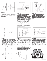
1. After the wheel is removed, remove the brake drum. 2. Using a
1
/2" socket, line up the hole in the axle shaft
flange to remove the backing plate nuts which hold the
axle shaft assembly to the axle.
3. To remove the axle shaft assembly, grasp the axle shaft
assembly with both hands (the assembly includes axle
shaft, oil seal, brake assembly, gasket, bearing, and
retainer) and pull the axle shaft free.
4. Remove inner Axle shaft seal using puller as shown.
Discard Seal and replace with new one at time of
assembly.
5. Place Axle shaft assembly in a vise. Center punch the
outside of the retaining ring.
6. Drill a
1
/4" hole in the outside of the retainer ring to a
depth approximately 3/4 the thickness of the ring.
Drilling Completely through retainer ring will damage
the shaft.
AXLE SHAFT DISASSEMBLY

Service
8
7. After drilling, position a chisel across the hole and
strike sharply to break the ring. Replace with a new
retainer ring when reassembly.
8. Support the axle shaft assembly in a suitable press.
Press on the end of the axle shaft until the wheel
bearing and brake assembly is removed.
1. Inspect the shaft for possible damage. In the following
order, place new oil seal, brake assembly, new grease
packed bearing assembly (with unit bearing rib ring
toward fanged end of shaft) on the axle shaft. The
retaining ring will be placed on the shaft later.
2. Support the bearing assembly in a suitable press.
3. Press assembly until bearing is firmly seated against
axle shaft shoulder.
4. Slide new retaining ring on the axle shaft and support
the shaft in suitable press.
AXLE SHAFT DISASSEMBLY
(CONTINUED)
AXLE SHAFT ASSEMBLY

9
Service
5. Press the retaining ring firmly against bearing. 6. Assembly new grease seal into housing to original
depth. After seal has been assembled, grease lip of
seal.
7. Assemble bearing retainer bolts and new gasket on
axle housing. Then install axle shaft assembly into axle
housing. Care should be taken not to damage gasket,
oil seal, and bearing. Line up holes of brake assembly
and oil seal. Push axle shaft as far as possible into axle
housing.
AXLE SHAFT ASSEMBLY
(CONTINUED)
8. Start nuts on bolts by hand. Tighten nuts in a manner
that assures the seal and bearing assembly are drawn
evenly into axle housing. Use a torque wrench and
torque nuts to 16-20 ft/lb (21-27Nm)

Service
10
SERVICE CHART
Before servicing or making adjustments to the machine, stop engine, set park brak and
remove key from ignition.
Follow all procedures and ONLY use parts prescribed by the manufacturer. Read the engine
manual before maintenance.
C=Check or Clean at specified intervals
R=Replace at specified intervals
* Tire pressure: Front 20 psi (1.4 bar), Rear 18 psi (1.3 bar)
† Torque tire nuts after the first 10 hours and every 200 hours there after (64 to 74 ft/lb (87-100 Nm))
§ Change oil after first 5 hours.
¤ Clean more often under dusty conditions or when airborne debris is present, replace air cleaner parts, if very dirty.
£ Remove cooling shrouds and clean cooling areas more frequently under extremely dusty, dirty conditions.
‡ Gap 0.40 (1.02 mm) Torque to 18-22 ft/lb (24.4-29.8 Nm)
The suggested maintenance checklist is not offered as a replacement for the manufacturer’s engine manual but
as a supplement. You must adhere to the guidelines established by the manufacturer for warranty coverage. In
adverse conditions such as dirt, mud or extreme temperatures, maintenance should be more frequent.
Daily
As Required
100 Hours
200 Hours
250 Hours
300 Hours
400 Hours
Every 500 Hours/Yearly
§ Engine Oil C R R R R R
§ Engine Oil Filter R R R
Engine for Leaks and Loose Parts C C C C C C
¤ Air Cleaner (Paper Element) C C C C C R
¤ Pre-Cleaner (Every 25 hours) CCCCCCR
‡ Spark Plugs R C C R
Idle Speed C C
£ Air Cooling System C C C C C C
Belts and Hoses C C C
* Tire Pressure C C C C C C
Fuel Level C C
Fuel Filter R R
Hydraulic Oil C CC CCR
Hydraulic Oil Filter R R
Hydraulic System for Leaks and Loose Parts C C C C C C
Battery Electrolyte Level C C C C C
Clean Battery Terminals C C
† Torque Lug Nuts C C C
Rear Axle Gear Lube C C C C C
Lubricate C C C C C
Flush Spray Systems Water/Chemical Tanks C C

11
Service
END USER’S SERVICE CHART
C=Check or Clean at specified intervals
R=Replace at specified intervals
* Tire pressure: Front 20 psi (1.4 bar), Rear 18 psi (1.3 bar)
† Torque tire nuts after the first 10 hours and every 200 hours there after (64 to 74 ft/lb (87-100 Nm))
§ Change oil after first 5 hours.
¤ Clean more often under dusty conditions or when airborne debris is present, replace air cleaner parts, if very dirty.
£ Remove cooling shrouds and clean cooling areas more frequently under extremely dusty, dirty conditions.
‡ Gap 0.40 (1.02 mm) Torque to 18-22 ft/lb (24.4-29.8 Nm)
Daily
As Required
100 Hours
200 Hours
250 Hours
300 Hours
400 Hours
Every 500 Hours/Yearly
§ Engine Oil
§ Engine Oil Filter
Engine for Leaks and Loose Parts
¤ Air Cleaner (Paper Element)
¤ Pre-Cleaner (Every 25 hours)
‡ Spark Plugs
Idle Speed
£ Air Cooling System
Belts and Hoses
* Tire Pressure
Fuel Level
Fuel Filter
Hydraulic Oil
Hydraulic Oil Filter
Hydraulic System for Leaks and Loose Parts
Battery Electrolyte Level
Clean Battery Terminals
† Torque Lug Nuts
Rear Axle Gear Lube
Lubricate
Flush Spray Systems Water/Chemical Tanks

Service
12
ADJUSTMENTS
INTERLOCK SWITCH
Located on the front, below the floorboard and behind the clutch. The Interlock Switch is in the electrical circuit
between the starter solenoid and the starter on the ignition switch. When the clutch pedal is depressed, it
pushes the plunger on the interlock switch in, which creates a circuit. Thus allowing the engine to start. When
the clutch pedal is released the plunger on the interlock switch comes out, which breaks the circuit. To adjust,
loosen the two nuts holding the interlock switch and move the interlock switch towards or away from the clutch
pedal as needed.
HYDRAULIC POWER UNIT BELT
Located to the rear and left of the engine. Should have approximately
1
/4" (6.5 mm) of deflection in the center of
the top strand. To adjust, loosen the bolt holding the hydraulic power unit bracket to the frame and adjust the belt
tension as required. Retighten the bolt after the adjustments made.
FOOT CLUTCH BELT
See belt and pulley drawing in this book. Belt retainer should be adjusted so that there is
1
/8" to
1
/4" (3.25 to 6.5
mm) clearance between the belt and retainer with the clutch fully engaged. This is just a starting point. Start the
engine with the transmission in neutral and the park brake set. Engage and disengage the clutch, check to see
if the belt has stopped and is against the retainers. If not shut engine off and readjust the retainers. Adjust the
clutch rods as required to shorten, turn the ball joints in and out to lengthen.
SPRAY PUMP WITH ELECTRIC CLUTCH BELT
Located to the rear and left of the engine. Should have approximately
1
/2" (13 mm) of deflection in the center of
the top strand. Loosen and tighten the
3
/8 - x 2
1
/2 set screw located on the frame pushing against the pump
arm.
PARK BRAKE
Adjust on lever. Adjust on clevis.
BRAKES
Can be adjusted from outside of brake drum with a brake tool.
SPEED CALIBRATION NUMBERS
The speed calibration number for the Spray Star 1602 is 114. This is measured off the drive shaft.
The speed calibration number for the Spray Star 1607 is 621. This is measured off the drive shaft.
STORAGE
If the engine will be out of service for two or more months, use the following storage procedure.
1. Clean the exterior surfaces of the engine.
2. Change the oil and filter while the engine is still warm from operation.
3. The fuel system must be completely emptied, or the gasoline must be treated with a stabilizer to prevent
deterioration.
If you choose to use a stabilizer, follow manufacturers recommendations, and add the correct amount
for the capacity of fuel system. Fill fuel tank with clean, fresh gasoline. Run engine for 2-3 minutes to get
stabilized fuel into carburetor. Close fuel shut-off valve when unit is being stored or transported.
To empty the system, drain fuel tank and carburetor, or run engine until tank and system are empty.
4. Remove the spark plugs. Add one tablespoon of engine oil into each spark plug hole. Install plugs, but
do not connect the plug leads. Crank the engine two or three revolutions.
5. Store machine in a clean, dry place.

13
NOTES

14
Diagrams
HYDRAULIC DIAGRAM

15
Diagrams
HYDRAULIC DIAGRAM PARTS LIST
REF# PART# DESCRIPTION QUANTITY
1 14-352 Hydraulic Hose 54" 1
2 14-351 Hydraulic Hose 46" 1
3 50-456 Hydraulic Cylinder 1
1
/2 x 7 1
14-267 Seal Kit
4 18-171
11
/16 x
9
/16 90° Straight Thread Elbow 3
5 14-355 Hydraulic Hose 81" 1
6 14-354 Hydraulic Hose 84" 1
7 18-306
11
/16 x
9
/16 Straight Thread Connector 5
8 15-315 Hydraulic Power Unit 1
15-315-01 Repair Kit
9 27-059 Filler Breather (part of 15-315) 1
18-314
3
/8 Pipe Coupler 1
18-287
3
/8 Pipe Nipple x 2 1
10 HBM-6-16 Metric Bolt M6 - 1 x 16 4
HWLM-6 Lockwasher M6 4
11 15-301 Orbitor 1
15-301-01 Seal Kit
12 18-309 Swivel Nut 1
FITTING TORQUE CHARTS
Over tightened fittings will result in crushing the cone which will create a leak.
Charts Developed by Parker Henniphin
Port Side
in. lbs. ft. lbs. ft. lbs.
4
9
/
16
- 18 220 18 15
6
11
/
16
- 16 360 30 35
8
13
/
16
- 16 480 40 60
10 1-14 60 100
12 1
3
/
16
- 12 85 135
14 1
5
/
16
- 12 95 175
16 1
7
/
16
- 12 110 200
20 1
11
/
16
- 12 140 250
24 2 - 12 180 305
32 2
1
/
2
- 12 360 375
Tube Side
Fitting
Size
SAE Tube
Thread
Size
Seal-Lok Strai
g
ht and Adjustable Fittin
g
(Steel)Torque Ratings

16
Diagrams
WIRING DIAGRAM
Color Code Chart
Bl Blue
Br Brown
Y Yellow
Grn Green
O Orange
R Red
B Black
P Purple
W White
G/W Green &
White
Use dielectric grease on all electrical connections.
To reset circuit breaker on ball valve, you must disconnect power to the computer.
Boom Lift 20 AMP 33-272
Spray System 15 AMP 33-508
Manifold Valve 5 AMP 33-284
Foamer 10 AMP 33-507
Hose Reel 30 AMP 33-273
FUSES

17
Diagrams
WIRING DIAGRAM PARTS LIST
REF# PART# DESCRIPTION QUANTITY
1 34-146 Panel Mounted Circuit Breaker 1
34-145 Circuit Breaker Boot 1
2 8935 Buss Bar (-) 1
3 13-288 Ignition Switch (Kohler 25 099 04)(part of engine) 1
76-310 Key Set 1
4 16-882 Speedometer 1
8854 Fork Terminal 2
8962 Heat Shrink 2
5 14-332 Speedometer Ground Wire 1
6 16-883 Magnetic Sensor 1
7 14-333 Speedometer B+ Wire 1
8 8935 Buss Bar(+) 1
9 14-331 Hour / Voltmeter Ground Wire 1
10 42-064 Hour / Voltmeter Combo 1
11 14-330 Hour / Voltmeter B+ Wire 1
12 Oil Sender (part of engine)
13 Ignition Module (part of engine)
14 Fuel Shut-Off Solenoid (part of engine)
15 Rectifier (part of engine)
16 Starter (part of engine)
17 50-323 Red Battery Cable 1
18 33-216 Battery (optional) 1
19 22-054 Ground Battery Cable 1
20 15-484 Wire Assembly Fuse Block To + Bat. (on solenoid) 1
21 15-485 Wire Assembly Fuse Block To Ground 1
22 33-271 Fuse Block 1
23 Wire With Fuse (part of engine)
Fuse AGC 30
24 22-002 Interlock Switch 1
25 14-334 Ignition Switch Ground Wire 1
26 33-480 Pressure Switch 1
27 16-989 Hypro Pump With Electric Clutch 1
8958 Male Slide on Terminal 1
8962 Heat Shrink
3
/16 1
28 15-457 Ground Wire 1
29 77-207 Buzzer 1
8849-3 Black Wire 1
8860 String Connector 1
8859 Ring Terminal
3
/16 1
8853 Slide On Connector 1
8962 Heat Shrink 2
8963 Heat Shrink 1
30 14-335 Spray Pump Switch B+ Wire 1
31 15-314 Toggle Switch 1
15-472 Switch Boot 1
32 50-359 Oil Warning Light 1
8850-12 Red Wire 1
8860 String Connector 1
8859 Ring Terminal
3
/16 1
8958 Male Slide On Terminal 1
8962 Heat Shrink
3
/16 2
8963 Heat Shrink ¼ 1
N.S. 22-017 Cable Black (transmission to frame) 1
14-336 Main Wire Harness
(Includes all wire colors with *) 1

18
Diagrams
HYDRAULIC SCHEMATIC
/