Page is loading ...

User’s manual
www.euphones.vtech.com
LS1250-B

1
1. IMPORTANT SAFETY INSTRUCTIONS
When using your telephone equipment, basic safety precautions should always
be followed to reduce the risk of re, electric shock and injury, including the
following:
Read and understand all the instructions.
Follow all warnings and instructions marked on the product.
Unplug this product from the wall outlet before cleaning. Do not use liquid
cleaners or aerosol cleaners. Use a damp cloth for cleaning.
Do not use this product near water (for example, near a bath tub, kitchen
sink, swimming pool).
Do not expose the telephone to direct sunlight or extreme cold environment.
Do not put the telephone close to heating sources such as radiators,
cookers, etc.
Do not overload wall outlets and extension cords as this can result in the risk
of re or electric shock.
Unplug this product from the wall outlet and refer servicing to VTech/
distributor under the following conditions:
When the power supply cord or plug is damaged or frayed.
If the product does not operate normally by following the operating
instructions.
If the product has been dropped and the cabinet has been damaged.
If the product exhibits a distinct change in performance.
Avoid using a telephone (other than a cordless type) during an electrical
storm. There may be a remote risk of electric shock from lightning.
Do not use the telephone to report a gas leak in the vicinity of the leak.
Use only the supplied NiMH (Nickel Metal Hydride) batteries! The operation
periods for the handsets are only applicable with the default battery
capacities.
The use of other battery types or non-rechargeable batteries/primary cells
can be dangerous. These may cause interference and/or unit damages. The
manufacturer will not be held liable for damage arising from such
non-compliance.
Do not use third party charging bays. The batteries may be damaged.
Please note the correct polarity while inserting the batteries.
Battery should not be exposed to excessive heat such as bright sunshine or
re and immersed in water.
1.
2.
3.
4.
5.
6.
7.
•
•
•
•
8.
9.
10.
11.
12.
13.
14.

2
DISPOSAL WARNING
When this crossed-out wheeled bin symbol is attached to a
product, it means the product is covered by the European
Directive 2002/96/EC.
All electrical and electronic products/battery should be disposed
of separately from the municipal waste stream via designated
collection facilities appointed by the government or the local
authorities.
The correct disposal of your old appliance/battery will help prevent potential
negative consequences for the environment and human health.
For more detailed information about disposal of your old appliance/battery,
please contact your city ofce, waste disposal service or the shop where you
purchased the product.
If you have questions about this product, or having difculty with setup or
operation, contact our Customer Service Centre.
POWER ADAPTOR INFORMATION
Power
adaptor
Ten Pao International Ltd. - Model: S003IV0600045,
Input 100-240V AC 50/60Hz 150mA,
Output 6VDC 450mA (EU plug).
Battery Handset: NI-MH PACK x1, 2.4V, 750mAh
Doorbell: ALKALINE CELL, AAx2, 1.5V; 2800mAh
For pluggable equipment, the socket outlet shall be installed near the equipment
and shall be easily accessible.
1.
2.
3.

3
2. SET UP THE TELEPHONE
2.1 Package Contents
The package contains the following items:
Telephone base and power adapter
Handset (1 for IS7121A, 2 for IS7121-2A)
Handset charger and charger adapter (1 for IS7121-2A)
Doorbell with wall mount cover
Telephone Wall mount bracket
Battery compartment cover (1 for IS7121A, 2 for IS7121-2A)
NiMH Rechargeable battery pack (1 for IS7121A, 2 for IS7121-2A)
AA Alkaline batteries (2)
Screw for doorbell (bottom)
Screw for doorbell (wall mount)
Wall anchors
Double-sided adhesive tape
Telephone line cord
User’s manual
Warranty card
•
•
•
•
•
•
•
•
•
•
•
•
•
•
•
4
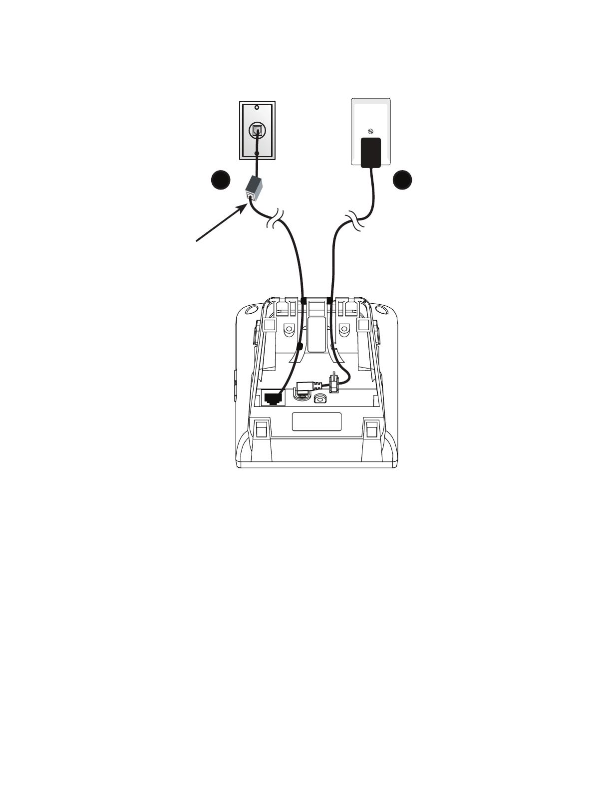
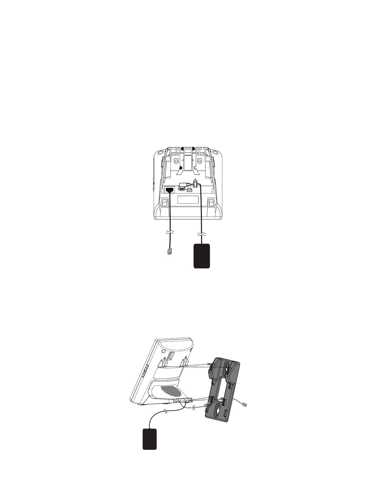
2.2 Connect the Base Station
note
Use only the supplied power adapter.•
A DSL lter (not
included) is required
if you have DSL high-
speed Internet service.
The DSL lter must
be plugged into the
telephone wall jack.
To telephone
wall jack
To wall power
outlet
1
2
5
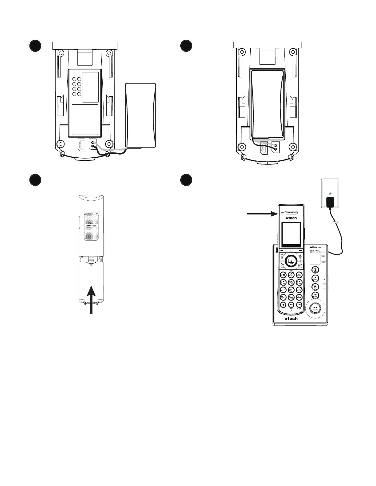
2.3 Install and Charge the Handset Batteries
notes
Use only the supplied NiMH rechargeable batteries.
If you do not use the handset for a long time, disconnect and remove the
batteries to prevent possible leakage.
•
•
Battery Pack
BT164392/BT264392
2.4V 550mAh Ni-MH
WARNING : DO NOT BURN OR
PUNCTURE BATTERIES
Made in China CR1222
1 2
3 4
CHARGE light
remains on
when charging.
Battery Pack / Bloc-piles :
(2.4V Ni-MH)
WARNING / AVERTISSEMENT :
DO NOT BURN OR PUNCTURE BATTERIES.
NE PAS INCINÉRER OU PERCER LES PILES.
Made in China / Fabriqué en chine
THIS SIDE UP / CE CÔTÉ VERS LE HAUT
CR1232
Battery Pack / Bloc-piles :
(2.4V Ni-MH)
WARNING / AVERTISSEMENT :
DO NOT BURN OR PUNCTURE BATTERIES.
NE PAS INCINÉRER OU PERCER LES PILES.
Made in China / Fabriqué en chine
THIS SIDE UP / CE CÔTÉ VERS LE HAUT
CR1232
6
2.4 Installation Options
Your telephone base is ready for tabletop use. If you want to mount your telephone
on a wall, follow the steps below to connect the telephone base with a standard
dual-stud telephone wall mounting plate. You may need a professional to install the
wall mounting plate.
2.4.1 Tabletop to Wall Mount Installation
If you have already installed the telephone for tabletop use, unplug the
telephone line cord from the telephone wall jack, and unplug the telephone
base power adapter from the wall outlet. Remove the telephone line cord and
the power adapter cord from the grooves.
1.
2. Route the telephone line cord through the rectangular hole on the wall mount
bracket. Position the lower portion grooves on the telephone base to the lower
portion tabs on the wall mount bracket. Make sure the upper portion grooves
of the telephone base are above the upper portion tabs on the wall mount
bracket. Push the telephone base down until it clicks securely in place.
7
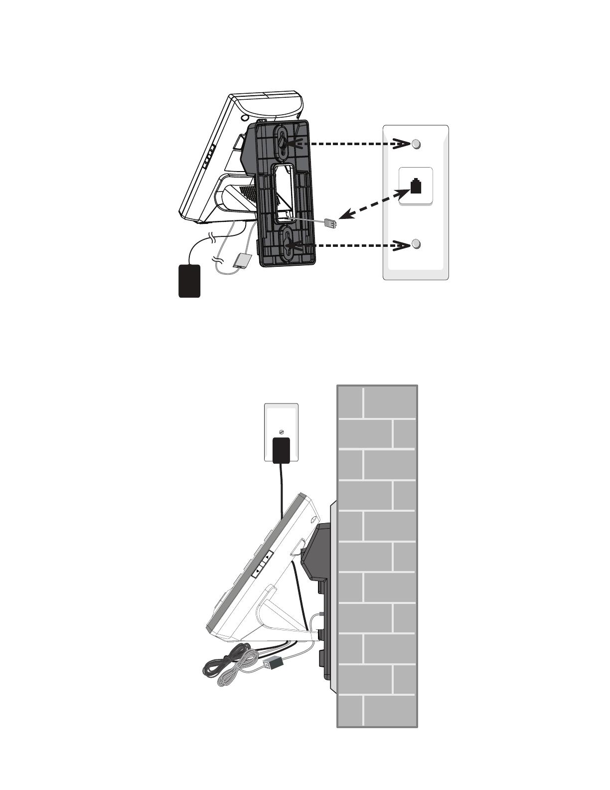
3. Plug the telephone line cord into the telephone wall jack or DSL lter. Align the
holes on the bracket with the standard wall plate and slide the bracket down
until it locks securely.
4. Plug the power cord into an electrical outlet not controlled by a wall switch.
Bundle the telephone line cord and power adapter cord neatly with twist ties.

8
2.4.2 Wall Mount to Tabletop Installation
To change the telephone base from the wall mount position to tabletop position,
follow the steps below.
If the telephone line cord and power adapter cord are bundled, untie them rst.
Slide the wall mount bracket up and remove it from the wall plate. Unplug the
telephone line cord (or DSL lter) from the wall. Unplug the power adapter from
the power outlet.
Slide the telephone base up and remove it from the wall mount bracket.
See section Connect the Base Station.
1.
2.
3.
4.
9
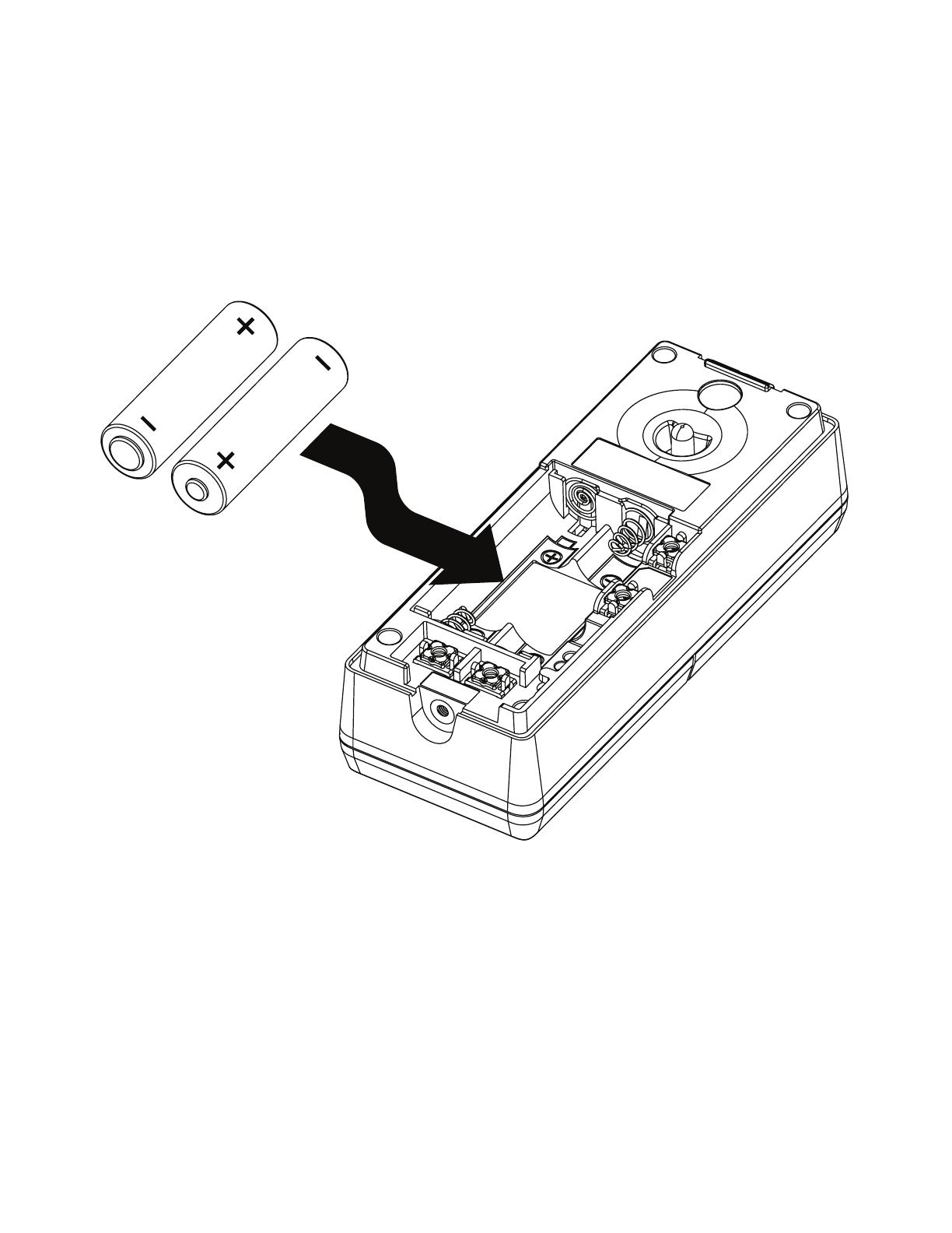
2.5 Doorbell Battery Installation
Remove the wall mount cover at the back.
Install two AA batteries into the battery compartment, matching the polarity
markings (+ and -) inside the battery compartment.
1.
2.
10
2.6 Locating the Doorbell
Before mounting the doorbell on a wall, make sure you test if the location you
install the doorbell is in range, and adjust the camera angle to best suit your needs.
To test the location for installation:
Hold the doorbell in the location where you want to install the doorbell, then follow
the steps below to test the reception range and video capture angle.
Press MENU →
p
q
→ Settings → SELECT.
Press
p
q
→ Doorbell setup → SELECT.
Press /DOORBELL → check video streaming quality.
Press NEXT.
Press ISO → + / - → adjust video streaming brightness.
If audio feedback occurs, press on the handset to turn off the
speakerphone.
If the desired location is in good range, the handset displays .
If the desired location is not in good range, the handset ashes in red.
Press INFO for instructions to relocate your handset and/or telephone
base. When the reception is in good range, the handset displays . Press
OK to return to the video streaming.
6. Keep the video streaming on for camera lens adjustment.
1.
2.
3.
4.
5.
•
•
•

11
Avoid mounting it to where reections may be caused by sunlight, for example,
opposite to a white wall.
Two built-in infrared LEDs are for night vision. Make sure the surrounding light
source is sufcient for infrared operation.
•
•
Infrared LEDs
When nding a desirable location for the doorbell:
Make sure the visitor is standing in a reasonable distance away from the
doorbell.
Avoid mounting it on a location which is subjected to vibration or shock.
Avoid mounting it on an enclosed area where it may cause echoes.
Avoid mounting it to where it is exposed to direct sunlight.
•
•
•
•
12
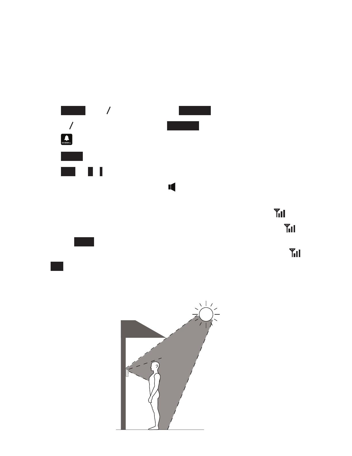
The diagrams below demonstrate an example of doorbell camera position to view
a visitor about 20 inches from the camera. The camera in this example is set in
default angle (0 degree).
You may move the lever at the back of the doorbell to adjust the shooting area
(the camera lens).
Test at the front door to determine when the infrared LEDs turn on. When they are
in operation, they turn red.
To adjust the shooting area, you may either relocate the doorbell in different
height level, or adjust the camera angle (see below).
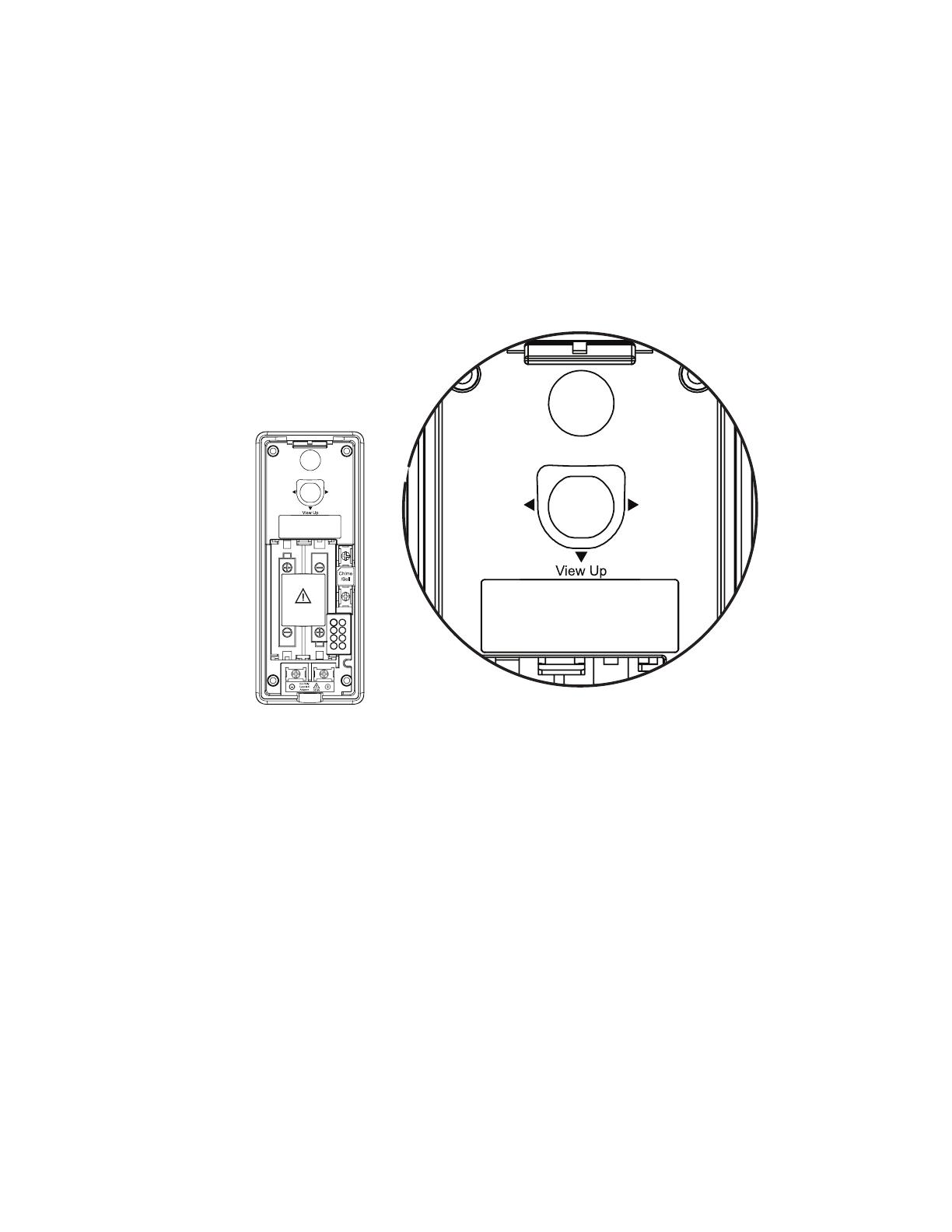
To adjust the camera angle:
Tilt the lever to adjust the angle of the camera lens. The camera lens can be
adjusted to left, right or down, up to 10 degrees.
•
View
Right
Angle
Adjustment
View
Left
CAUTION
View
Right
Angle
Adjustment
View
Left
CAUTION
13
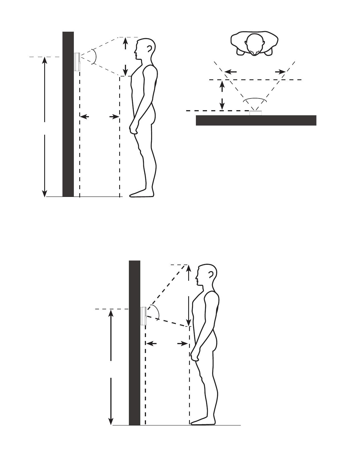
You may install the doorbell in a lower position. The diagram below demonstrates
an example of doorbell camera position to view a visitor about 20 inches from the
camera. The camera in this example is set in 10 degrees angle upward.
Side view
20
inches
50
degrees
19
inches
Shooting area
43
inches
Top view
Shooting area
19.7 inches
60 degrees
22.8 inches
Shooting area
19.7
inches
50 degrees
18.3
inches
63 inches
60 degrees
Shooting area
23 inches
20 inches
Side view
18
inches
50 degrees
63 inches
20
inches
Shooting area

14
You may install the doorbell on the left or right side. The diagram below
demonstrates an example of doorbell camera position to view a visitor about 20
inches from the camera. The camera in this example is set in 10 degrees angle to
the right.
Top view
Shooting area
19.7 inches
60 degrees
22.8 inches
Shooting area
19.7
inches
50 degrees
18.3
inches
63 inches
60 degrees
Shooting area
24 inches
20 inches
After you have tested the reception range and found the desirable location to
install the doorbell, press END on the handset to end the video streaming and
proceed to Install the Doorbell Wall Mount Cover and Install the Doorbell.
15
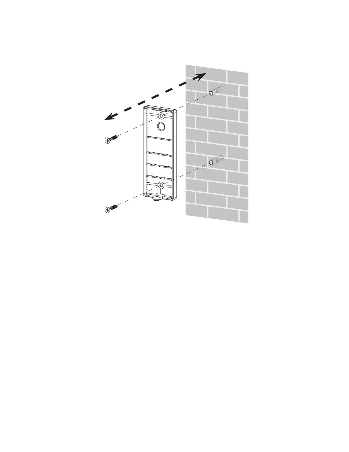
2.7 Install the Doorbell Wall Mount Cover
Make sure to test the reception and the doorbell position before you mount the
doorbell on the wall. See Locating the doorbell to choose a desirable position
for the doorbell.
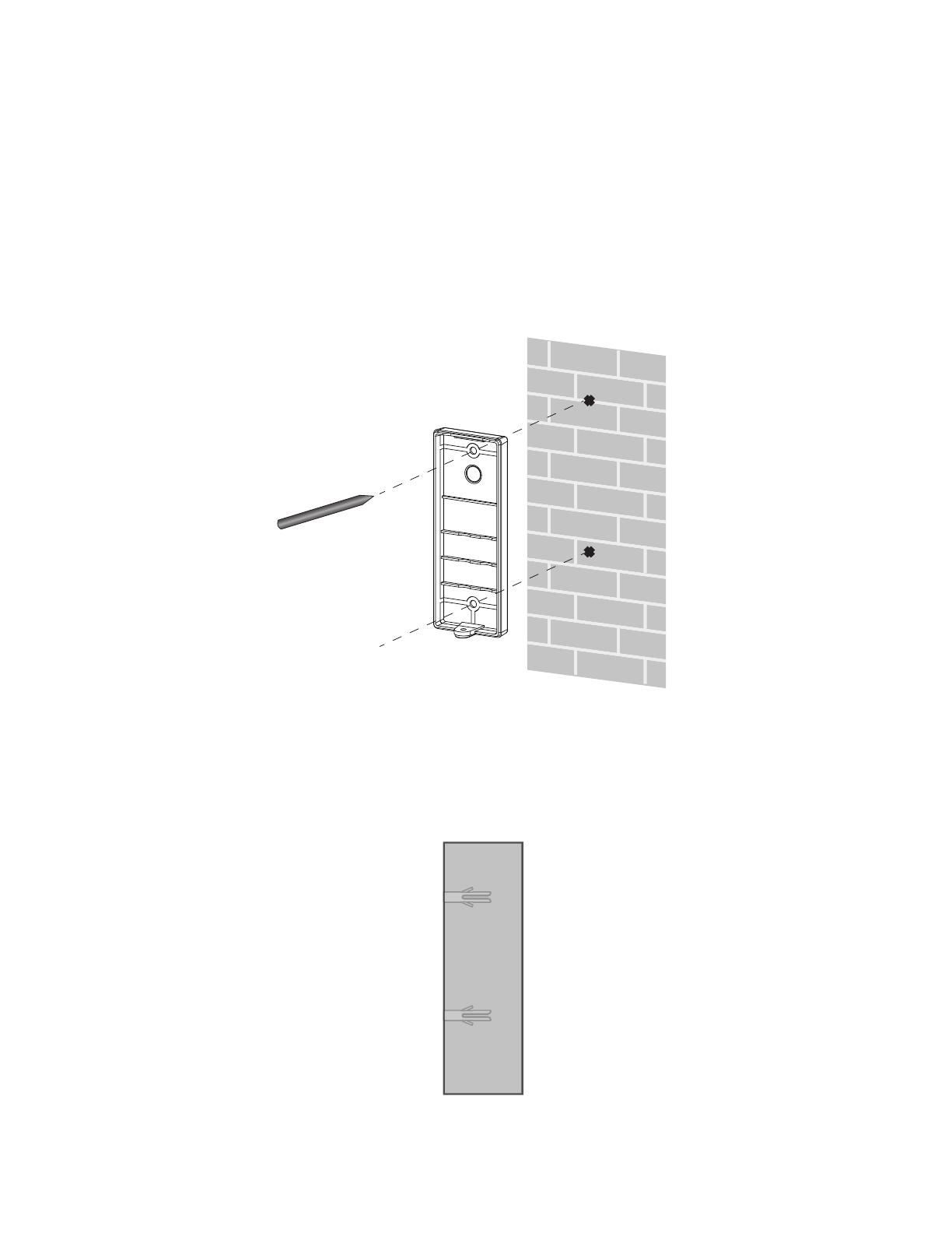
Use a pencil to mark two holes on the desired location. Then remove the wall
mount and drill two holes in the wall. Check for reception strength and camera
angle before drilling the holes.
1.
2. Place the wall anchors into the holes, and tap gently on the ends with a
hammer, until the wall anchors are ush with the wall.
16
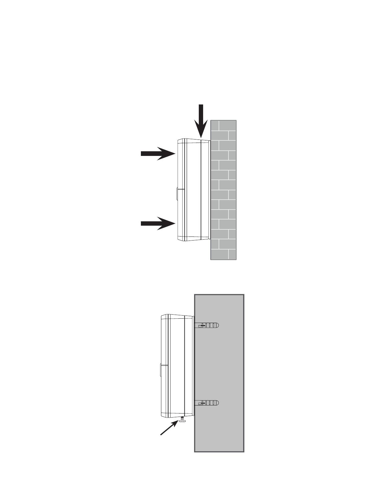
Align the holes on the wall mount cover with the holes on the wall (or stud).
Tighten the screws into the holes to secure the wall mount cover onto the wall.
3.
17
Push the doorbell gently onto the wall mount until they are sealed tightly.
This doorbell meets the IPX4 waterproof standard. Make sure the doorbell
is tightly sealed with its wall mount cover in order to maintain its waterproof
ability.
1.
Tighten the screw into the threaded socket at the bottom to secure.2.
Screw
Push
Push
Seal tightly
2.8 Install the Doorbell

18
2.9 Detach Doorbell From Wall Mount Cover
After an extended exposure to cold, heat or humidity, the doorbell gasket rubber
may become sticky.
If you need to remove the doorbell from its wall mount cover in case of battery
replacement or doorbell relocation, follow the steps below.
Remove the screw at the bottom.1. Insert a at-bladed screwdriver
between the doorbell and its
wall mount cover to pry open at
both sides.
2.
Pry the doorbell off.3.
19
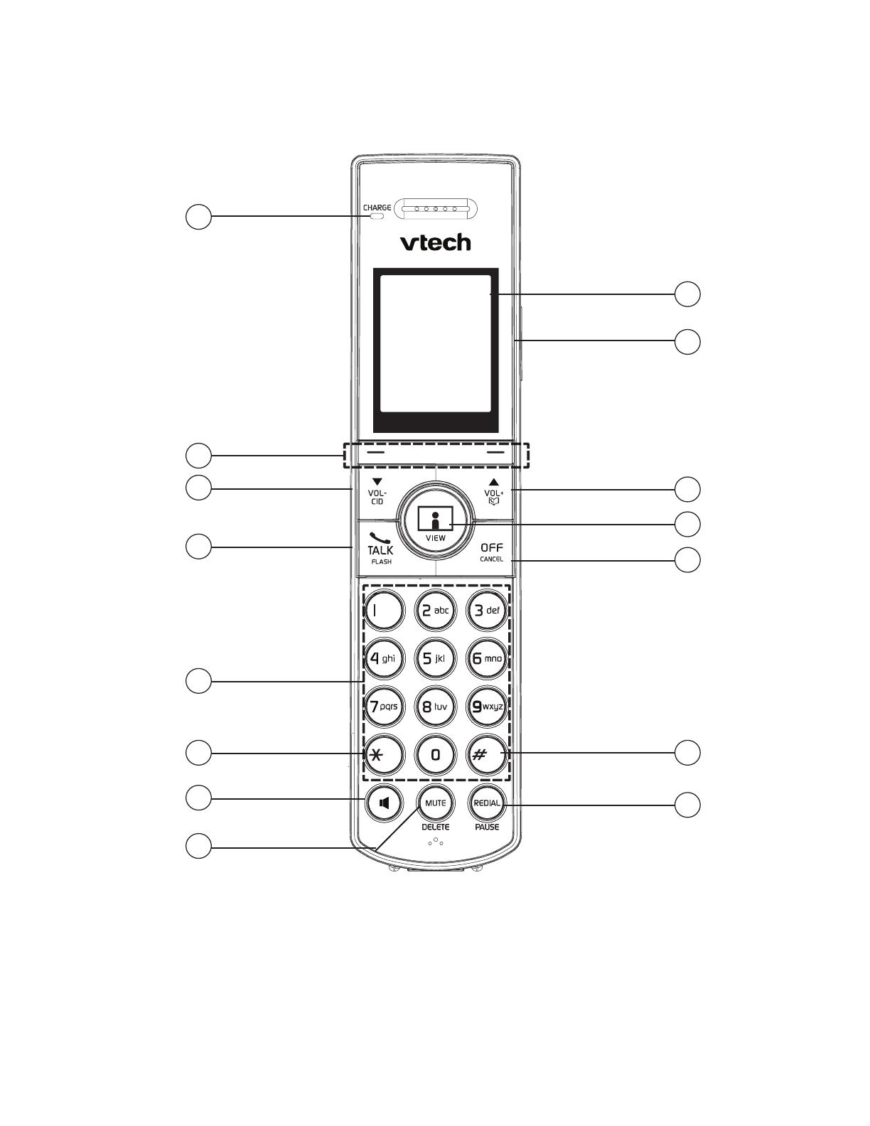
3. GET TO KNOW YOUR PHONE
3.1 Overview of the Handset
CHARGE light
On when the handset is charging in the telephone base.
Soft keys (2)
Press to select a menu item displayed above the key.
1.
2.
1
2
3
4
6
7
5
8
9
11
14
15
12
13
10
/