Page is loading ...

Complete user’s manual
w w w.v t e c h p h o n e s . c o m
Models:
IS7121/IS7121-2/
IS7121-22
BC

Congratulations
on purchasing your new VTech product. Before using this telephone, please read
Important safety instructions on page 102 of this manual.
This manual has all the feature operations and troubleshooting necessary to install
and operate your new VTech telephone. Please review this manual thoroughly to
ensure proper installation and operation of this innovative and feature rich VTech
product. For support, shopping, and everything new at VTech, visit our website at
www.vtechphones.com. In Canada, please visit www.vtechcanada.com.
The ENERGY STAR
®
program (www.energystar.gov) recognizes
and encourages the use of products that save energy and help
protect our environment. We are proud to mark this product with
the ENERGY STAR
®
label indicating it meets the latest energy
efciency guidelines.
T
Compatible with
Hearing Aid T-Coil
TIA-1083
Telephones identied with this logo have reduced noise and
interference when used with most T-coil equipped hearing aids and
cochlear implants. The TIA-1083 Compliant Logo is a trademark of
the Telecommunications Industry Association. Used under license.
Register online to get an additional 3-month warranty!
Visit www.vtechphones.com.
Registration
Register your product online for enhanced
warranty support.
Product news
Learn about the latest VTech products.

i
Table of contents
Getting started .............................1
Parts checklist ....................................1
Telephone base and charger
installation .......................................2
Handset battery installation ................3
Handset battery charging ...................4
Are you a new cable or VoIP
subscriber?......................................5
Did you subscribe to voicemail
service from your telephone
service provider? .............................5
Installation options ..............................6
Tabletop to wall mount installation .....6
Wall mount to tabletop installation ......8
Doorbell battery installation ................9
Locating the doorbell ........................10
Doorbell installation ..........................14
Detach doorbell from wall mount
cover .............................................18
Installing the doorbell with an
existing wired doorbell...................19
Telephone base layout .....................22
Handset layout..................................24
Doorbell layout..................................26
Using the menu ................................27
Telephone settings ...................28
Handset ringer volume .....................28
Telephone base ringer volume .........28
Ringer tone .......................................28
Chime volume...................................29
Chime tone .......................................29
Quiet mode .......................................30
Set date and time .............................31
LCD language...................................32
CID time synchronization..................33
Rename devices ...............................34
Voice Announce
®
caller ID ................35
LCD brightness .................................36
Dim mode .........................................36
Wallpaper .........................................36
Voicemail number .............................37
Clear voicemail indicators.................38
Key tone ...........................................39
Dial mode .........................................39
Home area code ...............................40
Doorbell operation ....................41
Answer a chime ................................41
Start a video streaming session .......41
Extend a video streaming session ....42
End a video streaming session.........42
Answer an incoming call during
video streaming .............................42
View captured photos .......................43
Delete a captured photo ...................43
Delete all captured photos ................43
Night vision .......................................43
Telephone operation .................44
Make a call .......................................44
Predial a call .....................................44
Answer a call ....................................44
End a call ..........................................44
Handset speakerphone ....................44
Volume control..................................45
Mute..................................................45
Call waiting .......................................45
Temporary ringer silencing ...............45
Temporary tone dialing .....................46
Chain dialing .....................................46
Check voicemail ...............................47
Find handset .....................................47
Website.............................................47
Redial ...............................................48
Equalizer...........................................48
Transfer a call ...................................49

ii
Table of contents
Multiple handset use .................50
Join a call in progress .......................50
Intercom............................................51
Answer an incoming call during
an intercom call .............................52
Call transfer using intercom ..............53
Push-to-talk (PTT) ............................54
PTT on/off .........................................54
PTT to a single handset....................55
PTT to multiple handsets ..................56
Answer a PTT call ............................57
Change a one-to-one PTT to
intercom call ..................................57
End a PTT call ..................................58
Answer an incoming call during
a PTT call ......................................58
Make an outgoing call during
a PTT call ......................................58
Directory .....................................59
About the directory ...........................59
Add a directory entry ........................60
Review directory entries ................... 62
Alphabetical search ..........................62
Dial a directory entry.........................63
Edit a directory entry.........................63
Delete a directory entry ....................63
Speed Dial ........................................64
Assign a speed dial slot ....................64
Reassign a speed dial slot................65
Dial a speed dial number ..................65
Delete a speed dial entry ..................65
Caller ID ......................................66
About caller ID ..................................66
Information about caller ID with
call waiting.....................................66
Caller ID log ......................................67
Memory match ..................................67
Missed call indicator .........................68
Review the caller ID log ....................68
View dialing options ..........................69
Dial a caller ID log entry ...................70
Save a caller ID log entry to
the directory ..................................70
Delete caller ID log entries ...............71
Caller ID log screen messages.........71
Answering system settings......72
Answering system ............................72
Announcement .................................72
Record your own announcement......72
Play your announcement ..................73
Delete your announcement ..............73
Answer on/off....................................74
Call screening ...................................75
Number of rings ................................75
Remote access code ........................76
Message alert tone ...........................76
Recording time .................................77
Answering system operation ...78
Answering system and voicemail .....78
Using the answering system and
voicemail together .........................78
Message capacity .............................79
New message indication...................79
Call screening ...................................80
Call intercept.....................................80
Temporarily turn off the message
alert tone .......................................80
Message playback ............................81
Delete all old messages ...................83
Record, play and delete memos .......83
Remote access .................................84

iii
Table of contents
Appendix ....................................85
Expand your telephone system ........85
Add and register a handset ..............85
Add and register a doorbell ..............86
Deregister handsets and doorbells ...87
Screen messages .............................88
Handset and telephone base
indicators .......................................90
Battery ..............................................91
Troubleshooting ................................92
Important safety instructions...........102
Precautions for users of
implanted cardiac pacemakers ...103
Operating range..............................103
ECO mode ......................................103
Energy-saving charging mode ........104
Maintenance ...................................104
About cordless telephones .............105
The RBRC
®
seal .............................105
FCC, ACTA and IC regulations ......106
Limited warranty .............................108
Technical specications..................110
Index .........................................111

1
To purchase replacement batteries or power adapters, visit our website at
www.vtechphones.com or call 1 (800) 595-9511. In Canada, go to
www.vtechcanada.com or dial 1 (800) 267-7377.
Parts checklist
Your telephone package contains the following items. Save your sales receipt and original
packaging in case it is necessary to ship your telephone for warranty service.
Getting started
Abridged user’s manual
Abridged user’s manual
Battery
(1 for IS7121)
(2 for IS7121-2/IS7121-22)
Battery compartment
cover
(1 for IS7121)
(2 for IS7121-2/IS7121-22)
Handset
(1 for IS7121)
(2 for IS7121-2/IS7121-22)
Screws for doorbell
wall mount
(2 for IS7121/IS7121-2)
(4 for IS7121-22)
Telephone base
Screw for doorbell
(bottom)
(1 for IS7121/IS7121-2)
(2 for IS7121-22)
Telephone base
power adapter
Wall anchors
(2 for IS7121/IS7121-2)
(4 for IS7121-22)
Telephone
line cord
Doorbell power
adapter
(1 for IS7121/IS7121-2)
(2 for IS7121-22)
Handset charger
and charger adapter
(1 for IS7121-2/IS7121-22)
Doorbell with wall
mount cover
(1 for IS7121/IS7121-2)
(2 for IS7121-22)
Wall mount bracket Alkaline batteries
(2 for IS7121/IS7121-2)
(4 for IS7121-22)
Installation guide
Installation guide
Battery Pack / Bloc-piles :
(2.4V Ni-MH)
WARNING / AVERTISSEMENT :
DO NOT BURN OR PUNCTURE BATTERIES.
NE PAS INCINÉRER OU PERCER LES PILES.
Made in China / Fabriqué en chine
THIS SIDE UP / CE CÔTÉ VERS LE HAUT
CR1232

Getting started
2
Telephone base and charger installation
Install the telephone base and charger(s) as shown below.
Make sure that the electrical outlet is not controlled by a wall switch.
If you subscribe to digital subscriber line (DSL) high-speed Internet service through
your telephone line, you must install a DSL filter between the telephone line cord and
the telephone wall jack. The filter prevents noise and caller ID problems caused by
DSL interference. Contact your DSL service provider for more information about
DSL filters.
Telephone wall jack
Telephone base
power adapter
Telephone
line cord
Telephone base
Electrical outlet
(not controlled by
a wall switch)
A DSL lter (not
included) is required if
you have DSL high-
speed Internet service.
The DSL lter must
be plugged into the
telephone wall jack.
Charger
Charger adapter
CAUTION:
If you subscribe to telephone service from a cable company or a VoIP service
provider, plug the telephone line cord into the modem/router/terminal adapter provided
by your cable/VoIP service provider. Contact your cable/VoIP service provider if you
have any difculties in installation.
Use only the power adapters supplied with this product. To order a replacement, visit
our website at www.vtechphones.com or call 1 (800) 595-9511. In Canada, go to
www.vtechcanada.com or call 1 (800) 267-7377.
The power adapters are intended to be correctly oriented in a vertical or floor mount
position. The prongs are not designed to hold the plug in place if it is plugged into a
ceiling, under-the-table or cabinet outlet.
•
•

Getting started
3
Handset battery installation
Install the battery as shown below.
If the handset will not be used for a long time, disconnect and remove the battery to
prevent possible leakage.
To purchase replacement batteries, visit our website at www.vtechphones.com
or call 1 (800) 595-9511. In Canada, go to www.vtechcanada.com or dial
1 (800) 267-7377.
•
•
Insert the battery connector securely
into the socket, matching the
orientation of the engraved label.
1. Place the battery with the label
THIS SIDE UP facing up and the wires
inside the battery compartment.
2.
Align the cover flat against the
battery compartment, then slide it
towards the center of the handset
until it clicks into place.
3. Charge the handset by placing it in
the telephone base or charger. The
CHARGE light is on when the handset
is charging.
4.
Battery Pack
BT164392/BT264392
2.4V 550mAh Ni-MH
WARNING : DO NOT BURN OR
PUNCTURE BATTERIES
Made in China CR1222
Battery Pack / Bloc-piles :
(2.4V Ni-MH)
WARNING / AVERTISSEMENT :
DO NOT BURN OR PUNCTURE BATTERIES.
NE PAS INCINÉRER OU PERCER LES PILES.
Made in China / Fabriqué en chine
THIS SIDE UP / CE CÔTÉ VERS LE HAUT
CR1232
Battery Pack / Bloc-piles :
(2.4V Ni-MH)
WARNING / AVERTISSEMENT :
DO NOT BURN OR PUNCTURE BATTERIES.
NE PAS INCINÉRER OU PERCER LES PILES.
Made in China / Fabriqué en chine
THIS SIDE UP / CE CÔTÉ VERS LE HAUT
CR1232
CHARGE light
remains on
when charging.
IMPORTANT:
Check for a dial tone by pressing . If you hear a dial tone, the installation is successful.
If you do not hear a dial tone:
Make sure the installation procedures described above are properly done.
It may be a wiring problem. If you have changed your telephone service to digital service
from a cable company or a VoIP service provider, the telephone line may need to be rewired
to allow all existing telephone jacks to work. Contact your cable/VoIP service provider for
more information.
•
•

Getting started
4
Handset battery charging
Once you have installed the battery, the screen indicates the battery status (see the
table below). If necessary, place the handset in the telephone base or charger to
charge the battery. For best performance, keep the handset in the telephone base
when not in use. The battery is fully charged after 11 hours of continuous charging. See
the table on page 91 for battery operating times.
If the screen is blank or displays Place in charger, you need to charge the handset
without interruption for at least 30 minutes to give the handset enough charge to
use the telephone for a short time. When the battery is low, the handset displays
Low battery along with a flashing icon. If you are on a call in low battery mode, the
handset plays short beeps to alert you.
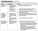
The following table summarizes the battery charge indicators and actions to take.
Battery indicators Battery status Action
The screen is blank, or
displays Place in charger
and flashes.
The battery has no or very
little charge. The handset
cannot be used.
Charge without interruption
(about 30 minutes).
The screen displays
Low battery and flashes.
The battery has enough
charge to be used for a
short time.
Charge without interruption
(about 30 minutes).
The screen displays
HANDSET 1.
The battery is charged. To keep the battery charged,
place it in the telephone
base when not in use.
If you place the handset in the telephone base without installing a battery, the
screen displays No battery.
After you install your telephone or power returns following a power
outage, the handset will prompt you to set the date and time. For
instructions, see Set date and time on page 31.
To skip setting the date and time, press CANCEL.
SET DATE
MM/DD/YY
BACK SET

Getting started
5
Are you a new cable or VoIP subscriber?
If your answer is yes, the existing telephone jacks in your home may no longer work.
Your cable/VoIP service provider uses a different connection, separate from your old
traditional telephone service, to connect the modem/router/terminal adapter installed in
your home.
To allow all existing telephone jacks to work, contact your telephone service provider
for solutions, such as rewiring services (fees may apply).
If your answer is no, your existing telephone jacks will continue to work as normal.
OLD
Conventional
telephone line jack
Main
landline
NEW
Modem/Router/
Terminal adapter
Cable or
Internet
Did you subscribe to voicemail service from your telephone
service provider?
Your telephone has a built-in answering system and supports voicemail feature offered
by your telephone service provider (subscription is required, and fees may apply).
Refer to Answering system and voicemail on page 78 for more details.
To use the built-in answering system:
You may see this online Complete user’s manual on how to record your outgoing
announcement, retrieve messages and other related operations. You may also refer to
the Abridged user’s manual in the product package for abbreviated instructions.
To use the voicemail:
To retrieve your voicemail messages, you typically dial an access number provided
by your telephone service provider, and then enter a security code. Contact your
telephone service provider for instructions on how to configure the voicemail settings
and listen to messages.

Getting started
6
Installation options
Your telephone base is ready for tabletop use. If you want to mount your telephone
on a wall, use the provided wall mount bracket to connect with a standard dual-
stud telephone wall mounting plate. If you do not have this mounting plate, you can
purchase one from many hardware or consumer electronics retailers. You may need a
professional to install the mounting plate.
Tabletop to wall mount installation
If you have already installed the telephone for tabletop use, unplug the telephone
line cord from the telephone wall jack, and unplug the telephone base power
adapter from the wall outlet. Remove the telephone line cord and the power adapter
cord from the grooves.
1.
Route the telephone line cord through the rectangular hole on the wall mount
bracket. Position the lower portion grooves on the telephone base to the lower
portion tabs (marked B) on the wall mount bracket. Make sure the upper portion
grooves of the telephone base are above the upper portion tabs (marked A) on the
wall mount bracket. Push the telephone base down until it clicks securely in place.
2.

Getting started
7
Plug the telephone line cord into the telephone wall jack or DSL lter. Align the
holes on the bracket with the standard wall plate and slide the bracket down until it
locks securely.
3.
Tabletop to wall mount installation
Plug the power cord into an electrical outlet not controlled by a wall switch. Bundle
the telephone line cord and power adapter cord neatly with twist ties.
4.

Getting started
8
Wall mount to tabletop installation
If the telephone line cord and power adapter cord are bundled, untie them rst.
Slide the wall mount bracket up and remove it from the wall plate. Unplug the
telephone line cord (or DSL lter) from the wall. Unplug the power adapter from the
power outlet.
Slide the telephone base up and remove it from the wall mount bracket.
See Telephone base and charger installation on page 2.
1.
2.
3.
4.

Getting started
9
For longer battery life, lithium batteries (not provided) are recommended. Lithium
batteries provide approximately 30% additional battery life than alkaline batteries.
•
Doorbell battery installation
You can power up the doorbell by connecting it to the domestic power supply or two
AA alkaline batteries (provided). Even if the doorbell is connected to the domestic
power supply, we recommend you also install two AA alkaline batteries. This
guarantees continual operation in case of a power outage.
Install two AA batteries into the battery compartment, matching the polarity markings
(+ and -) inside the battery compartment.

Getting started
10
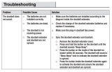
Locating the doorbell
Before mounting the doorbell on a wall, make sure you test if the location you install
the doorbell is in range, and adjust the camera angle to best suit your needs.
To test the location for installation:
Hold the doorbell in the location where you want to install the doorbell, then follow the
steps below to test the reception range and video capture angle.
Press MENU >> Press q or p to Settings >> Press SELECT.
Press q or p to Doorbell setup >> Press SELECT.
Press /DOORBELL to check the video streaming quality. Press ISO, then press
+ or - to adjust the video streaming brightness.
If audio feedback occurs, press on the handset to turn off the speakerphone.
If the desired location is in good range, the handset displays .
If the desired location is not in good range, the handset ashes in red. Press
INFO for instructions to relocate your handset and/or telephone base. When the
reception is in good range, the handset displays . Press OK to return to the
video streaming.
Keep the video streaming on for camera lens adjustment.
When nding a desirable location for the doorbell:
Make sure the visitor is standing in a reasonable distance away from the doorbell.
Avoid mounting it on a location which is subjected to vibration or shock.
Avoid mounting it on an enclosed area where it may cause echoes.
Avoid mounting it to where it is exposed to direct sunlight.
1.
2.
3.
•
•
•
4.
•
•
•
•

Getting started
11
Locating the doorbell
Avoid mounting it to where reections may be caused by sunlight, for example,
opposite to a white wall.
•
Two built-in infrared LEDs are for night vision. Make sure the surrounding light
source is sufcient for infrared operation.
Test at the front door to determine when the infrared LEDs turn on. When they are
in operation, they turn red.
•
Infrared LEDs

Getting started
12
Top viewSide view
18
inches
50 degrees
63 inches
20
inches
Shooting area
Shooting area
19.7 inches
60 degrees
22.8 inches
Shooting area
19.7
inches
50 degrees
18.3
inches
63 inches
60 degrees
Shooting area
23 inches
20 inches
The diagrams below demonstrate an example of doorbell camera position to view a
visitor about 20 inches from the camera. The camera in this example is set in default
angle (0 degree).
You may move the lever at the back of the doorbell to adjust the shooting area (the
camera lens).
Locating the doorbell
To adjust the shooting area, you may either relocate the doorbell in different height
level, or adjust the camera angle (see below).
To adjust the camera angle:
Tilt the lever to adjust the angle of the camera lens. The camera lens can be
adjusted to left, right or down, up to 10 degrees.
•
View
Right
Angle
Adjustment
View
Left
CAUTION
View
Right
Angle
Adjustment
View
Left
CAUTION

Getting started
13
You may install the doorbell in a lower position. The diagram below demonstrates
an example of doorbell camera position to view a visitor about 20 inches from the
camera. The camera in this example is set in 10 degrees angle upward.
Side view
20
inches
50
degrees
19
inches
Shooting area
43
inches
You may install the doorbell on the left or right side. The diagram below demonstrates
an example of doorbell camera position to view a visitor about 20 inches from the
camera. The camera in this example is set in 10 degrees angle to the right.
Top view
Shooting area
19.7 inches
60 degrees
22.8 inches
Shooting area
19.7
inches
50 degrees
18.3
inches
63 inches
60 degrees
Shooting area
24 inches
20 inches
Locating the doorbell
After you have tested the reception range and found the desirable location to install
the doorbell, press OK on the handset to end the video streaming and proceed to
Doorbell installation.

Getting started
14
Doorbell installation
Make sure to test the reception and the doorbell position before you mount the
doorbell on the wall.
See Locating the doorbell on pages 10-13 to choose a desirable position for the
doorbell. Use a pencil to mark two holes on the desired location. Then remove the
wall mount and drill two holes in the wall. Check for reception strength and camera
angle before drilling the holes.
1.
If you drill the holes into a stud, go to step 3.
-OR-
If you drill the holes into an object other than a stud, insert the wall anchors into the
holes and tap gently on the ends with a hammer until the wall anchors are ush
with the wall.
2.

Getting started
15
Align the holes on the wall mount cover with the holes on the wall (or stud). Tighten
the screws into the holes to secure the wall mount cover onto the wall.
3.
Doorbell installation
Use a sharp object to open a hole on the soft plastic part on the doorbell wall mount
cover, then route the power adapter cord through the hole.
4.
/