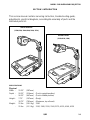
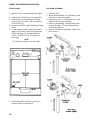
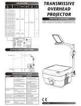
3M 2100 is a high-quality overhead projector that offers various features to enhance your presentations. With its powerful 275-watt lamp, it delivers bright and clear projections, even in well-lit rooms. The projector's versatile projection head allows for easy adjustment of the image size and focus, ensuring optimal viewing for your audience. Additionally, the color tuning knob enables fine-tuning of the projected image, removing any unwanted color casts and providing accurate color reproduction.
3M 2100 is a high-quality overhead projector that offers various features to enhance your presentations. With its powerful 275-watt lamp, it delivers bright and clear projections, even in well-lit rooms. The projector's versatile projection head allows for easy adjustment of the image size and focus, ensuring optimal viewing for your audience. Additionally, the color tuning knob enables fine-tuning of the projected image, removing any unwanted color casts and providing accurate color reproduction.


-
 1
1
-
 2
2
-
 3
3
-
 4
4
-
 5
5
-
 6
6
-
 7
7
-
 8
8
-
 9
9
-
 10
10
-
 11
11
-
 12
12
-
 13
13
-
 14
14
-
 15
15
-
 16
16
-
 17
17
-
 18
18
-
 19
19
-
 20
20
-
 21
21
-
 22
22
-
 23
23
-
 24
24
-
 25
25
-
 26
26
-
 27
27
-
 28
28
-
 29
29
-
 30
30


3M 2100 is a high-quality overhead projector that offers various features to enhance your presentations. With its powerful 275-watt lamp, it delivers bright and clear projections, even in well-lit rooms. The projector's versatile projection head allows for easy adjustment of the image size and focus, ensuring optimal viewing for your audience. Additionally, the color tuning knob enables fine-tuning of the projected image, removing any unwanted color casts and providing accurate color reproduction.
Ask a question and I''ll find the answer in the document
Finding information in a document is now easier with AI
Related papers
Other documents
-
 4MODERNHOME T107 User manual
-
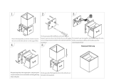 INHDBOX LED Aluminum Waterproof Wall Lamp,12W 100-277V 3000K Adjustable Outdoor Wall Light Warm Light 3.94",Non-Dimmable (Black-Warm Light) Installation guide
-
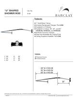 Barclay Products 4140-48-CP Specification
-
Barco Ultra wide fixed lens EN47 Installation guide
-
Barco Ultra wide fixed lens EN47 Installation guide
-
Kodak Carousel S-AV 2050 Maintenance Manual
-
-
Dukane 28A663 User manual
-
Infocus 410P User manual
-
 Acco Europe 20421/1 Operating instructions


