8
11/1/2016 - DOCUMENT NUMBER: 10-0311
© 2016 AEM Performance Electronics
30-0311 - OBD-II
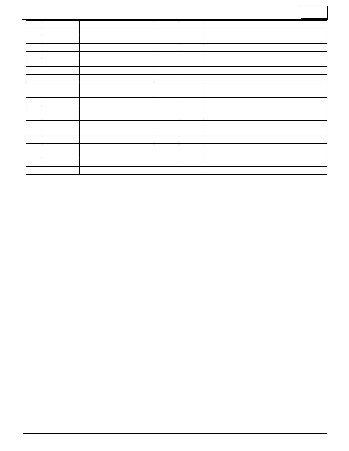
-Negative = Lean / +Positive = Rich
-Negative = Lean / +Positive = Rich
-Negative = Lean / +Positive = Rich
-Negative = Lean / +Positive = Rich, If $06 is n/
a
-Negative = Lean / +Positive = Rich
-Negative = Lean / +Positive = Rich, If $08 is n/
a
Actual Engine - Percent
Torque
% = ( TPS Voltage / 5.0V ) * 100
Relative throttle position
% = ( (TPS Voltage - Closed TPS Voltage) / 5.0V
) * 100
FAQ / Troubleshooting
I installed my gauge correctly and the display just shows dashes, "----", or keeps going dark, turning the display
off
o Make sure the OBD-II connector is firmly seated into the car's OBD-II port
o Make sure that your car is fitted with an OEM ECU that supports OBD-II over CAN. This is federally mandated for US
vehicles 2008 and newer, however some older cars may have adopted CAN in earlier model years.
o Most vehicles require the key to be in the 'Run' position such that the OEM ECU is powered on and sending OBD-II
data to the gauge.
o The engine must be started and remain running for the gauge to remain "awake."
o Make sure that the AEM OBD-II gauge is the only OBD-II device/scanner that is connected to the vehicle. Multiple
devices on the bus may cause unexpected functionality.
This manual says that a PID is supported but I can't find it when I scroll through the PID list using the PAGE
button.
Your vehicle may not support every PID that is supported by the AEM OBD-II gauge. Upon power-up, the gauge will query
the vehicle for a list of the available PIDs and display the ones which are supported by the gauge. If the PID is not listed
when scrolling through the list using the PAGE button, then the PID is not supported by your vehicle.
My gauge is displaying DTC (Diagnostic Trouble Codes) but I don't know what they mean.
DTC codes have a standardized format; one letter followed by four numbers, e.g. P0030. You may look up their meaning
by referring to your vehicle's factory service manual or using an online resource such as www.obd-codes.com.
My check engine light is on or my other OBD-II scanner says I have a DTC but the gauge reports "nonE" when I
depress the DTC button.
The OBD-II specification sets forth a distinction between "pending" trouble codes and "stored" trouble codes. The AEM
OBD-II gauge will only display "stored" trouble codes. Please refer to your factory service manual or SAE specification for
further information on "pending" codes. The gauge's DTC clear function will, however, reset ALL codes, both pending and
stored.
I followed the procedure to clear my DTC, the gauge said "CLr" but the light remains on and I still have codes.
Some vehicles require the engine be off to clear codes. In this case, start the engine to wake up the gauge, turn off the
engine but return the key to the "run" position immediately so the ECU is on and transmitting CAN data to the gauge.
Immediately after, follow the procedure to clear the DTCs before the gauge goes to sleep. Alternatively, if you don't wish
to start the engine, you may unplug the gauge from the OBD port and plug it back in to wake up the gauge, turn the key to
Run, and then follow the procedure to clear DTCs.
My gauge seems to take a long time to turn on/off.