Page is loading ...

ISTRUZIONI D’USO E DI INSTALLAZIONE
INSTALLATION AND USER’S MANUAL
INSTRUCTIONS D’UTILISATION ET D’INSTALLATION
INSTALLATIONS-UND GEBRAUCHSANLEITUNG
INSTRUCCIONES DE USO Y DE INSTALACION
GEBRUIKS- EN INSTALLATIEAANWIJZINGEN
D812218 00100_01 27-03-15
AUTOMATISMO ELETTROMECCANICO PER BARRIERA VEICOLARE
ELECTROMECHANICAL CONTROL DEVICE FOR VEHICULAR BARRIERS
AUTOMATISME ELECTROMECANIQUE POUR BARRIERE POUR VÉHICULES
ELEKTROMECHANISCHER ANTRIEB FÜR FAHRZEUGSCHRANKEN
AUTOMATISMOS ELECTROMECANICOS PARA BARRÉRAS VEHICULAR
ELEKTROMECHANISCH AUTOMATISERINGSSYSTEEM VOOR SLAGBOOM
Attenzione! Leggere attentamente le “Avvertenze” all’interno! Caution! Read “Warnings” inside carefully! Attention! Veuillez lire attentivement les Avertissements qui se trouvent à l’intérieur!
Achtung! Bitte lesen Sie aufmerksam die „Hinweise“ im Inneren! ¡Atención¡ Leer atentamente las “Advertencias”en el interior! Let op! Lees de “Waarschuwingen” aan de binnenkant zorgvuldig!
8
027908 482082
MICHELANGELO BT A 60
MICHELANGELO BT A 80

Con scavo di fondazione:
With foundation plate embedded in ground:
Avec tranchée de fondation:
Mit Fundamentgraben:
Con excavación de cimentación:
Met uitgraving:
Non in dotazione /
Not supplied /
Ne sont pas fournis /
Nicht im lieferumfang
/
No asignadas en el
equipamiento base
/
Niet meegeleverd
*
Con tiranti:
With anchor bolts:
Avec tirants:
Mit Ankerbolzen:
Con tirantes:
Met spankabels:
1
2
3
5
4
3
B1
B2
A
V
V
12
35
*
1
2
INSTALLAZIONE VELOCE-QUICK INSTALLATION-INSTALLATION RAPIDE
SCHNELLINSTALLATION-INSTALACIÓN RÁPIDA - SNELLE INSTALLATIE
S
F
Ft
CF
T
CS
A
IM
QR
AL
RMM
Fr
From825
to 841mm
2 x 0,75
3 x 1,5
3 x 0,75
4m (ML MCL40)
6m MICHELANGELO BT A 60
8m MICHELANGELO BT A 80
2 - MICHELANGELO BT A
D812218 00100_01

ENGLISH FRANÇAIS ESPAÑOL
NEDERLANDS
DEUTSCHITALIANO
D
E
C
Per montaggio aste fare riferimento ai manuali
See manuals for boom assembly
Pour monter les barres consultez les manuels
Bitte nehmen Sie für die Montage der Stange auf die Handbücher
Bezug
Para montar los mástiles consultar los manuales
Raadpleeg de handleidingen voor de montage van de bomen
Apertura e chiusura coperchio e portina, Opening and closing cover and door, Ouverture et fermeture du couvercle et portillon,
Önung und Schließung Abdeckung und kleine Tür, Apertura y cierre de la tapa y de la portezuela, Opening en sluiting deksel en klepje.
1
3
2
1
2
2
1
2
3
2
3
MICHELANGELO BT A- 3
D812218 00100_01

F1
L: Lunghezza utile asta.
L: Working boom length.
L: Longueur utile de la barre.
L: Nutzlänge der Schranke.
L: Longitud útil mástil.
L: Nuttige lengte slagboom.
*
1
(above boom only)
(uniquement sur la barre)
(nur über der Schranke)
(sólo sobre el mástil)
(alleen boven de slagboom)
*
2
(below boom only)
(uniquement sous la barre)
(nur unter der Schranke)
(sólo debajo el mástil)
(alleen onder de slagboom)
L
35 cm
Accessori MICHELANGELO: lunghezza utile asta e bilanciamento. / MICHELANGELO Accessories: working length of boom and balancing. / Accessoires MICHELANGELO: longueur utile de la barre et équilibrage. /
MICHELANGELO Zubehör: Nutzlänge Schranke und Auswuchtung. / Accesorios MICHELANGELO: longitud útil mástil y balance. / Accessoires MICHELANGELO: nuttige lengte slagboom en balancering.
SB + SB + SB + SB + SB + SB + SB
PCA N (solo sopra l’asta)*
1
+
PCA N
+ PCA N
+
PCA N
+ PCA N
+
PCA N
+
PCA N
+ PCA N + PCA N
+
PCA N
+ PCA
N
+
PCA N
+ PCA
N
+
PCA N
+ PCA N + PCA N
PCA N (solo sotto l’asta)*
2
+
PCA N
+ PCA N
+
PCA N
+ PCA N
KIT MCL LIGHT + LIGHT + LIGHT + LIGHT + LIGHT + LIGHT + LIGHT + LIGHT
GA AQ AT / GAMA AQ AT
+ GA/
GAMA
+ GA/
GAMA
+ GA/
GAMA
+ GA/
GAMA
+ GA/
GAMA
+ GA/
GAMA
+ GA/
GAMA
+ GA/
GAMA
+ GA/
GAMA
+ GA/
GAMA
+ GA/
GAMA
BIR + BIR + BIR + BIR + BIR + BIR + BIR
ML MCL40
+ AT704
A
MIN L 2,8 2,8 2,9 3,2 3,3 3,4 3,5 3,6 3,5 3,7 3,9 3 3 3,1 3,5 3,5 3,6 3,8 3,8
MAX L 3 3,1 3,1 3,4 3,5 3,6 3,7 3,9 3,8 3,9 4 3,2 3,2 3,3 3,7 3,8 3,9 4 4
B
MIN L 3,4 2,1 2,1 2,2 2,4 2,4 2,5 2,6 2,7 2,6 2,7 2,8 2,3 2,3 2,4 2,6 2,7 2,8 2,8 2,9 3
MAX L 4 2,5 2,6 2,6 2,9 2,9 3 3,1 3,3 3,2 3,3 3,5 2,7 2,7 2,8 3,1 3,2 3,3 3,4 3,5 3,6
C
MIN L 2,6 1,6 1,6 1,7 1,9 2 2 2,1 2,2 2,1 2,2 2,3 1,8 1,8 1,9 2,1 2,1 2,2 2,3 2,3 2,4
MAX L 3,2 2,1 2,1 2,2 2,4 2,5 2,5 2,6 2,8 2,7 2,8 2,9 2,3 2,3 2,4 2,7 2,7 2,8 2,9 3 3,1
ML MCL40
+
AQ6
A
MIN L 3 3,1 3,2 3,6 3,6 3,8 3,9 3,3 3,3 3,4 3,9 3,9
MAX L 3,3 3,3 3,4 3,8 3,9 4 4 3,5 3,5 3,7 4 4
B
MIN L 3,8 2,3 2,3 2,4 2,6 2,7 2,8 2,9 3,1 3 3,1 3,3 2,5 2,5 2,6 2,9 3 3,1 3,3 3,3 3,3
MAX L 4 2,7 2,8 2,9 3,2 3,3 3,4 3,5 3,7 3,6 3,8 4 2,9 3 3,1 3,5 3,6 3,7 3,9 4 4
C
MIN L 3 1,8 1,8 1,9 2,1 2,2 2,3 2,3 2,4 2,3 2,5 2,6 2 2 2,1 2,3 2,4 2,5 2,6 2,7 2,8
MAX L 3,8 2,3 2,3 2,4 2,7 2,8 2,9 3 3,1 3 3,2 3,4 2,5 2,5 2,6 3 3 3,2 3,3 3,4 3,6
MCL 60 +
AQ6
A
MIN L 5,3 4,2 4,3 4,4 4,9 5 5,4 5,3 5,4 5,4 5,5 5,6 4,5 4,6 4,7 5,3 5,4 5,4 5,5 5,6 5,7
MAX L 6 4,7 4,8 4,9 5,5 5,6 5,9 6 6 6 6 6 5 5,1 5,2 5,9 6 6 6 6 6
B
MIN L 4,8 3,2 3,2 3,3 3,9 4 4,3 4,2 4,4 4,3 4,4 4,5 3,6 3,7 3,8 4,3 4,4 4,5 4,4 4,5 4,8
MAX L 6 4 4,1 4,2 4,9 4,9 5,3 5,3 5,5 5,5 5,5 5,5 4,4 4,4 4,5 5,3 5,3 5,5 5,5 5,6 5,9
MCL 60 +
AT704 +
AT502
A
MIN L 5,2 4,5 4,5 4,7 4,9 5,1 5,2 5,2 5,3 4,7 4,8 5 5,2 5,3 5,4
MAX L 6 5,2 5,3 5,5 5,7 5,9 5,9 6 6 5,5 5,6 5,8 6 6 6
B
MIN L 3,8 2,8 2,9 3,1 3,1 3,4 3,4 3,5 3,6 3,3 3,4 4,2 3,8 3,8 3,9
MAX L 5,1 4,1 4,2 4,5 4,5 5 4,9 5 5,1 4,5 4,6 5 5,1 5,1 5,1
MCL 60 +
AT706
A
MIN L 5,3 3,6 3,7 3,8 4,2 4,3 4,4 4,5 4,7 4,6 4,8 5 3,8 3,9 4 4,4 4,5 4,6 4,8 4,9 5,1
MAX L 6 4,1 4,2 4,3 4,7 4,8 4,9 5,1 5,3 5,2 5,4 5,6 4,3 4,4 4,5 4,9 5 5,2 5,4 5,5 5,7
B
MIN L 4,2 2,9 2,9 3 3,3 3,3 3,5 3,6 3,7 3,6 3,8 3,9 3 3,1 3,2 3,5 3,6 3,7 3,8 3,9 4
MAX L 5,3 3,6 3,7 3,8 4,2 4,2 4,4 4,5 4,7 4,6 4,8 5 3,8 3,9 4 4,4 4,5 4,6 4,8 4,9 5,1
4 - MICHELANGELO BT A
D812218 00100_01

ENGLISH FRANÇAIS ESPAÑOL
NEDERLANDS
DEUTSCHITALIANO
G2
1
4
Bilanciamento Asta, Boom balancing, Equilibrage de la barre, Auswuchtung der Stange, Balance del mástil, Balancering stang.
2
0°
45°
F3
3
5
+ 45 °
- 45 °
90 °
0 °
+ 45 °
- 45 °
45° OK
L: Lunghezza utile asta.
L: Working boom length.
L: Longueur utile de la barre.
L: Nutzlänge der Schranke.
L: Longitud útil mástil.
L: Nuttige lengte slagboom.
*
1
(above boom only)
(uniquement sur la barre)
(nur über der Schranke)
(sólo sobre el mástil)
(alleen boven de slagboom)
*
2
(below boom only)
(uniquement sous la barre)
(nur unter der Schranke)
(sólo debajo el mástil)
(alleen onder de slagboom)
L
35 cm
Accessori MICHELANGELO 80: lunghezza utile asta e bilanciamento. / MICHELANGELO 80 Accessories: working length of boom and balancing. / Accessoires MICHELANGELO 80: longueur utile de la barre et équilibrage. /
MICHELANGELO 80 Zubehör: Nutzlänge Schranke und Auswuchtung. / Accesorios MICHELANGELO 80: longitud útil mástil y balance. / Accessoires MICHELANGELO 80: nuttige lengte slagboom en balancering.
SB + SB + SB + SB + SB + SB + SB
PCA N (solo sopra l’asta)*
1
+
PCA N
+ PCA N
+
PCA N
+ PCA N
+
PCA N
+
PCA N
+ PCA N + PCA N
+
PCA N
+ PCA N
+
PCA N
+ PCA N
+
PCA N
+ PCA N + PCA N
PCA N (solo sotto l’asta)*
2
+
PCA N
+ PCA N
+
PCA N
+ PCA N
KIT MCL LIGHT + LIGHT + LIGHT + LIGHT + LIGHT + LIGHT + LIGHT + LIGHT
GA/GAMA AQ AT
+ GA/
GAMA
+ GA/
GAMA
+ GA/
GAMA
+ GA/
GAMA
+ GA/
GAMA
+ GA/
GAMA
+ GA/
GAMA
+ GA/
GAMA
+ GA/
GAMA
+ GA/
GAMA
+ GA/
GAMA
BIR + BIR + BIR + BIR + BIR + BIR + BIR
MCL 80 +
AT706
A
MIN L 5,4 5,5 5,6 5,6 5,6 5,8
MAX L 5,6 5,7 5,8 5,8 5,9 6
MCL 80+
AT704+
AT504
A
MIN L 7,9 6,4 6,5 6,8 7,1 7,4 7,1 7,5 7,9 6,9 7 7,3 7,6 7,8 7,9
MAX L 8 7,1 7,2 7,5 7,8 8 7,6 8 8 7,3 7,4 7,8 8 8 8
F2
MICHELANGELO BT A- 5
D812218 00100_01

Connettore programmatore palmare,
Palmtop programmer connector,
Connecteur programmateur de poche,
Steckverbinder Palmtop-Programmierer,
Conector del programador de bolsillo,
Connector programmeerbare palmtop.
Connettore scheda opzionale / Optional board connector,
Connecteur carte facultative / Steckverbinder Zusatzkarte,
Conector de la tarjeta opcional / Connector optionele kaart.
Sec transf
Sec transf
2. Transf
Seg transf
Tweede transf
Sec trasf
Display + tasti programmazione / Display plus programming keys,
Acheur et touches de programmation / Display und Programmierungstasten,
Pantalla mas botones de programacion / Display meerdere toetsen programmeur.
Connettore encoder
Encoder connector
Connecteur encodeur
Steckverbindung Encoder
Conector Encoder
Connector encoder
F3 1,25A T
10 11 20 21 26 27 41 42 43 50 51 52 60 61 62 70 71 72 73 74 75
M1
+
-
Motore / Motor / moteur
Motor /Eindaanslag/Encoder
AUX 3
(MAX 24V 1A)
AUX
24V -
+ REF SW
RIFC
RIFO
24V +
24 VSafe+
COM
IC 1
IC 2
NO
NC
NC
NO
Alimentazione accessori
Accessories power supply
Alimentation des accessoires
Stromversorgung Zubehör
Alimentación accesorios
Voeding accessoires
Collegamento gruppo necorsa
Limit switch assembly connection
Connexion groupe n de course
Anschluss Endschaltergruppe
Conexión grupo nal de carrera
Verbinding groep eindaanslagen
Comandi / Commands
Commandes/Bedienelemente
Mandos/ Commando's
SAFE 1
STOP
COM
FAULT 1
SAFE 2
FAULT 2
NC
NC
NC
Sicurezze
Safety devices
Sécurités
Sicherheitsvorrichtungen
Dispositivos de seguridad
Veiligheden
S1
S2
S3
+
-
OK
!
AUX 0 - 24V
(MAX 1A)
24V
2
3
4
1
G
H
Cablaggio Trasformatore, Transformer wiring, Câblage du transformateur,
Verkabelung Transformator, Cableado Transformador, Bekabeling Transformator.
Ponte raddrizzatore / Rectier bridge
Pont redresseur / Gleichrichterbrücke
Puente recticador / Gelijkrichterbrug
6 - MICHELANGELO BT A
D812218 00100_01

ENGLISH FRANÇAIS ESPAÑOL
NEDERLANDS
DEUTSCHITALIANO
1
2
3
4
Connessione A Sistema Gestione Parcheggi, Connection To Car-park Management System, Connexion Au Système De Gestion Des Parkings,
Anschluss An Das Parkplatzbewirtschaftungssystem, Conexion Al Sistema De Gestion De Aparcamientos, Erbinding Met Beheersysteem parkeer-
plaatsen
24V
Collegamento di 1 coppia di fotocellule non vericate,
Connection of 1 pair of non-tested photocells,
Connexion 1 paire photocellules no vériées,
Anschluss von einem Paar nicht überprüften Fotozellen,
Conexión de 1 par fotocélulas no comprobadas,
Aansluiting van 1 paar fotocellen anders dan “trusted device”.
2
1
TX1
2
1
RX1
4
5
3
SAFE 1 = 0
50 51
70 72
AUX 0 = 0
AUX 0 = 1
AUX 0 = 2
AUX 0 = 3
AUX 0 = 4
AUX 0 = 5
AUX 0 = 7
AUX 0 = 8
AUX 0 = 9
AUX 0 = 10
AUX 0 = 12
AUX 0 = 6
!
24V
20 21
AUX0 - 24V
(MAX 1A)
20 21
24V
26
27
26 27
AUX 3 = 0
AUX 3 = 2
AUX 3 = 3
AUX 3 = 4
AUX 3 = 5
AUX 3 = 6
AUX 3 = 7
AUX 3 = 8
AUX 3 = 9
AUX 3 = 10
AUX 3 = 12
AUX 3 = 12 AUX 3 = 12
AUX 3 = 1
AUX 3 = 1
24 V
SCA
26 27
26 27 50 51
L
I
MICHELANGELO BT A- 7
D812218 00100_01

ENGLISH FRANÇAIS ESPAÑOL
NEDERLANDS
DEUTSCHITALIANO
SIMPLIFIED MENU (FIG .1)
Dir
ITA
fra
deu
eng
esp
ar
sr
ac
Sc
Ind
AR
preset
O 01
sr
ac
sc
ind
:
semiautomatic
operation,
residential
: automatic
operation,
commercial
:
semiautomatic
operation,
commercial
:dead man
operation
lh:
right barrier
rh:
lh
rh
left barrier
:
automatic
operation,
residential
release
end
desidered button
e
hidden button
re otes
x1
0---
10--
150- 1520 ok
Exit Menù
Conrm/Switch on display
Scroll up
Scroll down
language
***
PRESET DEFAULT
ar sr ac sc ind
PARAMETERS
Automatic closing time [s]
10 10 10 5 5 5
LOGIC
Automatic Closing Time 1 1 0 1 0 0
Step-by-step movement 1 1 0 1 0 0
Pre-alarm 0 0 0 1 1 0
Deadman 0 0 0 0 0 1
Block pulses during opening 1 0 0 1 1 0
MICHELANGELO BT A- 9
D812218 00100_01

1
AA
2
3
4
19
19
Montaggio Asta Destra, Assembly of right boom, Montage de la barre droite,
Rechte Montage der Stange, Montaje mástil derecho, Montage rechterstang.
Inversione direzione di aperura: 1
Open in other direction: 1
Inversion direction de l’ouverture: 1
Richtungsumkehrung Önung: 1
Inversión dirección de apertura: 1
Openingsrichting omdraaien: 1
Smontare il gruppo molla.
Remove the spring assembly.
Démonter le groupe ressort.
Die Feder-Baugruppe ausbauen.
Desmontar el grupo muelle.
De groep veer demonteren.
Assicurarsi che la molla non sia in tensione, e l’asta non sia montata.
Make sure the spring is not under tension and the boom is not tted.
Vériez si le ressort n’est pas en tension et si la tige n’est pas montée.
Sicherstellen, dass die Feder nicht gespannt und die Stange nicht montiertist.
Asegurarse de que el muelle no esté tensado y de que el mástil no esté montado.
Controleren of de veer niet onder spanning staat, en de stang niet gemonteerd is.
Inversione direzione di aperura: 0
Open in other direction: 0
Inversion direction de l’ouverture: 0
Richtungsumkehrung Önung: 0
Inversión dirección de apertura: 0
Openingsrichting omdraaien: 0
14 - MICHELANGELO BT A
D812218 00100_01

Rimontare il gruppo molla a destra, Ret the right-hand spring assembly,
Remontez le groupe ressort à droite, Die Baugruppe neu montieren, Feder rechts,
Volver a montar el grupo muelle a la derecha, De veergroep opnieuw rechts monteren.
7
8
6
5
9
AB
ENGLISH FRANÇAIS ESPAÑOL
NEDERLANDS
DEUTSCHITALIANO
MICHELANGELO BT A- 15
D812218 00100_01

1
2
3
2 mm
2 mm
Assicurarsi che la molla non sia in tensione, e l’asta non sia montata.
Make sure the spring is not under tension and the boom is not fitted.
Vériez si le ressort n'est pas en tension et si la tige n'est pas montée.
Sicherstellen, dass die Feder nicht gespannt und die Stange nicht montiertist.
Asegurarse de que el muelle no esté tensado y de que el mástil no esté montado.
Controleren of de veer niet onder spanning staat, en de stang niet gemonteerd is.
AC
19
16 - MICHELANGELO BT A
D812218 00100_01

4
5
6
30 mm
AD
19
13
ENGLISH FRANÇAIS ESPAÑOL
NEDERLANDS
DEUTSCHITALIANO
MICHELANGELO BT A- 17
D812218 00100_01

MONTAGGIO LAMPEGGIANTE, FITTING THE FLASHING LIGHT, MONTAGE DU CLIGNOTANT, MONTAGE DER BLINK-
LEUCHTE, MONTAJE DEL INDICADOR PARPADEANTE, MONTAGE FOTOCEL
AE
25
3,9
Per l’installazione del lampeggiante fare riferimento ai manuali del lampeggiante
See the ashing light's manual for instructions on installing the ashing light
Pour monter le clignotant consultez le manuel du clignotant
Bitte nehmen Sie für die Installation der Blinkleuchte auf das Handbuch der Blinkleuchte Bezug
Para instalar el indicador parpadeante consultar el manual del mismo
Raadpleeg de handleiding van het zwaailicht voor de installatie van het zwaailicht
ATTENZIONE! togliere il coperchietto A
PLEASE NOTE! Remove cover A
ATTENTION ! Retirez le couvercle A
ACHTUNG! Entfernen Sie die Abdeckung A
¡ATENCIÓN! Quitar la tapa A
OPGELET! Demonteer het klepje A
ATTENZIONE! fissare il lampeggiante alla barriera con la vite (V1)
PLEASE NOTE! Fasten the ashing light on the barrier using the screw (V1)
ATTENTION ! Fixez le clignotant sur la barrière avec la vis (V1)
ACHTUNG! Befestigen Sie die Blinkleuchte mit der Schraube (V1) an der Schranke
¡ATENCIÓN! Fijar el indicador parpadeante a la barrea con el tornillo (V1)
OPGELET! Bevestig het zwaailicht met de schroef (V1) aan de slagboom
V1
MONTAGGIO FOTOCELLULA, FITTING THE PHOTOCELL , MONTAGE DE LA PHOTOCELLULE, MONTAGE DER FOTOZELLE,
MONTAJE DE LA FOTOCÉLULA, MONTAGE FOTOCEL
AF
Per l’installazione della fotocellula e della fotocellula con supporto colonnina fare riferimento
ai manuali delle fotocellule e ai manuali supporto colonnina
See the photocell's manuals and post mount's manuals for instructions on installing the
photocell and photocell with post mount
Pour monter la photocellule et la photocellule avec colonnette de support consultez le
manuel des photocellules et le manuel de la colonnette de support
Bitte nehmen Sie für die Installation der Fotozelle und der Fotozelle mit Säulenhalterung auf
das Handbuch der Fotozellen und auf das Handbuch der Säulenhalterung Bezug
Para instalar la fotocélula y la fotocélula con soporte columna consultar el manual de las
fotocélulas y el manual del soporte columna
Raadpleeg de handleiding van de fotocellen en de handleiding van de
steunpilaar voor de montage van de fotocel en de fotocel met steunpilaar
ATTENZIONE! togliere il coperchietto A, B o C per installare la fotocellula o il supporto colonnina
Please note! Remove cover A, B or C to install the photocell or post mount
Attention ! Retirez le couvercle A, B ou C pour monter la photocellule ou la colonnette de support
Achtung! Entfernen Sie die Abdeckung A, B oder C für die Installation der Fotozelle oder der Säulenhalterung
¡Atención! Quitar la tapa A, B o C para instalar la fotocélula o el soporte columna
Opgelet! Demonteer het klepje A, B of C voor de installatie van de fotocel of de steunpilaar
ATTENZIONE! fissare la fotocellula alla barriera con la vite qui illustrata (V2)
PLEASE NOTE! Fasten the photocell on the barrier using the screw (V2)
ATTENTION ! Fixez la photocellule sur la barrière avec la vis (V2)
ACHTUNG! Befestigen Sie die Fotozelle mit der Schraube (V2) an der Schranke
¡ATENCIÓN! Fijar la fotocélula a la barrea con el tornillo (V2)
OPGELET! Bevestig de fotocel met de schroef (V2) aan de slagboom
22
2,9
V2
Installazione fotocellula
Installing the photocells
Montage des photocellules
Installation der Fotozelle
Instalación fotocélulas
Installatie fotocellen
Installazione fotocellula
con relativo supporto
Installing the photocell with post mount
Montage de la photocellule avec colonnette de support
Installation der Fotozelle mit Säulenhalterung
Instalación fotocélula con soporte columna
Installatie fotocel met steunpilaar
V2
A
B
C
Installazione lampeggiante
Installing the ashing light
Installation du clignotant
Installation der Blinkleuchte
Instalación del indicador parpadeante
Installatie zwaailicht
V2
A
C
18 - MICHELANGELO BT A
D812218 00100_01

2
4 5
3
Montaggio rilevatore di masse metalliche, Fitting the metal object detector, Montage du
détecteur de masses métalliques, Montage des Metallmassenmelders, Montaje del detector de
masas metálicas, Montage detector metalen massa's
AG
*
8
4
Non in dotazione /
Not supplied / Ne sont pas fournis /
Nicht im lieferumfang
/
No asignadas en el equipamiento base
/
Niet meegeleverd
*
A
B
1
2
2
1
1
2
3
2
3
2
3
1
2
3
ENGLISH FRANÇAIS ESPAÑOL
NEDERLANDS
DEUTSCHITALIANO
MICHELANGELO BT A- 19
D812218 00100_01

E
M
SCHEDA DI ESPANSIONE
EXPANSION BOARD
CARTE D’EXPANSION
ERWEITERUNGSKARTE
TARJETA DE EXPANSIÓN
UITBREIDINGSKAART
UNIDA
Programmeerbare Universele Palmtop
B EBA U-LINK 485
50 51 52
CC2
70 71 72 73 74 75
SAFE 1 = 1
SAFE 2 = 7
SAFE 2 = 7
50 51 52 6160
TX1 RX1
CC1
62 63 64 65 70 71 72 73 74 75
START
STOP
MAX 250m
PER IL COLLEGAMENTO DI PIÙ FOTOCELLULE FARE RIFERIMENTO ALLA FIG. P - TO CONNECT SEVERAL PHOTOCELLS, REFER TO FIG. P
POUR BRANCHER PLUSIEURS PHOTOCELLULES CONSULTEZ LA FIG. P - BITTE NEHMEN SIE FÜR DEN ANSCHLUSS MEHRERER FOTOZELLEN AUF FIG. P BEZUG.
PARA LA CONEXIÓN DE VARIAS FOTOCÉLULAS CONSULTAR LA FIG. P - VOOR HET VERBINDEN VAN MEERDERE FOTOCELLEN ZIE FIG. P
B EBA U-LINK 485
F3 1,25A T
10 11 20 21 26 27 41 42 43 50 51 52 60 61 62 70 71 72 73 74 75
S1
S2
S3
+
-
OK
F3 1,25A T
10 11 20 21 26 27 41 42 43 50 51 52 60 61 62 70 71 72 73 74 75
S1
S2
S3
+
-
OK
8888
N
iNDIRIZZO=0
address=0
adresse=0
adresse=0
direccion=0
modo seriale=3
serial mode=3
mode serie=3
serieller modus=3
modo seria=3
iNDIRIZZO=0
address=0
adresse=0
adresse=0
direccion=0
modo seriale=2
serial mode=2
mode serie=2
serieller modus=2
modo seria=2
O
ON ON
OFF OFF
S1
S2
S3
+
-
OK
ON ON
OFF OFF
S1
S2
S3
+
-
OK
70 71
COM
STOP
S1
S2
S3
+
-
OK
S1
S2
S3
+
-
OK
8888 rst8
8888
. ...
1 2 3 4
65
!
<3s
+
MASTER SLAVE
20 - MICHELANGELO BT A
D812218 00100_01

P
Numero massimo di dispositivi verifcati: 6 (ma non più di 4 per tipo),
Maximum number of tested devices: 6 (but no more than 4 per type),
Nombre maximum dispositif vérifés: 6 (mais pas plus de 4 par type),
Max. Anzahl der überprüften Geräte: 6 (jedoch nicht mehr als 4 je Typ),
Número máximo dispositivos comprobados: 6 (pero no más de 4 por tipo),
Maximumaantal “trusted devices”: 6 (maar niet meer dan 4 per type)
50
51
52
70
71
72
73
74 75
24V -
24V +
24 VSafe+
COM
SAFE 1
SAFE 2
STOP
FAULT 1
FAULT 2
NC
NC
NC
1-S
2-S
3-S 4-S 5-S 6-S
(SCS-MA)
SAFE 1
1
2
1
2
3
4
5
51
TX1 RX1
Bar 1
1
2
3
4
5
6
1
2
1
2
3
4
5
52
50
TX1 RX1
1
2
1
2
3
4
5
TX1 RX1
1
2
1
2
3
4
5
TX2 RX2
1
2
1
2
3
4
5
TX1 RX1
1
2
1
2
3
4
5
TX2 RX2
1
2
1
2
3
4
5
TX3 RX3
1
2
1
2
3
4
5
TX1
RX1
1
2
1
2
3
4
5
TX2
RX2
1
2
1
2
3
4
5
TX3
RX3
1
2
1
2
3
4
5
TX4
RX4
Bar 1
1
2
3
4
5
Bar 2
1
2
3
4
5
Bar 1
1
2
3
4
5
Bar 2
1
2
3
4
5
Bar 3
1
2
3
4
5
Bar 1
1
2
3
4
5
Bar 2
1
2
3
4
5
Bar 4
1
2
3
4
5
Bar 3
1
2
3
4
5
Bar 1
1
2
3
4
5
6
6
6
6
6
6
6
6
6
6
1
2
1
2
3
4
5
TX1 RX1
Bar 1
1
2
3
4
5
6
1
2
1
2
3
4
5
TX1 RX1
1
2
1
2
3
4
5
TX1 RX1
1
2
1
2
3
4
5
TX2 RX2
1
2
1
2
3
4
5
TX1 RX1
1
2
1
2
3
4
5
TX2 RX2
1
2
1
2
3
4
5
TX3 RX3
1
2
1
2
3
4
5
TX1
RX1
1
2
1
2
3
4
5
TX2
RX2
1
2
1
2
3
4
5
TX3
RX3
1
2
1
2
3
4
5
TX4
RX4
Bar 1
1
2
3
4
5
Bar 2
1
2
3
4
5
Bar 1
1
2
3
4
5
Bar 2
1
2
3
4
5
Bar 3
1
2
3
4
5
Bar 1
1
2
3
4
5
Bar 2
1
2
3
4
5
Bar 4
1
2
3
4
5
Bar 3
1
2
3
4
5
Bar 1
1
2
3
4
5
6
6
6
6
6
6
6
6
6
6
SAFE1 = 1,3,5
SAFE1 = 0,2,4
SAFE1 = 7
SAFE1 = 8
1 PHOT / 1 PHOT OP / 1 PHOT CL
1 PHOT / 1 PHOT OP / 1 PHOT CL
2 PHOT / 2 PHOT OP / 2 PHOT CL
3 PHOT / 3 PHOT OP / 3 PHOT CL
4 PHOT / 4 PHOT OP / 4 PHOT CL
BAR 8K2
1 BAR
1 BAR
2 BAR
3 BAR
4 BAR
50
52
50
52
50
52
50
52
50
52
50
52
50
52
50
52
50
52
50
51
50
51
50
51
50
51
50
51
50
51
50
51
50
51
50
51
50
51
50
51
50
70
72
70
72
73
70
70
70
70
70
70
72
72
72
73
2-S
1-S
3-S
73
2-S
1-S
3-S
5-S
4-S
6-S
73
51
51
50
51
50
51
50
51
50
51
50
51
50
51
50
51
50
51
50
51
50
52
52
52
52
52 52
52
52
52 52
72
70
72
70
73
72
70
51
50
70
73
72
70
4-S
5-S
6-S
70
73
72
70
1-S
2-S
4-S
5-S
3-S
70
73
6-S
70
72
8,2Kohm 5%
SAFETY EDGE
SAFETY EDGE
1
SAFE1 = 6
3
2
5
4
SAFE 2
1
2
1
2
3
4
5
51
TX1 RX1
Bar 1
1
2
3
4
5
6
1
2
1
2
3
4
5
52
50
TX1 RX1
1
2
1
2
3
4
5
TX1 RX1
1
2
1
2
3
4
5
TX2 RX2
1
2
1
2
3
4
5
TX1 RX1
1
2
1
2
3
4
5
TX2 RX2
1
2
1
2
3
4
5
TX3 RX3
1
2
1
2
3
4
5
TX1
RX1
1
2
1
2
3
4
5
TX2
RX2
1
2
1
2
3
4
5
TX3
RX3
1
2
1
2
3
4
5
TX4
RX4
Bar 1
1
2
3
4
5
Bar 2
1
2
3
4
5
Bar 1
1
2
3
4
5
Bar 2
1
2
3
4
5
Bar 3
1
2
3
4
5
Bar 1
1
2
3
4
5
Bar 2
1
2
3
4
5
Bar 4
1
2
3
4
5
Bar 3
1
2
3
4
5
Bar 1
1
2
3
4
5
6
6
6
6
6
6
6
6
6
6
1
2
1
2
3
4
5
TX1 RX1
Bar 1
1
2
3
4
5
6
1
2
1
2
3
4
5
TX1 RX1
1
2
1
2
3
4
5
TX1 RX1
1
2
1
2
3
4
5
TX2 RX2
1
2
1
2
3
4
5
TX1 RX1
1
2
1
2
3
4
5
TX2 RX2
1
2
1
2
3
4
5
TX3 RX3
1
2
1
2
3
4
5
TX1
RX1
1
2
1
2
3
4
5
TX2
RX2
1
2
1
2
3
4
5
TX3
RX3
1
2
1
2
3
4
5
TX4
RX4
Bar 1
1
2
3
4
5
Bar 2
1
2
3
4
5
Bar 1
1
2
3
4
5
Bar 2
1
2
3
4
5
Bar 3
1
2
3
4
5
Bar 1
1
2
3
4
5
Bar 2
1
2
3
4
5
Bar 4
1
2
3
4
5
Bar 3
1
2
3
4
5
Bar 1
1
2
3
4
5
6
6
6
6
6
6
6
6
6
6
SAFe 2= 1,3,5
SAFe 2 = 0,2,4
SAFe 2 = 6
SAFe 2 = 7
SAFe 2 = 8
1 PHOT / 1 PHOT OP / 1 PHOT CL
1 PHOT / 1 PHOT OP / 1 PHOT CL
2 PHOT / 2 PHOT OP / 2 PHOT CL
3 PHOT / 3 PHOT OP / 3 PHOT CL
4 PHOT / 4 PHOT OP / 4 PHOT CL
BAR 8K2
1 BAR
1 BAR
2 BAR
3 BAR
4 BAR
50
52
50
52
50
52
50
52
50
52
50
52
50
52
50
52
50
52
50
51
50
51
50
51
50
51
50
51
50
51
50
51
50
51
50
51
50
51
50
51
50
70
74
70
74
75
70
70
70
70
70
70
74
74
74
75
2-S
1-S
3-S
75
2-S
1-S
3-S
5-S
4-S
6-S
75
51
51
50
51
50
51
50
51
50
51
50
51
50
51
50
51
50
51
50
51
50
52
52
52
52
52 52
52
52
52 52
74
70
74
70
75
74
70
51
50
70
75
74
70
4-S
5-S
6-S
70
75
74
70
1-S
2-S
4-S
5-S
3-S
70
75
6-S
70
74
8,2Kohm 5%
SAFETY EDGE
SAFETY EDGE
1 3
2 4
5
TEST OFFTEST ON
TEST OFFTEST ON
ENGLISH FRANÇAIS ESPAÑOL
NEDERLANDS
DEUTSCHITALIANO
MICHELANGELO BT A- 21
D812218 00100_01

ACCESS MENUS Fig. 2
Exit Menù
Conrm/Switch on display
Scroll up
Scroll down
See PARAMETERS MENU
See LOGIC MENU
See RADIO MENU
add. start
hidden butt
hidden butt
release
release
desired button
desired button
Add. 2ch
erase 64
language
stat
-
+
-
+
OK
vers
bft . . .
+/-
OK
0000
+/-
+/-
n. cycles
OK
OK
password
0---
10--
150- 1520 prg
00
-
+
err
+/-
n. remotes
List of last 30 errors
Control unit
software version
No total
manoeuvres(in hundreds)
No radio control
devices memorised
ALT follow the user guide
x2
0---
10--
150- 1520 ok
01.33
02.01
........
30.15
ENGLISH
Diagnostics
code
DESCRIPTION NOTES
STRE
START E external start input activated
STRI
START I internal start input activated
OPEN
OPEN input activated
CLS
CLOSE input activated
PED
PED pedestrian input activated
TIME
TIMER input activated
STOP
STOP input activated
PHOT
PHOT photocell input activated
PHOP
PHOT OP opening photocell input activated
PHCL
PHOT CL closing photocell input activated
BAR
BAR safety edge input activated
BAR 2
BAR safety edge input activated on slave motor
(opposite leaves connection)
SWC
SWC motor closing limit switch input activated
SWO
SWO motor opening limit switch input activated
ER01
Photocell test failed
Check photocell connection and/or logic settings
ER02
Safety edge test failed
Check safety edge connection and/or logic settings
ER03
Opening photocell test failed
Check photocell connection and/or param-
eter/logic setting
ER04
Closing photocell test failed
Check photocell connection and/or param-
eter/logic setting
ER05
Safety edge test on slave motor failed (opposite leaves con-
nection)
Check safety edge connection and/or param-
eter/logic settings
er06
8k2 safety edge test failed
Check safety edge connection and/or param-
eter/logic settings
ER1x*
Board hardware test error
- Check connections to motor
- Hardware problems with board (contact
technical assistance)
ER2x*
Encoder error
Check the cable, the encoder card and the mo-
tor direction (if necessary) and reset the card
ER3x*
Reverse due to obstacle - Amperostop Check for obstacles in path
ER4x*
Thermal cutout Allow automated device to cool
ER5x*
Communication error with remote devices
Check connection with serial-connected
accessory devices and/or expansion boards
ER7x*
Internal system supervision control error.
Try switching the board o and back on again.
If the problem persists, contact the technical
assistance department.
ErFx*
limit switch error check limit switch connections
* X = 0,1,…,9,A,B,C,D,E,F
MICHELANGELO BT A- 31
D812218 00100_01

INSTALLER WARNINGS
Anything that is not explicitly provided for in the installation ma-
nual is not allowed. The operator’s proper operation can only be
guaranteed if the information given is complied with. The Firm shall
not be answerable for damage caused by failure to comply with the
instructions featured herein.
While we will not alter the product’s essential features, the Firm reserves
the right, at any time, to make those changes deemed opportune to
improve the product from a technical, design or commercial point of
view, and will not be required to update this publication accordingly.
WARNING! Important safety instructions. Carefully read and comply with
all the warnings and instructions that come with the product as incorrect
installation can cause injury to people and animals and damage to property.
The warnings and instructions give important information regarding safety,
installation, use and maintenance. Keep hold of instructions so that you can
attach them to the technical le and keep them handy for future reference.
GENERAL SAFETY
This product has been designed and built solely for the purpose indicated herein.
Uses other than those indicated herein might cause damage to the product and
create a hazard.
- The units making up the machine and its installation must meet the requirements
of the following European Directives, where applicable: 2004/108/EC, 2006/95/
EC, 2006/42/EC, 89/106/EC, 99/05/EC and later amendments. For all countries
outside the EEC, it is advisable to comply with the standards mentioned, in ad-
dition to any national standards in force, to achieve a good level of safety.
- The Manufacturer of this product (hereinafter referred to as the “Firm”) disclaims
all responsibility resulting from improper use or any use other than that for
which the product has been designed, as indicated herein, as well as for failure
to apply Good Practice in the construction of entry systems (doors, gates, etc.)
and for deformation that could occur during use.
- Installation must be carried out by qualied personnel (professional installer,
according to EN 12635), in compliance with Good Practice and current code.
- Before installing the product, make all structural changes required to produce
safety gaps and to provide protection from or isolate all crushing, shearing and
dragging hazard areas and danger zones in general in accordance with the
provisions of standards EN 12604 and 12453 or any local installation standards.
Check that the existing structure meets the necessary strength and stability
requirements.
- Before commencing installation, check the product for damage.
- The Firm is not responsible for failure to apply Good Practice in the construction
and maintenance of the doors, gates, etc. to be motorized, or for deformation
that might occur during use.
- Make sure the stated temperature range is compatible with the site in which the
automated system is due to be installed.
- Do not install this product in an explosive atmosphere: the presence of ammable
fumes or gas constitutes a serious safety hazard.
- Disconnect the electricity supply before performing any work on the system.
Also disconnect buer batteries, if any are connected.
- Before connecting the power supply, make sure the product’s ratings match the
mains ratings and that a suitable residual current circuit breaker and overcurrent
protection device have been installed upline from the electrical system. Have
the automated system’s mains power supply tted with a switch or omnipolar
thermal-magnetic circuit breaker with a contact separation that provide full
disconnection under overvoltage category III conditions.
- Make sure that upline from the mains power supply there is a residual current
circuit breaker that trips at no more than 0.03A as well as any other equipment
required by code.
- Make sure the earth system has been installed correctly: earth all the metal parts
belonging to the entry system (doors, gates, etc.) and all parts of the system
featuring an earth terminal.
- Installation must be carried out using safety devices and controls that meet
standards EN 12978 and EN 12453.
- Impact forces can be reduced by using deformable edges.
- In the event impact forces exceed the values laid down by the relevant standards,
apply electro-sensitive or pressure-sensitive devices.
- Apply all safety devices (photocells, safety edges, etc.) required to keep the
area free of impact, crushing, dragging and shearing hazards. Bear in mind the
standards and directives in force, Good Practice criteria, intended use, the instal-
lation environment, the operating logic of the system and forces generated by
the automated system.
- Apply all signs required by current code to identify hazardous areas (residual
risks). All installations must be visibly identied in compliance with the provisions
of standard EN 13241-1.
- Once installation is complete, apply a nameplate featuring the door/gate’s data.
- This product cannot be installed on leaves incorporating doors (unless the motor
can be activated only when the door is closed).
- If the automated system is installed at a height of less than 2.5 m or is accessible,
the electrical and mechanical parts must be suitably protected.
- Install any xed controls in a position where they will not cause a hazard, away
from moving parts. More specically, hold-to-run controls must be positioned
within direct sight of the part being controlled and, unless they are key operated,
must be installed at a height of at least 1.5 m and in a place where they cannot
be reached by the public.
- Apply at least one warning light (ashing light) in a visible position, and also
attach a Warning sign to the structure.
- Attach a label near the operating device, in a permanent fashion, with informa-
tion on how to operate the automated system’s manual release.
- Make sure that, during operation, mechanical risks are avoided or relevant
protective measures taken and, more specically, that nothing can be banged,
crushed, caught or cut between the part being operated and surrounding parts.
- Once installation is complete, make sure the motor automation settings are
correct and that the safety and release systems are working properly.
- Only use original spare parts for any maintenance or repair work. The Firm dis-
claims all responsibility for the correct operation and safety of the automated
system if parts from other manufacturers are used.
- Do not make any modications to the automated system’s components unless
explicitly authorized by the Firm.
- Instruct the system’s user on what residual risks may be encountered, on the
control systems that have been applied and on how to open the system manu-
ally in an emergency. give the user guide to the end user.
- Dispose of packaging materials (plastic, cardboard, polystyrene, etc.) in accord-
ance with the provisions of the laws in force. Keep nylon bags and polystyrene
out of reach of children.
WIRING
WARNING! For connection to the mains power supply, use: a multicore cable with
a cross-sectional area of at least 5x1.5mm
2
or 4x1.5mm
2
when dealing with three-
phase power supplies or 3x1.5mm
2
for single-phase supplies (by way of example,
type H05 VV-F cable can be used with a cross-sectional area of 4x1.5mm
2
). To con-
nect auxiliary equipment, use wires with a cross-sectional area of at least 0.5 mm
2
.
- Only use pushbuttons with a capacity of 10A-250V or more.
- Wires must be secured with additional fastening near the terminals (for example,
using cable clamps) in order to keep live parts well separated from safety extra
low voltage parts.
- During installation, the power cable must be stripped to allow the earth wire
to be connected to the relevant terminal, while leaving the live wires as short
as possible. The earth wire must be the last to be pulled taut in the event the
cable’s fastening device comes loose.
WARNING! safety extra low voltage wires must be kept physically separate from
low voltage wires.
Only qualied personnel (professional installer) should be allowed to access
live parts.
CHECKING THE AUTOMATED SYSTEM AND MAINTENANCE
Before the automated system is nally put into operation, and during maintenance
work, perform the following checks meticulously:
- Make sure all components are fastened securely.
- Check starting and stopping operations in the case of manual control.
- Check the logic for normal or personalized operation.
- For sliding gates only: check that the rack and pinion mesh correctly with 2 mm
of play along the full length of the rack; keep the track the gate slides on clean
and free of debris at all times.
- For sliding gates and doors only: make sure the gate’s running track is straight
and horizontal and that the wheels are strong enough to take the weight of the
gate.
- For cantilever sliding gates only: make sure there is no dipping or swinging
during operation.
- For swing gates only: make sure the leaves’ axis of rotation is perfectly vertical.
-For barriers only: before opening the door, the spring must be decompressed
(vertical boom).
- Check that all safety devices (photocells, safety edges, etc.) are working properly
and that the anti-crush safety device is set correctly, making sure that the force
of impact measured at the points provided for by standard EN 12445 is lower
than the value laid down by standard EN 12453.
- Impact forces can be reduced by using deformable edges.
- Make sure that the emergency operation works, where this feature is provided.
- Check opening and closing operations with the control devices applied.
- Check that electrical connections and cabling are intact, making extra sure that
insulating sheaths and cable glands are undamaged.
- While performing maintenance, clean the photocells’ optics.
- When the automated system is out of service for any length of time, activate the
emergency release (see “EMERGENCY OPERATION” section) so that the operated
part is made idle, thus allowing the gate to be opened and closed manually.
-
If the power cord is damaged, it must be replaced by the manufacturer or their
technical assistance department or other such qualied person to avoid any risk .
- If “D” type devices are installed (as dened by EN12453), connect in unveried
mode, foresee mandatory maintenance at least every six months
- The maintenance described above must be repeated at least once yearly or at
shorter intervals where site or installation conditions make this necessary.
WARNING!
Remember that the drive is designed to make the gate/door easier to use and
will not solve problems as a result of defective or poorly performed installation
or lack of maintenance
SCRAPPING
Materials must be disposed of in accordance with the regulations in
force. Do not throw away your discarded equipment or used batteries
with household waste. You are responsible for taking all your waste
electrical and electronic equipment to a suitable recycling centre.
DISMANTLING
If the automated system is being dismantled in order to be reassembled at another
site, you are required to:
- Cut o the power and disconnect the whole electrical system.
- Remove the actuator from the base it is mounted on.
- Remove all the installation’s components.
- See to the replacement of any components that cannot be removed or happen
to be damaged.
THE DECLARATION OF CONFORMITY CAN BE VIEWED ON THIS WEBSITE:
WWW.BFT.IT IN THE PRODUCT SECTION.
AVVERTENZE PER L’INSTALLATORE D811766_12
32 - MICHELANGELO BT A
D812218 00100_01

ENGLISH
INSTALLATION MANUAL
INSTALLATION MANUAL
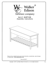
2) GENERAL OUTLINE
Compact electromechanical barrier suitable for limiting private areas, parkings,
access areas for vehicles only. Available for passageways from 4 to 8 metres.
Adjustable electronic limit switches, they guarantee correct boom stopping
position. In case of intensive use, a thermal sensor activates the cooling fan.
The emergency release device for manual manoeuvre is controlled by a key lock.
The actuator is always supplied for left-hand side tting. However, when nec-
essary, the opening direction can be reversed by means of simple operations.
The BM mod. foundation base (on request) makes barrier installation easier.
Appropriate ttings make it easy to install accessories.
The MERAK BM6-MERAK BM8 control panel is supplied by the manufacturer
with standard setting. Any change must be set by means of the incorporated
display or by means of the universal programmer.
Its main features are:
- Control of 1 low-voltage motor
- Obstacle detection
- Separate inputs for safety devices
- Congurable command inputs
- Built-in radio receiver rolling code with transmitter cloning.
The board has a terminal strip of the removable kind to make maintenance
or replacement easier. It comes with a series of prewired jumpers to make the
installer’s job on site easier. The jumpers concern terminals: 70-71, 70-72, 70-74.
If the above-mentioned terminals are being used, remove the relevant jumpers.
TESTING
The MERAK BM6-MERAK BM8 panel controls (checks) the start relays and
safety devices (photocells) before performing each opening and closing cycle.
If there is a malfunction, make sure that the connected devices are working
properly and check the wiring.
3) TECHNICAL SPECIFICATIONS
Power supply: 230V±10% 50/60Hz(*)
Power absorbed: 300W
Absorption (with accessories): 1 A
Internal lubrication:
permanent grease
Max torque: 600 Nm
Opening time: 6s (5-6m), 8s (8m),
Boom length:
4m (ML MCL40)
5-6m (MICHELANGELO BT A 60)
da 6m a 8m (MICHELANGELO BT
A 80)
Impact reaction: encoder
Manual mechanical release: key
Type of boom: rectangular/round
Limit devices:
electrical incorporated and electroni-
cally adjustable
Type of use continuous operation
Working temperature: from -20°C to +55°C
Degree of protection: IP 54
Operator weight (without boom):
58 Kg (MICHELANGELO BT A 60)
68 Kg (MICHELANGELO BT A 80)
Dimensions: see g. A
Mains/low voltage insulation: > 2MOhm 500V
Dielectric strength:
mains/low voltage 3750V~ for 1
minute
Motor output current:
20A max (ML MCL40)
25A max (MICHELANGELO BT A 60)
30A max (MICHELANGELO BT A 80)
Supply to accessories: 24V~ (180 mA max absorption)
Barrie-open warning light: 24V~ 3W max
Blinker: 24V~ 25W max
Fuses: see gure I-H
N° of combinations:
4 billion
Max. n° of remotes that
can be memorized:
63
(*)= special power supply voltages on request.
Usable transmitter versions:
All ROLLING CODE transmitters compatible with
4.1) FOUNDATION PLATE (Fig. B1).
4.2) FASTENING ANCHOR BOLTS (Fig. B2).
5) FITTING OF THE ACTUATOR
WARNING! The barrier must be exclusively used for vehicles to
drive through. Pedestrians must not walk within the operator
manoeuvring area. An appropriate pedestrian passageway must be
provided for.
The passageway must be suitably indicated by means of the warning
signs illustrated in Fig.A.
WARNING: before opening the door, the spring must be unloaded (vertical
boom). The door of the box must be facing towards the inside of the property.
When you stand in the middle of the passageway, facing outwards, if the box
is on your left, the barrier is left-hand tted, if the box is on your right, the
barrier is right-hand tted.
The actuator is always supplied for left-hand side tting.
5.1) COVER AND DOOR OPENING AND CLOSING (Fig. C).
5.2) POSITIONING OF ENCLOSURE FIG.D
5.3) BOOM FIXING (Fig. E).
6) MICHELANGELO BT A 60 accessories: boom length limits and balancing
(Fig. G1).
For further information about the installation and use of accessories, refer to
the respective instruction manuals.
6.1) MICHELANGELO BT A 80 accessories: (Fig. F1/F2)
6.2) BAR BALANCING (Fig. F3).
6.3) ATTACHMENT AND TENSIONING OF SPRING g. AC-AD
7) Right-hand tting (Fig. AA, AB)
- Carry out bar balancing as described in Fig. G3.
- Set the Direction Reversal logic to ON in the control panel.
Warning: the Direction Reversal logic must be congured to OFF
for left-hand tted barriers, and to ON for right-hand tted barri-
ers. Otherwise, the limit devices will not operate or an encoder direction
error will be displayed.
8) FITTING THE FLASHING LIGHT (FIG AE)
Complete assembly and wiring as directed in instructions provided for
the ashing light
9) FITTING THE PHOTOCELL (FIG AF).
Complete assembly as directed in instructions provided for the photocell
----------------------------------------------------------
10) ELECTRICAL INSTALLATION SET-UP
WARNING: before opening the door, the spring must be unloaded (ver-
tical boom). Set up the electrical installation (g. A) with reference to the
current regulations for electrical installations. Keep the mains power supply
con-nections denitely separate from the service connections (photocells,
electric edges, control devices etc.).
Warning! For connection to the mains, use a multipolar cable having
minimum 3x1.5mm
2
cross section and complying with the previously
mentioned regulations (for example, if the cable is not protected, it must
be at least equal to H07 RN-F, whereas if it is protected it must be at least
equal to H07 VV-F with a 3x1.5 sq mm
2
cross section).
Fig. A shows the number of connections and section for a 100m length of
power supply cables; for greater lengths, calculate the section for the true
automation load. When the auxiliary connections exceed 50 metre lengths
or go through critical disturbance areas, it is recommended to decouple the
control and safety devices by means of suitable relays.
The main automation components are (g. A):
I) Type-approved adequately rated omnipolar circuit-breaker with at least
3,5 mm contact opening, provided with protection against overloads
and short circuits, suitable for cutting out automation from the mains.
Place, if not al ready installed, a type-approved dierential switch with
a 0.03A threshold just before the automation system.
QR) Control panel and incorporated receiver.
S) Key selector.
AL) Blinker
M) Actuators.
A) Bar.
F) Rest fork.
CS) Electric edge.
Ft,Fr) Pair of photocells.
CF) Photocell post.
T) 1-2-4 channel transmitter.
RMM) Inductive metal mass detector.
LOOP) Mass detector loops.
11) CONNECTION (FIg. G-I)
WARNING: The electrical connections must be carried out workmanlike by
ENGLISH
MICHELANGELO BT A- 33
D812218 00100_01

INSTALLATION MANUAL
qualied experienced personnel, in conformity with all the current standards
and with the use of appropriate materials.
Lay out the electrical installation with reference to the current electrical
standards.
Keep the mains supply connections clearly separated from the service con-
nections.
In the initial section of the electrical installation, t a circuit breaker with a
contact opening distance equal to or greater than 3,5 mm, provided with mag-
netothermal protection and a dierential switch having adequate capacity for
the appliance consumption. For the wiring, only use cables conforming to the
harmonised or national standards, having a cross section corresponding to the
initial protection, the appliance consumption and the installation conditions,
for example a 3x1.5 sq mm (H 05 VV-F) cable.
Proceed as explained below:
1. Remove the transformer cover.
2. Unscrew the screw which locks the cap (Fig. G Rif. 1) and take the cap out.
3. Fix the cables to the terminal bar (Fig. G Rif. 2)
L PHASE
N NEUTRAL
EARTH
4. To close the cap, reverse the actions in step 2.
5. Ret the transformer cover and secure in place by means of the slots located
on top of the transformer (Fig. G Rif. 3-4).
INSTALLATION MANUAL
Terminal Denition Description
Power supply
JP13 TRANSF SEC
Board power supply:
24V~ Transformer secondary winding
JPC29 RECTIFIER BRIDGE Rectier bridge connection
Motor
10 MOT +
Connection motor 1
11 MOT -
Aux
20
AUX 0 - 24V POWERED CONTACT
(N.O.) (MAX. 1A)
AUX 0 congurable output - Default setting FLASHING LIGHT.
2ND RADIO CHANNEL/ SCA GATE OPEN LIGHT/ COURTESY LIGHT command/ ZONE LIGHT command/ STAIR LIGHT/
GATE OPEN ALARM/ FLASHING LIGHT/ SOLENOID LATCH/ MAGNETIC LOCK/ MAINTENANCE/ FLASHING LIGHT AND
MAINTENANCE. Refer to “AUX output conguration” table.
21
26
AUX 3 - FREE CONTACT (N.O.)
(Max. 24V 1A)
AUX 3 congurable output - Default setting 2ND RADIO CHANNEL Output.
2ND RADIO CHANNEL/ SCA GATE OPEN LIGHT/ COURTESY LIGHT command/ ZONE LIGHT command/ STAIR LIGHT/
GATE OPEN ALARM/ FLASHING LIGHT/ SOLENOID LATCH/ MAGNETIC LOCK/ MAINTENANCE/ FLASHING LIGHT AND
MAINTENANCE. Refer to “AUX output conguration” table.
27
Limit
switches
41 + REF RIF Common references
42 RIFC Reference closing RIFC (N.C.)
43 RIFO Reference opening RIFO (N.C.)
Accessories
power
supply
50 24V-
Accessories power supply output.
51 24V+
52 24 Vsafe+
Tested safety device power supply output (photocell transmitter and safety edge transmitter).
Output active only during operating cycle.
Commands
60 Common IC 1 and IC 2 inputs common
61 IC 1
Congurable command input 1 (N.O.) - Default START E.
START E / START I / OPEN / CLOSE / PED / TIMER / TIMER PED
Refer to the “Command input conguration” table.
62 IC 2
Congurable command input 2 (N.O.) - Default TIMER.
START E / START I / OPEN / CLOSE / PED / TIMER / TIMER PED
Refer to the “Command input conguration” table.
Safety devices
70 Common STOP, SAFE 1 and SAFE 2 inputs common
71 STOP
The command stops movement. (N.C.)
If not used, leave jumper inserted.
72 SAFE 1
Congurable safety input 1 (N.C.) - Default PHOT.
PHOT / PHOT TEST / PHOT OP / PHOT OP TEST / PHOT CL / PHOT CL TEST / BAR / BAR TEST / BAR 8K2
Refer to the “Safety input conguration” table.
73 FAULT 1 Test input for safety devices connected to SAFE 1.
74 SAFE 2
Congurable safety input 2 (N.C.) - Default BAR.
PHOT / PHOT TEST / PHOT OP / PHOT OP TEST / PHOT CL / PHOT CL TEST / BAR / BAR TEST / BAR 8K2
Refer to the “Safety input conguration” table.
75 FAULT 2 Test input for safety devices connected to SAFE 2.
Antenna
Y ANTENNA
Antenna input.
Use an antenna tuned to 433MHz. Use RG58 coax cable to connect the Antenna and Receiver. Metal bodies close
to the antenna can interfere with radio reception. If the transmitter’s range is limited, move the antenna to a more
suitable position.
# SHIELD
AUX output conguration
Aux logic= 0 - 2ND RADIO CHANNEL output.
Contact stays closed for 1s when 2nd radio channel is activated.
Aux logic= 1 - SCA GATE OPEN LIGHToutput.
Contact stays closed during opening and with leaf open, intermittent during closing, open with leaf closed.
Aux logic= 2 - COURTESY LIGHT command output.
Contact stays on for 90 seconds after the last operation.
Aux logic= 3 - ZONE LIGHT command output.
Contact stays closed for the full duration of operation.
Aux logic= 4 - STAIR LIGHT output.
Contact stays closed for 1 second at start of operation.
Aux logic= 5 - GATE OPEN ALARM output.
The contact remains closed if the door stays open for longer than the “alarm time” parameter.
Aux logic= 6 - FLASHING LIGHT output.
Contact stays closed while leaves are operating.
34 - MICHELANGELO BT A
D812218 00100_01
/