
COPYRIGHT © SEPTEMBER, 2015 BY GRIZZLY INDUSTRIAL, INC.
WARNING: NO PORTION OF THIS MANUAL MAY BE REPRODUCED IN ANY SHAPE
OR FORM WITHOUT THE WRITTEN APPROVAL OF GRIZZLY INDUSTRIAL, INC.
#JH17636 PRINTED IN CHINA
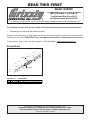
Revised Parts
The following changes were recently made to this machine since the manual insert was printed:
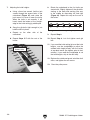
• Changed spiral cutterhead and indexable inserts.
Aside from this information, all other content in the owner's manual applies and MUST be read and under-
stood for your own safety. IMPORTANT: Keep this update with the owner's manual for future reference.
For questions or help, contact our Tech Support at (570) 546-9663 or [email protected].
READ THIS FIRST
For questions or help with this product contact Tech Support at (570) 546-9663 or techsupport@grizzly.com
Model G0609X
***IMPORTANT UPDATE***
For Machines Mfd. Since 04/15
and Manual Insert Revised 07/08
23V2
18
19
20
21
27
30
28
29
32
33
26
24V2
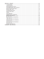
REF PART # DESCRIPTION
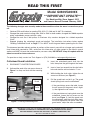
23V2 P0609X023V2 SPIRAL CUTTERHEAD 12" V2.04.15
24V2 P0609X024V2 INDEXABLE INSERT 14 X 14 X 2MM V2.04.15

The following changes were recently made to these machines since the owner's manual was print-
ed:
Page 17You MUST install the guard before operating the first time!
IMPORTANT: Keep this update with the
owner's manual for future reference.
For questions or help, contact our Tech Support at (570) 546-9663 or [email protected].
WARNING: NO PORTION OF THIS MANUAL MAY BE REPRODUCED IN ANY SHAPE
OR FORM WITHOUT THE WRITTEN APPROVAL OF GRIZZLY INDUSTRIAL, INC.
Model G0609/G0609X
***IMPORTANT UPDATE***
For Machines Mfg. Since August, 2012
and Owner's Manual Revised February, 2008
READ THIS FIRST
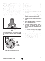
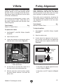
3.
4.
5.
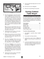
Figure 1
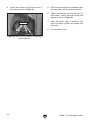
6.
Figure 1
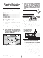
Cutterhead Guard Installation
1.
2.
Figure 1
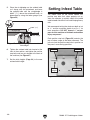
Figure 1.

Changed Specifications
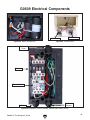
Electrical
Motor
Operation Info
)%&K'
(()K'
(&*6"&
(&*6
(&*6"-
(&*6".
(&*6"&%
(&*6"'
(&*6"(
(&*6",
(&*6"*
(&*6"+
(&*6")
&+K'
&,K'
(&+K'
(*+K'
(()"'
(()"(
(()")
(()"(
(()"&
)%&K'
(&*"&K'
(&*K'
(&*"(K'
(&*"'K'
(&*",K'
(&*"*K'
(&*"+K'
(&*")K'
(&*K'"&%
(&*K'".
(&*K'"-
&+K'
&,K'
(&+K'
(*+K'
(()"'
(()"(
(()")
(()"(
(()K'
(()"&
)%&K'
(()K'
(&*6"&
(&*6
(&*6"-
(&*6".
(&*6"&%
(&*6"'
(&*6"(
(&*6",
(&*6"*
(&*6"+
(&*6")
&+K'
&,K'
(&+K'
(*+K'
(()"'
(()"(
(()")
(()"(
(()"&
)%&K'
(&*"&K'
(&*K'
(&*"(K'
(&*"'K'
(&*",K'
(&*"*K'
(&*"+K'
(&*")K'
(&*K'"&%
(&*K'".
(&*K'"-
&+K'
&,K'
(&+K'
(*+K'
(()"'
(()"(
(()")
(()"(
(()K'
(()"&
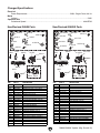
New/Revised G0609 Parts
REF PART # DESCRIPTION
16V2 P0609016V2 ALUM CUTTERHEAD PULLEY V2.03.09
17V2 P0609017V2 RIBBED V-BELT 8PK-1371 V2.03.09
315A P0453430A MOTOR 3HP 230V 1-PH V2.03.08
315A-1 PK33M KEY 5 X 5 X 45
315A-2 P0453430A-1 MOTOR FAN COVER V2.03.08
315A-3 P0453430A-2 MOTOR FAN V2.03.08
315A-4 P0453430A-9 CENTRIFUGAL SWITCH 16MM 3450
315A-5 P0453430A-5 S CAPACITOR 200M 250V V2.03.08
315A-6 P0453430A-4 R CAPACITOR 20M 400V V2.03.08
315A-7 P0453430A-6 JUNCTION BOX V2.03.08
315A-8 P6205ZZ BALL BEARING 6205ZZ
315A-9 P6203ZZ BALL BEARING 6203ZZ
315A-10 P0453430A-10 CONTACT PLATE 16MM
316V2 P0609316V2 ALUMINUM MOTOR PULLEY V2.03.09
334V2 P0609334V2 MAGNETIC SWITCH V2.01.11
334-1 PS06M PHLP HD SCR M5-.8 X 20
334-2 P0609334-2 CONTACTOR NHD C-12D 230V
334-3 P0609334-3 MAG SWITCH COVER ASSEMBLY
334-4 P0609334-4 OL RELAY NHD NTH-17 14-17A
334-5 P0609334-3 MAG SWITCH COVER ASSEMBLY
356V2 P0453119V2 PWR CORD 12G 3W 72" 6-20P V2.08.12
401V2 P0609401V2 MACHINE ID LABEL CSA V2.08.12
REF PART # DESCRIPTION
16V2 P0609016V2 CUTTERHEAD PULLEY, ALUM V2.03.09
17V2 P0609017V2 RIBBED V-BELT 8PK-1371 V2.03.09
315V2 P0453Z518V2 MOTOR 3HP 230V 1-PH V2.05.08
315-1V2 PK33M KEY 5 X 5 X 45
315-2V2 P0453Z518-1 MOTOR FAN COVER
315-3V2 P0453Z518-2 MOTOR FAN
315-4V2 P0609X315-4V2 CENTRIFUGAL SWITCH 16MM 3450
315-5V2 P0453Z518-3V2 S CAPACITOR 250M 250V 1-3/4 X 3-1/2
315-6V2 P0453Z518-4V2 R CAPACITOR 40M 450V 1-3/8 X 2-3/8
315-7V2 P0453Z518-5V2 JUNCTION BOX V2.05.08
315V2-8 P6205ZZ BALL BEARING 6205ZZ
315V2-9 P6203ZZ BALL BEARING 6203ZZ
315V2-10 P0453Z518-9 CONTACT PLATE 16MM
316V2 P0609316V2 ALUM MOTOR PULLEY V2.03.09
334V2 P0609334V2 MAGNETIC SWITCH V2.01.11
334-1 PS06M PHLP HD SCR M5-.8 x 20
334-2 P0609334-2 CONTACTOR NHD C-12D 230V
334-3 P0609334-3 MAG SWITCH COVER ASSEMBLY
334-4 P0609334-4 OL RELAY NHD NTH-17 14-17A
334-5 P0609334-3 MAG SWITCH COVER ASSEMBLY
356V2 P0453119V2 PWR CORD 12G 3W 72" 6-20P V2.08.12
401V2 P0609X401V2 MACHINE ID LABEL CSA V2.08.12
New/Revised G0609X Parts

ELECTRICAL EQUIPMENT INJURY RISKS.
DISCONNECT POWER FIRST.
EYE PROTECTION.
OWNER’S MANUAL.
TRAINED OPERATORS ONLY.
DANGEROUS ENVIRONMENTS.
MENTAL ALERTNESS REQUIRED.
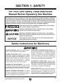
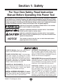
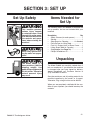
For Your Own Safety, Read Instruction
Manual Before Operating this Machine
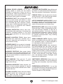
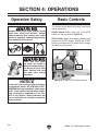
The purpose of safety symbols is to attract your attention to possible hazardous conditions.
This manual uses a series of symbols and signal words intended to convey the level of impor-
tance of the safety messages. The progression of symbols is described below. Remember that
safety messages by themselves do not eliminate danger and are not a substitute for proper
accident prevention measures. Always use common sense and good judgement.
Indicates a potentially hazardous situation which, if not avoided,
MAY result in minor or moderate injury. It may also be used to alert
against unsafe practices.
Indicates a potentially hazardous situation which, if not avoided,
COULD result in death or serious injury.
Indicates an imminently hazardous situation which, if not avoided,
WILL result in death or serious injury.
This symbol is used to alert the user to useful information about
proper operation of the machine.
NOTICE
Safety Instructions for Machinery
SECTION 1: SAFETY

WEARING PROPER APPAREL.
HAZARDOUS DUST.
HEARING PROTECTION.
REMOVE ADJUSTING TOOLS.
INTENDED USAGE.
AWKWARD POSITIONS.
CHILDREN & BYSTANDERS.
GUARDS & COVERS.
FORCING MACHINERY.
NEVER STAND ON MACHINE.
STABLE MACHINE.
USE RECOMMENDED ACCESSORIES.
UNATTENDED OPERATION.
OFF
MAINTAIN WITH CARE.
CHECK DAMAGED PARTS.
MAINTAIN POWER CORDS.
EXPERIENCING DIFFICULTIES.

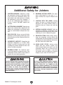
Additional Safety for Jointers
JOINTER INJURY RISKS.
Main injury
risks from jointers:
KICKBACK.
GUARD REMOVAL.
OFF
DULL/DAMAGED KNIVES/INSERTS.
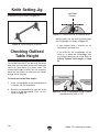
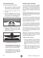
OUTFEED TABLE ALIGNMENT.
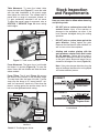
INSPECTING STOCK.
GRAIN DIRECTION.
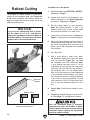
CUTTING LIMITATIONS.
MAXIMUM CUTTING DEPTH
PUSH BLOCKS.
WORKPIECE SUPPORT.
FEED WORKPIECE PROPERLY.
SECURE KNIVES/INSERTS.

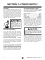
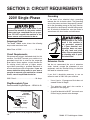
SECTION 2: POWER SUPPLY
Availability
7Z[dgZ^chiVaa^c\i]ZbVX]^cZ!Xdch^YZgi]ZVkV^a"
VW^a^inVcYegdm^b^ind[i]ZgZfj^gZYedlZghjeean
X^gXj^i# >[ Vc Zm^hi^c\ X^gXj^i YdZh cdi bZZi i]Z
gZfj^gZbZcih[dgi]^hbVX]^cZ!VcZlX^gXj^ibjhi
WZ^chiVaaZY#Idb^c^b^oZi]Zg^h`d[ZaZXigdXji^dc!
[^gZ!dg Zfj^ebZciYVbV\Z!^chiVaaVi^dcldg` VcY
ZaZXig^XVal^g^c\bjhiWZYdcZWnVcZaZXig^XVcdg
fjVa^[^ZYhZgk^XZeZghdccZa^cVXXdgYVcXZl^i]Vaa
Veea^XVWaZXdYZhVcYhiVcYVgYh#
Electrocution, fire, or
equipment damage may
occur if machine is not
correctly grounded and
connected to the power
supply.
Full-Load Current Rating
I]Z [jaa"adVY XjggZci gVi^c\ ^h i]Z VbeZgV\Z V
bVX]^cZYgVlhVi&%%d[i]ZgViZYdjiejiedlZg#
Dc bVX]^cZh l^i] bjai^eaZ bdidgh! i]^h ^h i]Z
VbeZgV\ZYgVlcWni]ZaVg\Zhibdidgdghjbd[Vaa
bdidghVcY ZaZXig^XVa YZk^XZh i]Vib^\]ideZgViZ
VidcZi^bZYjg^c\cdgbVadeZgVi^dch#
Full-Load Current Rating at 230V ..... 15 Amps
I]Z[jaa"adVYXjggZci^hcdii]ZbVm^bjbVbdjci
d[Vbehi]Vii]ZbVX]^cZl^aaYgVl#>[i]ZbVX]^cZ
^hdkZgadVYZY!^il^aaYgVlVYY^i^dcVaVbehWZndcY
i]Z[jaa"adVYgVi^c\#
>[i]ZbVX]^cZ^hdkZgadVYZY[dgVhj[[^X^ZciaZc\i]
d[i^bZ!YVbV\Z!dkZg]ZVi^c\!dg[^gZbVngZhjai·
ZheZX^Vaan ^[ XdccZXiZY id Vc jcYZgh^oZY X^gXj^i#
IdgZYjXZ i]Z g^h` d[ i]ZhZ]VoVgYh! Vkd^Y dkZg"
adVY^c\ i]Z bVX]^cZ Yjg^c\ deZgVi^dc VcY bV`Z
hjgZ^i^hXdccZXiZYidVedlZghjeeanX^gXj^ii]Vi
bZZihi]ZgZfj^gZbZcih^ci]Z[daadl^c\hZXi^dc#
Circuit Requirements for 230V
I]^h bVX]^cZ ^h egZl^gZY id deZgViZ dc V '(%K
edlZghjeeanX^gXj^ii]Vi]VhVkZg^[^ZY\gdjcYVcY
bZZihi]Z[daadl^c\gZfj^gZbZcih/
Nominal Voltage ........................................230V
Cycle ..........................................................60 Hz
Phase .................................................... 1-Phase
Circuit Rating ...................................... 20 Amps
Plug/Receptacle ............................. NEMA 6-20
For your own safety and protection of
property, consult an electrician if you are
unsure about wiring practices or electrical
codes in your area.
Note: The circuit requirements listed in this man-
ual apply to a dedicated circuit—where only one
machine will be running at a time. If this machine
will be connected to a shared circuit where mul-
tiple machines will be running at the same time,
consult a qualified electrician to ensure that the
circuit is properly sized for safe operation.
6 edlZg hjeean X^gXj^i ^cXajYZh Vaa ZaZXig^XVa
Zfj^ebZciWZilZZci]ZWgZV`ZgWdmdg[jhZeVcZa
^ci]ZWj^aY^c\VcYi]ZbVX]^cZ#I]ZedlZghje"
eanX^gXj^ijhZY[dgi]^hbVX]^cZbjhiWZh^oZYid
hV[Zan]VcYaZi]Z[jaa"adVYXjggZciYgVlc[gdbi]Z
bVX]^cZ [dg Vc ZmiZcYZY eZg^dY d[ i^bZ# >[ i]^h
bVX]^cZ ^h XdccZXiZY id V X^gXj^i egdiZXiZY Wn
[jhZh!jhZVi^bZYZaVn[jhZbVg`ZY9#

Extension Cords
LZ Yd cdi gZXdbbZcY jh^c\ Vc ZmiZch^dc XdgY
l^i] i]^h bVX]^cZ#>[ ndj bjhi jhZ Vc ZmiZch^dc
XdgY!dcanjhZ^i^[VWhdajiZancZXZhhVgnVcYdcan
dcViZbedgVgnWVh^h#
:miZch^dc XdgYh XVjhZ kdaiV\Z Ygde! l]^X] bVn
YVbV\ZZaZXig^XVaXdbedcZcihVcYh]dgiZcbdidg
a^[Z#KdaiV\ZYgde^cXgZVhZhVhi]ZZmiZch^dcXdgY
h^oZ\Zihadc\ZgVcYi]Z\Vj\Zh^oZ\ZihhbVaaZg
]^\]Zg\Vj\ZcjbWZgh^cY^XViZhbVaaZgh^oZh#
6cnZmiZch^dcXdgYjhZYl^i]i]^hbVX]^cZbjhi
XdciV^c V \gdjcY l^gZ! bViX] i]Z gZfj^gZY eaj\
VcY gZXZeiVXaZ! VcY bZZi i]Z [daadl^c\ gZfj^gZ"
bZcih/
Minimum Gauge Size ...........................12 AWG
Maximum Length (Shorter is Better).......50 ft.
Grounding Instructions
I]^h bVX]^cZ BJHI WZ \gdjcYZY# >c i]Z ZkZci
d[XZgiV^cbVa[jcXi^dchdgWgZV`Ydlch!\gdjcY^c\
gZYjXZhi]Z g^h` d[ ZaZXig^X h]dX`Wnegdk^Y^c\V
eVi]d[aZVhigZh^hiVcXZ[dgZaZXig^XXjggZci#
>begdeZgXdccZXi^dcd[i]ZZfj^ebZci"\gdjcY^c\
l^gZ XVc gZhjai ^c V g^h` d[ ZaZXig^X h]dX`# I]Z
l^gZl^i] \gZZc^chjaVi^dcl^i]dgl^i]djinZaadl
hig^eZh^hi]ZZfj^ebZci"\gdjcY^c\l^gZ#>[gZeV^g
dggZeaVXZbZcid[i]ZedlZgXdgYdgeaj\^hcZX"
ZhhVgn!YdcdiXdccZXii]ZZfj^ebZci"\gdjcY^c\
l^gZidVa^kZXjggZciXVggn^c\iZgb^cVa#
8]ZX`l^i]VfjVa^[^ZYZaZXig^X^VcdghZgk^XZeZg"
hdccZa^[ndjYdcdijcYZghiVcYi]ZhZ\gdjcY^c\
gZfj^gZbZcih!dg^[ndjVgZ^cYdjWiVWdjil]Zi]Zg
i]Z idda ^h egdeZgan \gdjcYZY# >[ ndj ZkZg cdi^XZ
i]ViVXdgYdgeaj\^h YVbV\ZY dg ldgc!Y^hXdc"
cZXi^i[gdbedlZg!VcY^bbZY^ViZangZeaVXZ^il^i]
VcZldcZ#
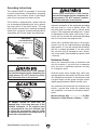
Serious injury could occur if you connect
the machine to power before completing the
setup process. DO NOT connect to power
until instructed later in this manual.
No adapter should be used with the
required plug. If the plug does not fit the
available receptacle, or the machine must
be reconnected for use on a different type
of circuit, the reconnection must be made
by a qualified electrician and comply with all
local codes and ordinances.
Serious injury could occur if you connect
the machine to power before completing the
setup process. DO NOT connect to power
until instructed later in this manual.
Figure 2.
<gdjcY^c\Egdc\
8jggZci8Vggn^c\Egdc\h
6-20 PLUG
GROUNDED
6-20 RECEPTACLE
I]^hbVX]^cZ^hZfj^eeZYl^i]VedlZgXdgYi]Vi
]VhVcZfj^ebZci"\gdjcY^c\l^gZVcYV\gdjcY"
^c\ eaj\ h^b^aVg id i]Z [^\jgZ WZadl# I]Z eaj\
bjhidcanWZ^chZgiZY^cidVbViX]^c\gZXZeiVXaZ
djiaZii]Vi^hegdeZgan^chiVaaZYVcY\gdjcYZY^c
VXXdgYVcXZl^i]VaaadXVaXdYZhVcYdgY^cVcXZh#

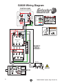
G0609 Wiring Diagram
&A& (A' *A(
'I& )I' +I(
'I& )I' +I(
&(cd
&)cd
6'
.-
6'
6&
., .+ .*
=di
<gdjcY
=di
WARNING!
SHOCK HAZARD!
Disconnect power
before working on
wiring.
7A68@
L=>I:
<G::C
G:9
7AJ:
COLOR KEY
7`
Li
<c
GY
7a
CONTROL PANEL
k^ZlZY[gdbWZ]^cY
<c
HI6GI
HIDE
GY
GY
GY
GYGY
GY
GY
GY
GY
7a
7a
7`
7`
<c
7`
7`
Li
Li
MAGNETIC
SWITCH
ASSEMBLY
GY
GY
GY
7a
Li
7`
<c
Li
Li
<c
<c
<c
Li
Li
<c
7` Li
GY
GY
GY
GY
Hot
Hot
Ground
6-20 Plug
230
VAC
<
230 VAC
C=9CI="&,
C=98"&'9
'(%K
7`
7`
GY
MOTOR
<gdjcY
HiVgi
8VeVX^idg
'%%B;9
'*%K68
Gjc
8VeVX^idg
'%B;9
)%%K68
<gdjcY
<gdjcY

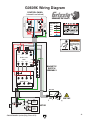
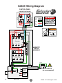
G0609X Wiring Diagram
MOTOR
&A& (A' *A(
'I& )I' +I(
'I& )I' +I(
&(cd
&)cd
6'
.-
6'
6&
., .+ .*
=di
<gdjcY
=di
WARNING!
SHOCK HAZARD!
Disconnect power
before working on
wiring.
7A68@
L=>I:
<G::C
G:9
7AJ:
COLOR KEY
7`
Li
<c
GY
7a
CONTROL PANEL
k^ZlZY[gdbWZ]^cY
<c
HI6GI
HIDE
GY
GY
GY
GYGY
GY
GY
GY
GY
7a
7a
7`
7`
<c
7`
7`
Li
Li
MAGNETIC
SWITCH
ASSEMBLY
GY
GY
GY
7a
Li
7`
<c
Li
Li
<c
<c
<c
Li
Li
<c
7` Li
GY
GY
GY
GY
Hot
Hot
Ground
6-20 Plug
230
VAC
<
230 VAC
7`
7`
<c
Li
Li
Li
C=9CI="&,
C=98"&'9
'(%K
7`
7`
GY
<gdjcY
HiVgi
8VeVX^idg
'*%B;9
'*%K68
Gjc
8VeVX^idg
)%B;9
)*%K68
GY
<gdjcY
<gdjcY

Buy Direct and Save with Grizzly
®
– Trusted, Proven and a Great Value!
~Since 1983~
ORDER
24 HOURS A DAY!
1-800-523-4777
Visit Our Website Today For
Current Specials!

COPYRIGHT © MARCH, 2008 BY GRIZZLY INDUSTRIAL, INC.
WARNING: NO PORTION OF THIS MANUAL MAY BE REPRODUCED IN ANY SHAPE
OR FORM WITHOUT THE WRITTEN APPROVAL OF GRIZZLY INDUSTRIAL, INC.
#BL10618 PRINTED IN CHINA
This update covers improvements made to this machine after the owner's manual was printed. Keep this
update with your owner's manual for future reference. If you have questions, contact Tech Support at (570)
546-9663 or by email at [email protected].
Why the Update?
We recently re-designed the G0609 motor and
changed the capacitor wiring. Figure 1 shows the
ne
w motor wiring for both models.
Figure 1. Model G0609 new motor and capacitor
wiring.
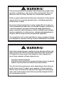
MODEL G0609
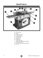
12" PARALLELOGRAM JOINTER
MANUAL UPDATE
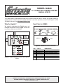
Figure 2. G0609 new motor breakdown.
New Parts for G0609
REF PART # DESCRIPTION
315A P0609315A MOTOR 3HP 220V V2.03.08
315A-1 PK33M KEY 5 X 5 X 45
315A-2 P0609315A-2 MOTOR FAN COVER V2.03.08
315A-3 P0609315A-3 MOTOR FAN V2.03.08
315A-4 P0609315A-4 CENTRIFUGAL SWITCH V2.03.08
315A-5 P0609315A-5 S CAP 200M 250V
315A-6 P0609315A-6 R CAP 20M 400V
315A-7 P0609315A-7 JUNCTION BOX V2.03.08


COPYRIGHT © SEPTEMBER, 2007 BY GRIZZLY INDUSTRIAL, INC. REVISED JULY, 2008. (TR)
WARNING: NO PORTION OF THIS MANUAL MAY BE REPRODUCED IN ANY SHAPE
OR FORM WITHOUT THE WRITTEN APPROVAL OF GRIZZLY INDUSTRIAL, INC.
#TR10028 PRINTED IN CHINA
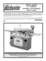
The Model G0609X is the same as the Model G0609, except it has a spiral cutterhead. Besides the
data sheet and parts in this insert, the content in the Model G0609 owner's manual is the same for both
machines. Before operating your new machine, you MUST read and understand this insert and the entire
Model G0609 manual to reduce the risk of injury from improper use or setup.
If you have any further questions about this manual insert or the differences between the Model G0609X
and the Model G0609, contact our Technical Support at (570) 546-9663 or email techsupport@grizzly.
com.
MODEL G0609X
12" JOINTER
w/SPIRAL CUTTERHEAD
MANUAL INSERT

Model G0609X -1-
The information contained herein is deemed accurate as of 8/6/2017 and represents our most recent product specifications.
Due to our ongoing improvement efforts, this information may not accurately describe items previously purchased.
PAGE 1 OF 3
Model G0609X
MACHINE DATA
SHEET
Customer Service #: (570) 546-9663 · To Order Call: (800) 523-4777 · Fax #: (800) 438-5901
MODEL G0609X 12" JOINTER W/ SPIRAL CUTTERHEAD
Product Dimensions:
Weight.............................................................................................................................................................. 884 lbs.
Width (side-to-side) x Depth (front-to-back) x Height..................................................................... 84 x 33 x 43-1/2 in.
Footprint (Length x Width)............................................................................................................................ 46 x 24 in.
Shipping Dimensions:
Type.......................................................................................................................................................... Wood Crate
Content........................................................................................................................................................... Machine
Weight............................................................................................................................................................ 1056 lbs.
Length x Width x Height....................................................................................................................... 30 x 89 x 41 in.
Must Ship Upright................................................................................................................................................... Yes
Electrical:
Power Requirement........................................................................................................... 230V, Single-Phase, 60 Hz
Prewired Voltage.................................................................................................................................................. 230V
Full-Load Current Rating........................................................................................................................................ 15A
Minimum Circuit Size.............................................................................................................................................. 20A
Connection Type....................................................................................................................................... Cord & Plug
Power Cord Included.............................................................................................................................................. Yes
Power Cord Length................................................................................................................................................. 7 ft.
Power Cord Gauge......................................................................................................................................... 12 AWG
Plug Included........................................................................................................................................................... No
Recommended Plug Type..................................................................................................................................... 6-20
Switch Type......................................................................................... Button Controls w/Magnetic Switch Protection
Motors:
Main
Horsepower................................................................................................................................................ 3 HP
Phase............................................................................................................................................ Single-Phase
Amps............................................................................................................................................................ 15A
Speed................................................................................................................................................ 3450 RPM
Type................................................................................................................. TEFC Capacitor-Start Induction
Power Transfer ............................................................................................................................... V-Belt Drive
Bearings..................................................................................................... Shielded & Permanently Lubricated
Main Specifications:
Main Specifications
Jointer Size................................................................................................................................................ 12 in.
Bevel Jointing............................................................................................................................. 0 – 45 deg. L/R
Maximum Width of Cut.............................................................................................................................. 12 in.
Maximum Depth of Cut............................................................................................................................. 1/8 in.
Minimum Workpiece Length...................................................................................................................... 14 in.
Minimum Workpiece Thickness................................................................................................................ 1/2 in.
Maximum Rabbeting Depth...................................................................................................................... 3/4 in.
Number of Cuts Per Minute..................................................................................................................... 19,800

Model G0609X-2-
The information contained herein is deemed accurate as of 8/6/2017 and represents our most recent product specifications.
Due to our ongoing improvement efforts, this information may not accurately describe items previously purchased.
PAGE 2 OF 3
Model G0609X
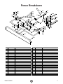
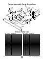
Fence Information
Fence Length....................................................................................................................................... 46-3/4 in.
Fence Width.......................................................................................................................................... 1-1/2 in.
Fence Height......................................................................................................................................... 5-3/8 in.
Fence Stops............................................................................................................................. 45, 90, 135 deg.
Cutterhead Information
Cutterhead Type........................................................................................................................................ Spiral
Cutterhead Diameter............................................................................................................................. 3-7/8 in.
Number of Cutter Spirals.................................................................................................................................. 4
Number of Indexable Cutters.......................................................................................................................... 60
Cutterhead Speed............................................................................................................................. 4300 RPM
Cutter Insert Information
Cutter Insert Type.................................................................................................................. Indexable Carbide
Cutter Insert Length................................................................................................................................. 14 mm
Cutter Insert Width................................................................................................................................... 14 mm
Cutter Insert Thickness.............................................................................................................................. 2 mm
Table Information
Table Length........................................................................................................................................ 83-1/2 in.
Table Width......................................................................................................................................... 12-3/4 in.
Table Thickness........................................................................................................................ 1-7/8 – 3-1/4 in.
Floor to Table Height....................................................................................................................... 31-11/16 in.
Table Adjustment Type..................................................................................................................... Handwheel
Table Movement Type.................................................................................................................. Parallelogram
Construction
Base..................................................................................................................................................... Cast Iron
Body Assembly.................................................................................................................................... Cast Iron
Cabinet................................................................................................................................................. Cast Iron
Fence Assembly.................................................................................................................................. Cast Iron
Guard......................................................................................................................................... Cast Aluminum
Table....................................................................................................................... Precision Ground Cast Iron
Paint Type/Finish....................................................................................................................... Powder Coated
Other Information
Number of Dust Ports....................................................................................................................................... 1
Dust Port Size.............................................................................................................................................. 5 in.
Other Specifications:
Country of Origin ................................................................................................................................................ China
Warranty ........................................................................................................................................................... 1 Year
Approximate Assembly & Setup Time ........................................................................................................ 45 Minutes
Serial Number Location .................................................................................................. ID Label on Front of Cabinet
ISO 9001 Factory .................................................................................................................................................... No
Certified by a Nationally Recognized Testing Laboratory (NRTL) ......................................................................... Yes

Model G0609X -3-
Ground
Start
Capacitor
250MFD
250VAC
Run
Capacitor
40MFD
450VAC
Bk
Bk
Bk
Bk
Rd
Rd
Rd
Bk
Bk
Gn
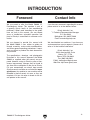
MOTOR
Wt
1L1 3L2 5L3
2T1 4T2 6T3
2T1 4T2 6T3
13no
14no
A2
98
A2
A1
97 96 95
Hot
Ground
Hot
BLACK
WHITE
GREEN
RED
BLUE
COLOR KEY
Bk
Wt
Gn
Rd
Bl
Ground
Hot
Hot
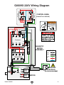
L6-20 PLUG
(as recommended)
220 VAC
CONTROL PANEL
(viewed from behind)
WARNING!
SHOCK HAZARD!
Disconnect power
before working on
wiring.
Gn
START
STOP
Rd
Rd
Rd
Rd Rd
Rd
Rd
Rd
Rd
Bl
Bl
Bk
Bk
Gn
Bk
Bk
Wt
Wt
Wt
MAGNETIC
SWITCH
ASSEMBLY
Contactor
Thermal Relay
Bk
Bk
Rd
Rd
Rd
Rd
Bl
Wt
Bk
Gn
Wt
Wt
Gn
Gn
Gn
Wt
Wt
Gn
Bk Wt
Bk
Gn
Wt
Wt
Rd
Rd
Rd
Rd
G0609X 220V Wiring Diagram

Model G0609X-4-
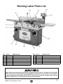
1
4
5
6
9
10
11
34
36
37
38
39
40
41
42
43
44
45
46
47
48
49
50
51
52
53
54
56
57
58
59
60
61
62
7
8
12
13
15
16
14
18
19
20
17
21
23
27
30
28
29
31
32
33
35
63
64
65
82
81
80
79
78
77
42-1
42-2
84
85
73
86
87
88
55-1
55
76
74
73
72
71
70
69
68
66
67
75
26
24
25
22
83
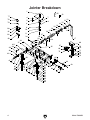
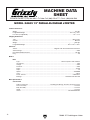
Jointer Breakdown

Model G0609X -5-
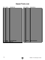
REF PART # DESCRIPTION REF PART # DESCRIPTION
1 P0609001 CUTTERHEAD GUARD 45 P0609045 SHAFT
4 PFH23M FLAT HD SCR M8-1.25 X 16 46 PLW06M LOCK WASHER 10MM
5 P0609005 SPECIAL FLAT WASHER 47 PB32M HEX BOLT M10-1.5 X 25
6 PSS04M SET SCREW M6-1 X 12 48 P0609048 BUSHING
7 P0609007 ADAPTER 49 P0609049 WORM GEAR
8 P0609008 TORSION SPRING 50 PK12M KEY 5 X 5 X 30
9 P0609009 SHAFT COLLAR 51 P0609051 GEAR
10 PSS04M SET SCREW M6-1 X 12 52 P0609052 WORM
11 P0609011 SHAFT 53 PK37M KEY 4 X 4 X 16
12 P0609012 CUTTERHEAD SCREW 54 P0609054 SLIDE STOP BLOCK
13 PLW06M LOCK WASHER 10MM 55 P0609055 SLIDE STOP BLOCK
14 PW04M FLAT WASHER 10MM 55-1 PSS16M SET SCREW M8-1.25 X 10
15 PK111 KEY 8 X 8 X 60 56 P0609056 SPECIAL FLAT SCREW
16 P0609016 CUTTERHEAD PULLEY 57 P0609057 POINTER
17 PVA53 V-BELT A-53 4L530 58 PW02M FLAT WASHER 5MM
18 PSB02M CAP SCREW M6-1 X 20 59 PS09M PHLP HD SCR M5-.8 X 10
19 P0609019 BEARING COVER 60 PB73M HEX BOLT M10-1.5 X 50
20 P6206 BALL BEARING 6206ZZ 61 P0609061 CLAMP BLOCK
21 P0609021 BEARING SUPPORT 62 PLW06M LOCK WASHER 10MM
22 P0452Z001 DRIVER BIT TORX T20 63 PW04M FLAT WASHER 10MM
23 P0609X023 SPIRAL CUTTERHEAD 12" 64 P0609064 CLAMPING BLOCK
24 P0452Z002 INDEXABLE INSERT 14 x 14 x 2 65 P0609065 CLAMP PLATE
25 P0452Z009 L-WRENCH TORX T20 66 PHTEK4M TAP SCREW M4 X 8
26 PFH35M FLAT HD TORX SCR T20 M6-1 X 15 67 P0609067 STOP BUTTON
27 P0609027 BEARING SUPPORT 68 P0609068 START BUTTON
28 P62042RZ BALL BEARING 62042RZ 69 P0609069 SWITCH BOX
29 PW01M FLAT WASHER 8MM 70 PFS14M FLANGE SCREW M8-1.25 X 16
30 P0609030 CUTTERHEAD SCREW 71 P0609071 SWITCH BOX BRACKET
31 PN02M HEX NUT M10-1.5 72 PB32M HEX BOLT M10-1.5 X 25
32 P0609032 BEARING COVER 73 PLW06M LOCK WASHER 10MM
33 PSB02M CAP SCREW M6-1 X 20 74 PW04M FLAT WASHER 10MM
34 PB156 HEX BOLT M10-1.5 X 150 75 P0609075 BUTTON PLATE
35 PSS71M SET SCREW M10-1.5 X 60 76 P0609076 BALL STRAIN RELIEF
36 P0609036 BASE 77 PAW10M HEX WRENCH 10MM
37 PSS04M SET SCREW M6-1 X 12 78 PAW08M HEX WRENCH 8MM
38 PW04M FLAT WASHER 10MM 79 PAW03M HEX WRENCH 3MM
39 P0609039 LOCK HANDLE 80 PWR1719 WRENCH 17 X 19
40 PSS03M SET SCREW M6-1 X 8 81 PWR1214 COMBO WRENCH 12/14MM
41 P0609041 ECCENTRIC BUSHING 82 PWR1012 COMBO WRENCH 10/12MM
42 P0609042 SHAFT 84 P0609084 BUSHING
42-1 P0609042-1 LEFT TORSION SPRING 85 P6202 BALL BEARING 6202ZZ
42-2 P0609042-2 RIGHT TORSION SPRING 86 PB06M HEX BOLT M8-1.25 X 12
43 P0609043 STOP BLOCK 87 PW03M FLAT WASHER 6MM
44 PR21M INT RETAINING RING 35MM 88 PB02M HEX BOLT M6-1 X 12
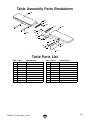
Jointer Breakdown Parts List

Model G0609X-6-
101
102
103
104
107
106
105
108
109
110
111
112
116
115
120
117
118
119
114
113
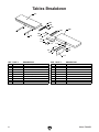
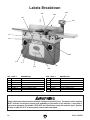
Tables Breakdown
REF PART # DESCRIPTION REF PART # DESCRIPTION
101 P0609101 TABLE (LEFT) 111 PSB72M CAP SCREW M10-1.5 X 30
102 P0609102 TABLE LIP (LEFT) 112 PLW06M LOCK WASHER 10MM
103 PLW06M LOCK WASHER 10MM 113 P0609113 DEPTH SCALE
104 PSB84M CAP SCREW M10-1.5 X 35 114 P0609114 RIVET 2 X 4
105 P0609105 SHAFT 115 PW03M FLAT WASHER 6MM
106 P0609106 TABLE (RIGHT) 116 PSB04M CAP SCREW M6-1 X 10
107 P0609107 TABLE LIP (RIGHT) 117 P0609117 DUST DEFLECTOR
108 PSB84M CAP SCREW M10-1.5 X 35 118 PSB38M CAP SCREW M5-.8 X 25
109 PLW06M LOCK WASHER 10MM 119 P0609119 STOP BLOCK
110 P0609110 RABBETING ARM 120 P0609120 BAR
Page is loading ...
Page is loading ...
Page is loading ...
Page is loading ...
Page is loading ...
Page is loading ...
Page is loading ...
Page is loading ...
Page is loading ...
Page is loading ...
Page is loading ...
Page is loading ...
Page is loading ...
Page is loading ...
Page is loading ...
Page is loading ...
Page is loading ...
Page is loading ...
Page is loading ...
Page is loading ...
Page is loading ...
Page is loading ...
Page is loading ...
Page is loading ...
Page is loading ...
Page is loading ...
Page is loading ...
Page is loading ...
Page is loading ...
Page is loading ...
Page is loading ...
Page is loading ...
Page is loading ...
Page is loading ...
Page is loading ...
Page is loading ...
Page is loading ...
Page is loading ...
Page is loading ...
Page is loading ...
Page is loading ...
Page is loading ...
Page is loading ...
Page is loading ...
Page is loading ...
Page is loading ...
Page is loading ...
Page is loading ...
Page is loading ...
Page is loading ...
Page is loading ...
Page is loading ...
Page is loading ...
Page is loading ...
Page is loading ...
Page is loading ...
Page is loading ...
Page is loading ...
Page is loading ...
Page is loading ...
Page is loading ...
Page is loading ...
Page is loading ...
Page is loading ...
Page is loading ...
Page is loading ...
-
 1
1
-
 2
2
-
 3
3
-
 4
4
-
 5
5
-
 6
6
-
 7
7
-
 8
8
-
 9
9
-
 10
10
-
 11
11
-
 12
12
-
 13
13
-
 14
14
-
 15
15
-
 16
16
-
 17
17
-
 18
18
-
 19
19
-
 20
20
-
 21
21
-
 22
22
-
 23
23
-
 24
24
-
 25
25
-
 26
26
-
 27
27
-
 28
28
-
 29
29
-
 30
30
-
 31
31
-
 32
32
-
 33
33
-
 34
34
-
 35
35
-
 36
36
-
 37
37
-
 38
38
-
 39
39
-
 40
40
-
 41
41
-
 42
42
-
 43
43
-
 44
44
-
 45
45
-
 46
46
-
 47
47
-
 48
48
-
 49
49
-
 50
50
-
 51
51
-
 52
52
-
 53
53
-
 54
54
-
 55
55
-
 56
56
-
 57
57
-
 58
58
-
 59
59
-
 60
60
-
 61
61
-
 62
62
-
 63
63
-
 64
64
-
 65
65
-
 66
66
-
 67
67
-
 68
68
-
 69
69
-
 70
70
-
 71
71
-
 72
72
-
 73
73
-
 74
74
-
 75
75
-
 76
76
-
 77
77
-
 78
78
-
 79
79
-
 80
80
-
 81
81
-
 82
82
-
 83
83
-
 84
84
-
 85
85
-
 86
86


Ask a question and I''ll find the answer in the document
Finding information in a document is now easier with AI
Related papers
-
Grizzly Biscuit Joiner G0609 User manual
-
-
-
-
Grizzly G0656W Owner's manual
-
-
Grizzly G0612 User manual
-
-
Shop fox Saw W1755 User manual
-
Other documents
-
King Canada KKC-60 User manual
-
PowerTec Pro BJ600 Owner's manual
-
-
Craftex CX Series CX06Z Owner's manual
-
Delta 37-071 User manual
-
-
Woodstock W1744H Owner's manual
-
Magnum MI-81350 Operating instructions
-
 South bend SB1091 Owner's manual
-
