York YPLC Technical Guide

Type
Technical Guide

York YPLC: A compact, energy-efficient gas furnace for residential and commercial applications, delivering reliable warmth and comfort. With its induced combustion, hot surface ignition, and high heat transfer aluminized tubular heat exchangers, it ensures efficient heating performance. Easily installed in upflow, horizontal, or downflow configurations, this versatile furnace adapts to various installation needs. Enjoy precise temperature control with its modulating heating operation, which allows for adjustments from 100% to 50% input in 1% increments.

York YPLC: A compact, energy-efficient gas furnace for residential and commercial applications, delivering reliable warmth and comfort. With its induced combustion, hot surface ignition, and high heat transfer aluminized tubular heat exchangers, it ensures efficient heating performance. Easily installed in upflow, horizontal, or downflow configurations, this versatile furnace adapts to various installation needs. Enjoy precise temperature control with its modulating heating operation, which allows for adjustments from 100% to 50% input in 1% increments.

TECHNICAL GUIDE
80% AFUE MODULATING ECM
RESIDENTIAL GAS FURNACES
MULTI-POSITION LOW NOx
MODELS: YPLC
NATURAL GAS
60 - 120 MBH INPUT
Due to continuous product improvement, specifications
are subject to change without notice.
Visit us on the web at:
www.york.com
Additional rating information can be found at:
www.ahridirectory.org
WARRANTY SUMMARY
A 20-year limited warranty on heat exchangers in residential
applications.
A 10-year warranty on the heat exchanger in commercial
applications.
Standard 5-year limited Parts warranty.
Extended residential limited lifetime heat exchanger and
10-year limited parts warranty when product is regis-
tered online within 90 days of purchase for replacement
or within 90 days of closing for new home construction.
See Limited Warranty certificate in Users Information Manual for details.
5425547-YTG-B-1217
FOR DISTRIBUTION USE ONLY - NOT TO BE USED AT POINT OF RETAIL SALE
DESCRIPTION
These compact units employ induced combustion, reliable hot
surface ignition and high heat transfer aluminized tubular heat
exchangers. The units are factory shipped for installation in
upflow or horizontal applications and may be converted for
downflow applications.
These furnaces are designed for residential installation in a
basement, closet, alcove, attic, recreation room or garage and
are also ideal for commercial applications. All units are factory
assembled, wired and tested to assure safe dependable and
economical installation and operation.
These units are Category I listed and may be common vented
with another gas appliance as allowed by the National Fuel Gas
Code.
FEATURES
Modulating heating operation includes:
- Modulating gas valve, inducer and circulating blower
- Modulating operation from 100% input to 50% input in 1%
increments or from 100% to 65% input with chimney kit
S1-1CK0605
Easily applied in upflow, horizontal left or right, or downflow
installation with minimal conversion necessary.
Compact, easy to install, ideal height 33" tall cabinet.
ECM variable speed motor for cooling SEER
enhancement, blower delay options for comfort, and
continuous fan options for IAQ performance.
Easy access to controls to connect power/control wiring.
24V, 40 VA control transformer and furnace control can be
conventionally wired to the OD unit for add-on cooling.
Furnace control connects with UPG communicating or
conventional thermostats.
Built-in, high level self diagnostics with fault code display.
Low unit current requirement for easy replacement
application.
All models are convertable to use propane (LP) gas.
Electronic Hot Surface Ignition saves fuel cost with
increased dependability and reliability.
100% shut off main gas valve for extra safety.
Hi-tech tubular aluminized steel primary heat exchanger.
Blower door safety switch.
Solid removable bottom panel allows easy conversion.
Low NOx models have been designed to meet specific
code requirements.
Airflow leakage less than 1% of nominal airflow for duct
performance testing conditions.
No knockouts to deal with, making installation easier.
Movable duct connector flanges for application flexibility.
Quiet inducer, burner and blower operation.
Inducer rotates for easy conversion of venting options.
Fully supported blower assembly for easy access and
removal of blower.
External air filters used for maximum flexibility in meeting
customers IAQ needs.
Venting applications - may be installed as a common vent
with other gas-fired appliances.
Insulated blower compartment for thermal and acoustic
performance.
1/4 turn knobs provided for easy door removal.
5425547-YTG-B-1217
2 Johnson Controls Unitary Products
NOTES:
Annual Fuel Utilization Efficiency (AFUE) numbers are determined in accordance with DOE Test procedures.
Wire size and over current protection must comply with the National Electrical Code (NFPA-70-latest edition) and all local codes.
/()76,'(
5,*+76,'(
´
´
5(7851(1'
%
´
´
´
(OHFWULFDO
(QWU\
*DV3LSH
(QWU\
7KHUPRVWDW
:LULQJ
)5217
´
´
´
´
6833/<(1'
&
´
´
´
%
*DV3LSH
(QWU\
7KHUPRVWDW
:LULQJ
´
$
´
(OHFWULFDO
(QWU\
9HQW&RQQHFWLRQ
2XWOHW
9HQW
&RQQHFWLRQ
2XWOHW
´'LDPHWHU
9HQW&RQQHFWLRQ
2XWOHW
$
Cabinet and Duct Dimensions
Models
Nominal
CFM (m
3
/min)
Cabinet
Size
Cabinet Dimensions (Inches)
ABC
YPLC060A12MP13C 1200 A 14.5 13.5 10.3
YPLC080B12MP13C 1200 B 17.5 16.5 11.8
YPLC080C16MP13C 1600 C 21 20 13.6
YPLC100C16MP13C 1600 C 21 20 13.6
YPLC100C20MP13C 2000 C 21 20 13.6
YPLC120C20MP13C 2000 C 21 20 15.8
Ratings & Physical / Electrical Data
Models
Input
Max/Min
Output
Max/Min
AFUE
Nominal
Airflow
Total
Unit
Amps
Air Temp. Rise
Max Input
Air Temp.
Rise Min Input
MBH MBH % CFM °F °F
YPLC060A12MP13C 60/30 47/24 80.0 1200 9.9 30-60 20-50
YPLC080B12MP13C 80/40 62/32 80.0 1200 9.9 40-70 20-50
YPLC080C16MP13C 80/40 62/32 80.0 1600 11.8 35-65 20-50
YPLC100C16MP13C 100/50 78/40 80.0 1600 11.8 35-65 20-50
YPLC100C20MP13C 100/50 78/40 80.0 2000 15.0 35-65 20-50
YPLC120C20MP13C 120/60 95/48 80.0 2000 15.0 45-75 25-55
Models
Max. Outlet
Air Temp
Blower
Blower
Wheel Size
Recommended
Fuse or
Circuit Breaker
Gas Pipe
Connection,
NPT
Approximate
Operating Weights
°F HP Amps Inches Amps Lbs
YPLC060A12MP13C 190 1/2 7.7 11 x 8 15 1/2" 94
YPLC080B12MP13C 190 1/2 7.7 11 x 8 15 1/2" 103
YPLC080C16MP13C 190 3/4 9.6 11 x 10 15 1/2" 114
YPLC100C16MP13C 190 3/4 9.6 11 x 10 15 1/2" 118
YPLC100C20MP13C 190 1 12.8 11 x 11 20 1/2" 122
YPLC120C20MP13C 190 1 12.8 11 x 11 20 1/2" 129
5425547-YTG-B-1217
Johnson Controls Unitary Products 3
FILTER PERFORMANCE
The airflow capacity data published in the “Blower Perfor-
mance” table represents blower performance WITHOUT filters.
All applications of these furnaces require the use of field
installed air filters. All filter media and mounting hardware or
provisions must be field installed external to the furnace cabi-
net. DO NOT attempt to install any filters inside the furnace.
NOTE: Single side return above 1800 CFM is approved as long
as the filter velocity does not exceed filter manufacturer’s rec-
ommendation and a transition is used to allow use of a 20” x 25”
filter.
NOTES:
1.Air velocity through throwaway type filters may not exceed 300 feet per min-
ute (91.4 m/min). All velocities over this require the use of high velocity fil-
ters.
2.Do not exceed 1800 CFM using a single side return and a 16x25 filter. For
CFM greater than 1800, you may use two side returns or one side and the
bottom or one return with a transition to allow use of a 20x25 filter.
ACCESSORIES
Propane (LP) Conversion Kit - This accessory conversion kit
may be used to convert natural gas units for LP operation.
Do not use Conversion Kit S1-1NP0680 with these models, as
the control/gas valve combination have been updated, and that
Kit S1-1NP0680 will not function correctly with these models.
S1-1NP0681 - All Models
LP Stainless Steel Burner Kit - This accessory conversion kit
may be used to convert existing burners to stainless steel burn-
ers for LP use only.
S1-32926889000 - All LP Models
Natural (NAT) Gas Stainless Steel Burner Kit - This acces-
sory kit may be used to replace existing burners with stainless
steel burners for NAT gas use only.
S1-32924441000 - All NAT gas Models
Side Return Filter Racks - The S1-1SR0200 Kit accommo-
dates a 1”, 2” or 4” filter. The S1-1SR0402 Kit accommodates a
1” filter only.
S1-1SR0200 - All Models
S1-1SR0402 - All Models
Bottom Return Filter Racks - The S1-1BR05* series are gal-
vanized steel filter racks. The S1-1BR06* series are pre-painted
steel filter racks to match the appearance of the furnace cabi-
net. The S1-1BR05* and S1-1BR06* series filter racks accom-
modate a 1”, 2” or 4” filter.
S1-1BR0514 or S1-1BR0614 - For 14-1/2” cabinets
S1-1BR0517 or S1-1BR0617 - For 17-1/2” cabinets
S1-1BR0521 or S1-1BR0621 - For 21” cabinets
Masonry Chimney Kit - This accessory kit allows the 80%
modulating upflow models to be vented into a tile-lined masonry
chimney.
S1-1CK0605 - All 80% Modulating Models
Combustible Floor Base Kit - These kits are required to pre-
vent potential overheating situations when the furnaces are
installed in downflow applications directly onto combustible
flooring material. These kits are also required in any applica-
tions where the furnace is installed in a downflow configuration
without an indoor coil and where the combustible floor base kit
provides access for combustible airflow.
S1-1CB0514 - For 14-1/2” cabinets
S1-1CB0517 - For 17-1/2” cabinets
S1-1CB0521 - For 21” cabinets
High Altitude - No high altitude kits are required.
Thermostats - Compatible thermostat controls are available
through accessory sourcing. For optimum performance, these
units are fully compatible with our York touch screen thermostat
with proprietary (patent-pending) hexagon interface. For more
information, see the thermostat section of the Product Equip-
ment Catalog.
S1-THXU280 - All Models
CAUTION
In horizontal furnace arrangement, the filter must be located a mini-
mum of 12” from the return air inlet of furnace.
In downflow furnace arrangement, the filter must be located a mini-
mum of 36” from the return air inlet of furnace.
!
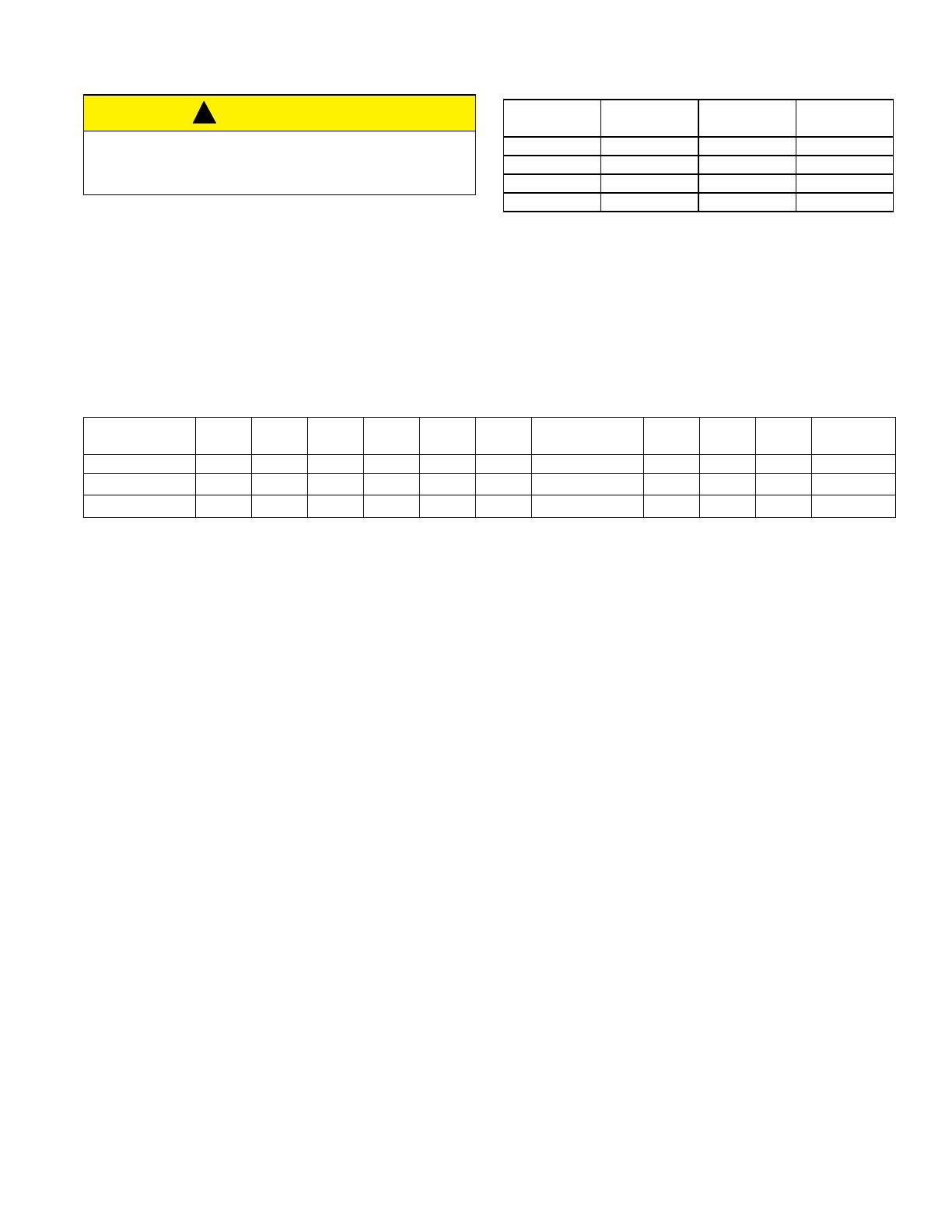
Recommended Filter Sizes
CFM
Cabinet
Size
Side
(in)
Bottom
(in)
1200 A 16 x 25 14 x 25
1200 B 16 x 25 16 x 25
1600 C 16 x 25 20 x 25
2000 C (2) 16 x 25 20 x 25
Unit Clearances to Combustibles
Application Top Front Rear
Left
Side
Right
Side
Flue
Floor/
Bottom
Closet Alcove Attic
Line
Contact
Upflow B-Vent 130001Combustible Yes Yes Yes No
Downflow B-Vent 130001
1
1
1. Special floor base or air conditioning coil required for use on combustible floor.
Yes Yes Yes No
Horizontal B-Vent 130001Combustible No Yes Yes
Yes
2
2. Line contact only permitted between lines formed by the intersection of the rear panel and side panel (top in horizontal position) of the furnace jacket and building
joists, studs or framing.
NOTES:
Subject to change without notice. Published in U.S.A. 5425547-YTG-B-1217
Copyright © 2017 by Johnson Controls, Inc. All rights reserved. Supersedes: 5425547-YTG-A-0917
York International Corp.
5005 York Drive
Norman, OK 73069
NOTES:
All CFM’s are shown at 0.5” w.c. external static pressure.These units have variable speed motors that automatically adjust to provide constant CFM from 0.0”
to 0.6” w.c. static pressure. From 0.6” to 1.0” static pressure, CFM is reduced by 2% per 0.1” increase in static. Operation on duct systems with greater than
1.0” w.c. external static pressure is not recommended.
At some settings, LOW COOL airflow may be lower that what is required to operate an airflow switch on certain models of electronic air cleaners. Consult the
instructions for the electronic air cleaner for further details.
Blower Performance CFM - Any Position
High / Low Speed Cooling CFM
060A12 080B12 080C16 Jumper Settings
HIGH COOL LOW COOL HIGH COOL LOW COOL HIGH COOL LOW COOL COOL Jumper ADJ Jumper
1277 825 1241 834 1644 1054 H B
1067 709 1064 720 1447 927 MH B
1162 762 1147 782 1489 955 H A
972 667 960 678 1321 857 MH A
1046 699 1043 709 1349 871 H C
857 615 855 605 1236 815 ML B
888 615 866 615 1166 787 MH C
678 499 678 501 1012 703 L B
783 573 793 563 1096 759 ML A
625 478 626 459 927 660 L A
720 531 720 521 998 703 ML C
583 478 574 459 843 604 L C
100C16 100C20 120C20 Jumper Settings
HIGH COOL LOW COOL HIGH COOL LOW COOL HIGH COOL LOW COOL COOL Jumper ADJ Jumper
1674 1069 2178 1545 2232 1446 H B
1463 943 1870 1339 1783 1203 MH B
1519 971 2126 1459 2026 1334 H A
1336 858 1716 1254 1615 1091 MH A
1378 1013 1938 1339 1839 1203 H C
1238 816 1647 1220 1540 1054 ML B
1168 788 1562 1168 1446 979 MH C
1027 690 1459 1100 1353 904 L B
1111 760 1528 1151 1409 960 ML A
929 633 1374 1049 1222 848 L A
1013 676 1425 1066 1297 867 ML C
844 591 1288 997 1147 773 L C
  • Page 1 1
  • Page 2 2
  • Page 3 3
  • Page 4 4

York YPLC Technical Guide

Type
Technical Guide

York YPLC: A compact, energy-efficient gas furnace for residential and commercial applications, delivering reliable warmth and comfort. With its induced combustion, hot surface ignition, and high heat transfer aluminized tubular heat exchangers, it ensures efficient heating performance. Easily installed in upflow, horizontal, or downflow configurations, this versatile furnace adapts to various installation needs. Enjoy precise temperature control with its modulating heating operation, which allows for adjustments from 100% to 50% input in 1% increments.

Ask a question and I''ll find the answer in the document

Finding information in a document is now easier with AI