
4-540-680-14 (1)
© 2014 Sony Corporation
Data
Projector
Operating Instructions
Before operating the unit, please read this manual and supplied Quick Reference Manual
thoroughly and retain it for future reference.
VPL-EW295/EW255/EW235
VPL-EX295/EX290/EX255/EX250/EX235/EX230
Not all models are available in all countries and area. Please check
with your local Sony Authorized Dealer.

2
Table of Contents
Table of Contents
Overview
Location and Function of Controls .... 4
Main Unit .....................................4
Terminal .......................................5
Remote Commander and Control
Panel Keys ................................. 6
Preparation
Connecting the Projector ................... 9
Connecting a Computer ................9
Connecting a Video
equipment ................................ 11
Connecting a microphone .......... 13
Connecting a USB memory
device ...................................... 13
Connecting an External Monitor and
Audio Equipment ....................14
Projecting/Adjusting an
Image
Projecting an Image ......................... 15
Adjusting the Projected image ... 16
Turning Off the Power ................ 19
Adjustments and Settings
Using a Menu
Using a MENU ................................ 20
The Picture Menu .............................21
The Screen Menu .............................22
The Function Menu .......................... 26
The Operation Menu ........................ 27
The Connection/Power Menu .......... 28
The Installation Menu ......................30
The Information Menu .....................31
Network
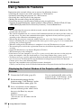
Using Network Features ...................32
Displaying the Control Window of
the Projector with a Web
Browser ...................................32
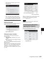
Confirming the Information
regarding the Projector ............33
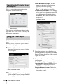
Operating the Projector from a
Computer .................................34
Using the e-mail report
Function ...................................34
Setting the LAN Network of the
projector ..................................35
Setting the WLAN Network of the
projector ..................................35
Setting the Custom Labels for the
Input Terminals of the
Projector ..................................38
Setting the Control Protocol of the
Projector ..................................38
Presentation Function via
Network
Using Presentation Function via
Network .........................................42
Installing Projector Station for
Network Presentation ..............42
Starting Projector Station for
Network Presentation ..............42
Projecting an Image ....................43
Connection Settings ....................44
Using the Controller ...................44

3
Table of Contents
Displaying Images or Files Sent
from a Tablet
PC/Smartphone .......................45
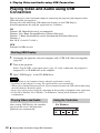
Playing Video and Audio
using USB Connection
Playing Video and Audio using USB
Connection ....................................46
Starting USB Display .................46
Playing Video and Audio ...........46
Using the Controller ...................46
USB Media Viewer
Using USB Media Viewer ................48
Thumbnail Mode ........................49
Option Menu ...............................49
Display Mode .............................50
Option Menu ...............................50
Slideshow Mode .........................50
Option Menu ...............................51
Others
Indicators ..........................................52
Messages List ...................................53
Troubleshooting ...............................54
Replacing the Lamp .........................56
Cleaning the Air Filter .....................58
Specifications ...................................59
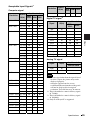
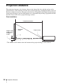
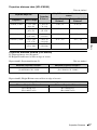
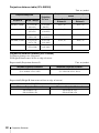
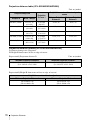
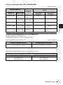
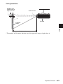
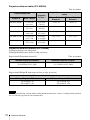
Projection Distance ..........................66
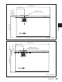
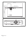
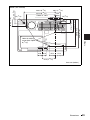
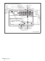
Dimensions .......................................80
END USER LICENSE
AGREEMENT ..............................86
Index .................................................92

4
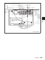
Location and Function of Controls
B Overview
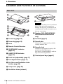
Location and Function of Controls
a Focus ring (page 16)
b Zoom ring (page 16)
c Lens
d Remote Control Receiver
e ON/STANDBY indicator
(page 52)
f LAMP/COVER indicator
(page 52)
g Front feet (adjustable) (page 17)
h Foot adjust button (page 17)
i Air filter cover/Ventilation holes
(intake) (page 58)
j Lamp cover (page 56)
k Ventilation holes (exhaust)
Do not place anything near the ventilation
holes as this may cause internal heat
buildup. Do not place your hand near the
ventilation holes and the circumference as
this may cause injury.
l Speaker (VPL-EW295/EW255/
EW235/EX295/EX255/EX235
only)
m Terminal (page 5)
n Security bar
Connects to a commercially available
security chain or wire.
o Security lock
Connects to an optional security cable
manufactured by Kensington.
For details, visit Kensington’s web site.
http://www.kensington.com/
p Control panel keys (page 6)
Main Unit
5
4
3
2
1
6
8
7
9
qa
qs
7
8
0
Caution
qh
qf
qd
q
g

5
Location and Function of Controls
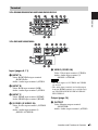
Overview
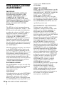
VPL-EW295/EW255/EW235/EX295/EX255/EX235
VPL-EX290/EX250/EX230
Input (pages 9, 11)
a INPUT A
Video: RGB/YPBPR input terminal
(RGB/YP
BPR)
Audio: Audio input terminal (AUDIO)
b INPUT B
Video: RGB input terminal (RGB)
Audio: Audio input terminal (AUDIO)
c INPUT C
Video: HDMI input terminal (HDMI)
Audio: HDMI input terminal (HDMI)
d S VIDEO (S VIDEO IN)
Video: S video input terminal (S VIDEO
IN)
Audio: Audio input terminal (L
(MONO) AUDIO/R)
e VIDEO (VIDEO IN)
Video: Video input terminal (VIDEO)
Audio: Audio input terminal (L
(MONO) AUDIO/R)
• The audio inputs of S VIDEO and VIDEO
are shared.
• The audio input terminal and audio output
from the HDMI terminal are available only
on VPL-EW295/EW255/EW235/EX295/
EX255/EX235.
Output (page 14)
f OUTPUT
Video: Monitor output terminal
(MONITOR)
Audio: Audio output terminal (AUDIO)
Terminal
54
4
5
7
6
1
29
8q;3
qs
qa
54
7
6
1
29
8q;3qa
Notes

6
Location and Function of Controls
• This terminal outputs the projected image
only when INPUT A or INPUT B is used.
• The audio output terminal is available only
on VPL-EW295/EW255/EW235/EX295/
EX255/EX235.
Others
g RS-232C terminal (RS-232C)
RS-232C compatible control terminal.
Connects the computer’s RS-232C
terminal and the RS-232C cross cables.
h LAN terminal (page 32)
i AC IN (∼) socket
Connects the supplied AC power cord.
j USB terminal (Type A) ( )
(pages 13, 48)
k USB terminal (Type B) ( )
(page 46)
l Microphone input ( )
Microphone input is available only on VPL-
EW295/EW255/EW235/EX295/EX255/
EX235.
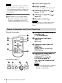
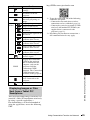
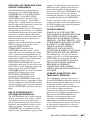
Remote Commander
Control Panel Keys
a Turning on the power/Going to
standby mode
?/1 (On/Standby) key
b Selecting an input signal
(page 15)
INPUT key
c Operating a menu (page 20)
MENU key
RESET key
ENTER /V/v/B/b (arrow) keys
RETURN key
d Adjusting the image (page 16)
ASPECT key (page 22)
KEYSTONE key (page 18)
PATTERN key (page 18)
APA (Auto Pixel Alignment) key
*
(page 18)
*
Use this key when inputting a computer
signal via the RGB input terminal
(INPUT A or INPUT B).
Notes
Note
Remote Commander and Control Panel Keys
2
3
4
5
6
1
4
7
INPUT
MENU
APA ECO MODE
RETURN
ASPECT
D ZOOM
KEYSTONE
ENTER
VOLUME
PATTERN
FREEZE
BLANK
MUTING
RESET
3
6
12
Note

7
Location and Function of Controls
Overview
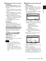
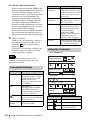
e Using various functions during
projecting
D ZOOM (Digital Zoom) +/– key
*1
Enlarges a portion of the image while
projecting.
1 Press the D ZOOM + key to display
the digital zoom icon on the projected
image.
2 Press the V/v/B/b keys to move the
digital zoom icon to the point on the
image you want to enlarge.
3 Press the D ZOOM + key or the D
ZOOM – key repeatedly to change the
enlargement ratio. The image can be
enlarged up to 4 times.
Press the RESET key to restore the
previous image.
BLANK key
Cuts off the projected image
temporarily. Press again to restore the
previous image. Picture muting helps
reduce power consumption.
MUTING key (VPL-EW295/EW255/
EW235/EX295/EX255/EX235 only)
Mutes the audio output temporarily.
Press again to restore the previous
volume.
VOLUME +/– key (VPL-EW295/
EW255/EW235/EX295/EX255/
EX235 only)
Adjusts the volume output.
FREEZE key
*2
Pauses a projected image. Press again to
restore the image.
*1: Use this key when inputting a
computer signal. But it may not be
used depending on the resolution of
the input signal.
*2: Use this key when inputting a
computer signal.You cannot use this
key when
“Type A USB”, “Type B
USB
” or “Network” is selected as the
input.
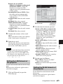
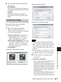
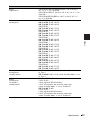
f Setting the energy–saving mode
easily
ECO MODE key
Energy-saving mode can be set easily.
Energy-saving mode consists of “Lamp
Mode,” “With No Input,” “With Static
Signal” and “Standby Mode.”
1 Press the ECO MODE key to display
the ECO Mode menu.
2 Press the V/v key or ECO MODE key
to select “ECO” or “User” mode.
ECO: Sets each mode to the optimum
energy-saving value.
Lamp Mode: Low
With No Input: Standby
With Static Signal: Lamp
Dimming
Standby Mode: Low
User: Sets each item of the ECO
Mode menu as you desire (go to
step 3).
3 Select “User” then press the b key.
The setting items appear.
4 Press the V/v key to select the item
then press the ENTER key.
5 Press the V/v key to select the setting
value.
6 Press the ENTER key.
The screen returns to the User screen.
For details on ECO Mode settings, see
“Lamp Mode,” “With No Input,” “With
Static Signal” and “Standby Mode” on
the Connection/Power menu (page 28).
Notes
RETURN
ECO
User
ECO Mode
:Sel
:Back
RETURN
Lamp Mode High
Constant Brightness
Auto Power Saving
Standby Mode
Off
ON
With No Input
Lamp Dimming
With Static Signal
Standard
User
:S el
:S et
:Back

8
Location and Function of Controls
If you set “ECO Mode” to “ECO,” or
“Standby Mode”(in “User”) to “Low,”
the network control function will be
disabled in standby mode. If the external
control is being performed by using the
network or network control function, do
not select “ECO,” or do not set “Standby
Mode” ( in “User”) to “Low.”
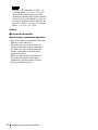
Others
g Infrared transmitter
About remote commander operation
• Direct the remote commander toward the
Remote Control Receiver.
• The shorter the distance between the
remote commander and the projector is,
the wider the angle within which the
remote commander can control the
projector becomes.
• Make sure that nothing obstructs the
infrared beam between the remote
commander and the Remote Control
Receiver on the projector.
Note

9
Connecting the Projector
Preparation
B Preparation
Connecting the Projector
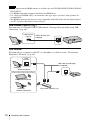
• Make sure all the equipment is powered off when connecting the projector.
• Use the proper cables for each connection.
• Insert the cable plugs firmly; Loose connections may reduce performance of picture signals or
cause a malfunction. When pulling out a cable, be sure to grip it by the plug, not the cable itself.
• For more information, refer also to the instruction manuals of the equipment you are connecting.
• Use a no-resistance audio cable.
Connection with a computer is explained for each input signal.
INPUT A/INPUT B
• The audio input terminal is available only on VPL-EW295/EW255/EW235/EX295/EX255/
EX235.
• It is recommended that you set the resolution of your computer to 1280 × 800 pixels (VPL-EW295/
EW255/EW235) or 1024 × 768 pixels (VPL-EX295/EX290/EX255/EX250/EX235/EX230) for
the external monitor.
INPUT C
Notes
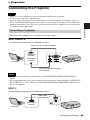
Connecting a Computer
For connecting a computer with an RGB output terminal.
RGB output
terminal
Audio output
terminal
Mini D-sub 15-pin cable (supplied)
Computer
Audio cable (Stereo mini plug)
(not supplied)
Notes
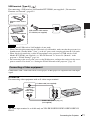
For connecting a computer with an HDMI output terminal.
HDMI output
terminal
HDMI cable
(not supplied)
Computer

10
Connecting the Projector
• Audio output from the HDMI terminal is available only on VPL-EW295/EW255/EW235/EX295/
EX255/EX235.
• Use HDMI-compatible equipment which has the HDMI Logo.
• Use a high speed HDMI cable(s) on which the cable type logo is specified. (Sony products are
recommended.)
• The HDMI terminal of this projector is not compatible with DSD (Direct Stream Digital) Signal
or CEC (Consumer Electronics Control) Signal.
USB terminal (Type B) ( )
For connecting to a computer with a USB terminal (“Playing Video and Audio using USB
Connection” (page 46)).
LAN terminal
For connecting to a computer, tablet PC, or smartphone via a hub or router (“Presentation
Function via Network” (page 42)).
Notes
USB A-B cable (not
supplied)
Computer
USB terminal
(Type A)
LAN cable (straight type)
(not supplied)
Computer
LAN
terminal
Wired connection
Tablet PC/Smartphone
Computer
Wireless connection
Hub, router (wireless), etc.

11
Connecting the Projector
Preparation
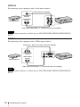
USB terminal (Type A) ( )
For connecting a USB wireless LAN module IFU-WLM3 (not supplied) (“Presentation
Function via Network” (page 42)).
• Undesignated USB wireless LAN modules do not work.
• When connecting/disconnecting the USB wireless LAN module, make sure that the projector is in
Standby mode (Standby Mode: “Low”), or the AC power cord is unplugged from the wall outlet.
• When wirelessly connecting a tablet PC/smartphone to the projector via USB wireless LAN
Module IFU-WLM3 (not supplied), set “WLAN Network” to “Access Pt. (Manual)” in the
projector’s “WLAN Settings” (page 28).
• For connecting to the access point, access to the Web browser, and input the settings for the access
point to connect. For details, see “Setting the WLAN Network of the projector” (page 35).
Connections with a VHS video deck, DVD player, or BD player are explained for each input
signal.
S VIDEO IN
For connecting video equipment with an S-video output terminal.
The audio input terminal is available only on VPL-EW295/EW255/EW235/EX295/EX255/
EX235.
Notes
Connecting a Video equipment
USB wireless LAN module
IFU-WLM3 (not supplied)
Tablet PC/Smartphone
Computer
Wireless router, access
point
Note
S video output
terminal
Audio output
terminal
S video cable (not supplied)
Computer
Audio cable (Phono plug × 2)
(not supplied)

12
Connecting the Projector
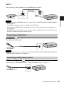
VIDEO IN
For connecting video equipment with a video output terminal.
The audio input terminal is available only on VPL-EW295/EW255/EW235/EX295/EX255/
EX235.
INPUT A
For connecting video equipment with a YPBPR output terminal.
The audio input terminal is available only on VPL-EW295/EW255/EW235/EX295/EX255/
EX235.
Note
Note
Video cable (not supplied)
Audio cable (Phono plug × 2 – stereo mini plug) (not supplied)
Video output
terminal
Audio output
terminal
Video equipment
Component – Mini D-sub 15-pin cable (not supplied)
Audio cable (Phono plug × 2 – stereo mini plug) (not supplied)
Video equipment
YP
BPR output
terminal
Audio output
terminal

13
Connecting the Projector
Preparation
INPUT C
• Audio output from the HDMI terminal is available only on VPL-EW295/EW255/EW235/EX295/
EX255/EX235.
• Use HDMI-compatible equipment which has the HDMI Logo.
• Use a high speed HDMI cable(s) on which the cable type logo is specified. (Sony products are
recommended.)
• The HDMI terminal of this projector is not compatible with DSD (Direct Stream Digital) Signal
or CEC (Consumer Electronics Control) Signal.
Microphone ( )
For connecting a microphone.
• The microphone input is available only on VPL-EW295/EW255/EW235/EX295/EX255/EX235.
• Only dynamic microphones are supported.
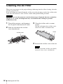
USB terminal (Type A) ( )
For connecting a USB memory device (“Using USB Media Viewer” (page 48)).
Notes
Connecting a microphone
Notes
Connecting a USB memory device
Video equipment
HDMI cable
(not supplied)
HDMI output
terminal
For connecting video equipment with an HDMI output terminal.
Microphone
(not supplied)
USB memory device
(not supplied)

14
Connecting the Projector
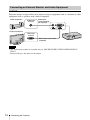
OUTPUT
Projected images or input audio can be output to display equipment such as a monitor or audio
equipment such as speakers with a built-in amplifier.
• The audio input terminal is available only on VPL-EW295/EW255/EW235/EX295/EX255/
EX235.
• Projected images and audio can be output.
Connecting an External Monitor and Audio Equipment
Notes
Audio cable
(stereo mini plug)
(not supplied)
Audio input
terminal
Mini D-sub 15-pin cable
(supplied)
RGB input
terminal
Audio equipment
Display equipment

15
Projecting an Image
Projecting/Adjusting an Image
B Projecting/Adjusting an Image
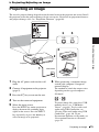
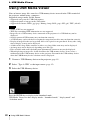
Projecting an Image
The size of a projected image depends on the distance between the projector and screen. Install
the projector so that the projected image fits the screen size. For details on projection distances
and projected image sizes, see
“Projection Distance” (page 66).
1 Plug the AC power cord into the wall
outlet.
2 Connect all equipment to the projector
(page 9).
3 Press the ?/1 key to turn on the unit.
4 Turn on the connected equipment.
5 Select the input source.
Press the INPUT key on the projector to
display the menu for switching input
signal on the screen. Press the INPUT
key repeatedly, or press the
V/v key to
select an image to be projected.
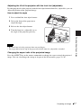
6 When projecting a computer image,
switch your computer’s output to
external display.
The method to switch the output varies
depending on the type of computer.
(Example)
To project image files stored in a USB
memory device, see “USB Media
Viewer” (page 48). To play video and
audio using USB Connection, see
“Playing Video and Audio using USB
Connection” (page 46). To use
Presentation Function via Network, see
“Presentation Function via Network”
(page 42).
Computer
Video equipment
Projector
Wall outlet
1
2
5
4
3
6
+


17
Projecting an Image
Projecting/Adjusting an Image
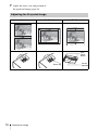
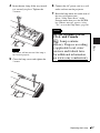
Adjusting the tilt of the projector with the front feet (adjustable)
By changing the tilt of the projector with the foot adjust buttons/front feet (adjustable), you can
adjust the position of the projected image.
How to adjust the angle
1 Press and hold the foot adjust buttons.
2 Lift up the front of the projector to
adjust the angle.
3 Release the foot adjust buttons.
4 Turn the front feet (adjustable) to set
the angle of the projector precisely.
• Be careful not to let the projector down on your fingers.
• Do not push hard on the top of the projector with the front feet (adjustable) extended.
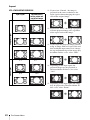
Changing the aspect ratio of the projected image
Press the ASPECT key on the remote commander to change the aspect ratio of the projected
image. You can also change the setting in Aspect of the Screen menu (pages 22, 24).
Notes

18
Projecting an Image
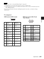
Correcting trapezoidal distortion of the projected image (Keystone feature)
Normally the Keystone feature automatically adjusts the projected image. The Keystone
feature may not work automatically if the screen is tilted. In this case, set Keystone manually.
1 Press the KEYSTONE key on the remote
commander or select V Keystone in the
Installation menu.
2 Use the V/v/B/b keys to set the value. The
higher the value, narrower the top of the
projected image. The lower the value, the
narrower the bottom.
Since the Keystone adjustment is an electronic
correction, the image may be deteriorated.
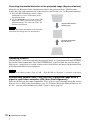
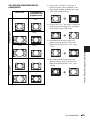
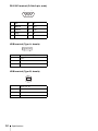
Displaying a pattern
You can display a pattern for adjusting the projected image or a grid pattern with the PATTERN
key on the remote commander. Press the PATTERN key again to restore the previous image.
You can use a grid pattern as a guide to write text or to draw lines and shapes on the whiteboard
or blackboard without using a computer.
You cannot use this key when “Type A USB”, “Type B USB” or “Network” is selected as the input.
Automatically adjusts Phase, Pitch and Shift of projected image while a
signal is input from a computer (APA (Auto Pixel Alignment))
Press the APA key on the remote commander. Press again to cancel adjusting during the setting.
You can also set APA in the Screen Menu (page 23). If Smart APA in the Function menu is set
to “On”, executes APA automatically when a signal is input (page 26).
Note
Increase the number
towards plus
Increase the number
towards minus
Note

19
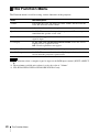
Projecting an Image
Projecting/Adjusting an Image
1 Press the ?/1 key on the unit or the remote commander.
The projector starts shutdown and turns off. If you press the ?/1 key within 10 seconds
again, shutdown is cancelled.
Do not turn off the projector soon after the lamp lights. It may cause a malfunction of the lamp
(does not light ,etc.).
2 Unplug the AC power cord from the wall outlet.
To turn off without displaying confirmation message
Press and hold the ?/1 key on the unit for a few seconds (page 53).
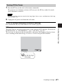
ECO gauge
This gauge indicates the current effectiveness of the projector’s ECO function. (For details on
the ECO function, see “ECO MODE key” (page 7) and “ECO” (page 28).)
The leaf icons are displayed when the projector is shut down. The number of displayed icons
varies according to how much energy is saved as a result of using the ECO function.
Turning Off the Power
Note
ECO gauge

20
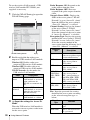
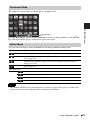
Using a MENU
B Adjustments and Settings Using a Menu
Using a MENU
The menu displays used for the explanation below may be different depending on the model you are
using.
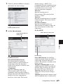
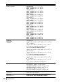
1 Press the MENU key to display the
menu.
2 Select the setting menu.
Use the V/v key to select the setting
menu then press the b key or ENTER
key.
3 Select the setting item.
Use the V/v key to select the setting
menu then press the b key or ENTER
key.
To return to the selection screen of the
setting menu, press the B or RETURN
key.
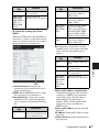
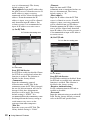
4 Make the setting or adjustment for the
selected item.
The setting method varies, depending on
the setting item.
If the next menu window is displayed,
select the item according to the
operations in step 3 and then press the
ENTER key to register the setting.
To return to the selection screen of the
setting items, press the B or RETURN
key. You can press the RESET key to
reset an item to its factory setting value
to aid setting.
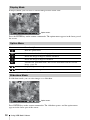
Using a pop-up menu
Press the V/v/B/b key to select an item.
A selected item takes effect
immediately, except “Language”, which
will take effect after you press the
ENTER key.
Using the setting menu
Press the V/v key to select the item.
Press the ENTER key to register the
setting and return to the previous screen.
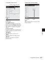
Using the adjustment menu
To increase the value, press the V/b key
and to decrease the number, press the
v/B key. Press the ENTER key to
register the setting and return to the
previous screen.
5 Press the MENU key to clear the
menu.
The menu disappears automatically if no
operation is performed.
Note
Picture Mode Standard
Reset
Contrast
Brightness
Color
Hue
Color Temp.
Sharpness
Expert Setting
:S el :Set :Back
Picture
Low
Setting menu
80
50
50
50
5
Picture Mode Standard
Reset
Contrast
Brightness
Color
Hue
Color Temp.
Sharpness
Expert Setting
:S el :Set :Back
Picture
Low
Setting items
RETURN
Picture Mode
Dynamic
Standa rd
:Back
:S el
Cinema
Whiteboa rd
Blackboard
Presentation
Adjust
Back
Contrast
Page is loading ...
Page is loading ...
Page is loading ...
Page is loading ...
Page is loading ...
Page is loading ...
Page is loading ...
Page is loading ...
Page is loading ...
Page is loading ...
Page is loading ...
Page is loading ...
Page is loading ...
Page is loading ...
Page is loading ...
Page is loading ...
Page is loading ...
Page is loading ...
Page is loading ...
Page is loading ...
Page is loading ...
Page is loading ...
Page is loading ...
Page is loading ...
Page is loading ...
Page is loading ...
Page is loading ...
Page is loading ...
Page is loading ...
Page is loading ...
Page is loading ...
Page is loading ...
Page is loading ...
Page is loading ...
Page is loading ...
Page is loading ...
Page is loading ...
Page is loading ...
Page is loading ...
Page is loading ...
Page is loading ...
Page is loading ...
Page is loading ...
Page is loading ...
Page is loading ...
Page is loading ...
Page is loading ...
Page is loading ...
Page is loading ...
Page is loading ...
Page is loading ...
Page is loading ...
Page is loading ...
Page is loading ...
Page is loading ...
Page is loading ...
Page is loading ...
Page is loading ...
Page is loading ...
Page is loading ...
Page is loading ...
Page is loading ...
Page is loading ...
Page is loading ...
Page is loading ...
Page is loading ...
Page is loading ...
Page is loading ...
Page is loading ...
Page is loading ...
Page is loading ...
Page is loading ...
Page is loading ...
Page is loading ...
-
 1
1
-
 2
2
-
 3
3
-
 4
4
-
 5
5
-
 6
6
-
 7
7
-
 8
8
-
 9
9
-
 10
10
-
 11
11
-
 12
12
-
 13
13
-
 14
14
-
 15
15
-
 16
16
-
 17
17
-
 18
18
-
 19
19
-
 20
20
-
 21
21
-
 22
22
-
 23
23
-
 24
24
-
 25
25
-
 26
26
-
 27
27
-
 28
28
-
 29
29
-
 30
30
-
 31
31
-
 32
32
-
 33
33
-
 34
34
-
 35
35
-
 36
36
-
 37
37
-
 38
38
-
 39
39
-
 40
40
-
 41
41
-
 42
42
-
 43
43
-
 44
44
-
 45
45
-
 46
46
-
 47
47
-
 48
48
-
 49
49
-
 50
50
-
 51
51
-
 52
52
-
 53
53
-
 54
54
-
 55
55
-
 56
56
-
 57
57
-
 58
58
-
 59
59
-
 60
60
-
 61
61
-
 62
62
-
 63
63
-
 64
64
-
 65
65
-
 66
66
-
 67
67
-
 68
68
-
 69
69
-
 70
70
-
 71
71
-
 72
72
-
 73
73
-
 74
74
-
 75
75
-
 76
76
-
 77
77
-
 78
78
-
 79
79
-
 80
80
-
 81
81
-
 82
82
-
 83
83
-
 84
84
-
 85
85
-
 86
86
-
 87
87
-
 88
88
-
 89
89
-
 90
90
-
 91
91
-
 92
92
-
 93
93
-
 94
94


Ask a question and I''ll find the answer in the document
Finding information in a document is now easier with AI
Related papers
-
Sony VPL-EX250 Operating instructions
-
Sony Sony VPL-DX146 User manual
-
Sony VPL-EW130 User manual
-
Sony VPL-CX20A User manual
-
Sony Sony VPL-FHZ55B User manual
-
Sony VPL-DS100 User manual
-
Sony UBP-X700 License
-
Sony VPL-DX126 Specification
-
Sony BrightEra VPL-FH35 Operating Instructions Manual
-
Sony VPL-VW365 Quick start guide
Other documents
-
Canon WUX450 User manual
-
Anthem LTX 300 User manual
-
EZ-ACCESS Passport Installation guide
-
Panasonic PT-ST10E Datasheet
-
-
Abtus AVS-320 User's Operation Manual
-
Toshiba EX250 User manual
-
OJ Electronics WLTA3 Installation guide
-
-
Sierra Monitor Corporation EX250-SEN1 User manual