
261
PO
(261PO) Sand Filter Pump & Saltwater System with E.C.O. ENGLISH 7.5” X 10.3” PANTONE 295U 07/23/2014
English
Sand Filter Pump &
Saltwater System with E.C.O.
(Electrocatalytic Oxidation)
Model ECO 20110 & 15110
IMPORTANT
SAFETY RULES
Read, understand, and follow
all instructions carefully before
installing and using this product.
Don’t forget to try these other fine Intex products: pools, pool
accessories, inflatable pools and in-home toys, airbeds and boats
available at fine retailers or visit our website.
Due to a policy of continuous product improvement, Intex reserves the
right to change specifications and appearance, which may result in
updates to the instruction manual without notice.
OWNER’S MANUAL
For illustrative purposes only.
IMPORTANT!
DO NOT RETURN PRODUCT TO STORE
To purchase parts and accessories or to obtain non-technical assistance, Visit
www.intexcorp.com
For technical assistance and missing parts call us toll-free (for U.S. and Canadian Residents):
1-800-234-6839
Monday through Friday, 8:30am to 5:00pm Pacific Time
261-*PO-R0-1507

261
PO
(261PO) Sand Filter Pump & Saltwater System with E.C.O. ENGLISH 7.5” X 10.3” PANTONE 295U 07/23/2014
English
SAVE THESE INSTRUCTIONS
Page 2
Warnings
........................................................................................
3
Parts References
.............................................................. ............
4-5
Setup Instructions
.......................................................................
6-13
Product Specifications
.................................................................
8
Operating Instructions
................................................................
14-18
LED Code Chart
............................................................................
19
Salt & Pool Water Volumes
..........................................................
20
Intex Pools Salt Table
........................................................... ........
21
Intex Pools Cyanuric Acid Table
.................................................
22
Intex Pools Operating Time Table
..............................................
23
Non-Intex Pools Salt Table
...........................................................
24
Non-Intex Pools Cyanuric Acid Table
.........................................
24
Non-Intex Pools Operating Time Table
.......................................
24
Maintenance
...................................................................................
25-29
Long Term Storage
........................................................................
29
Troubleshooting Guide
.................................................................
30-32
Common Pool Problems
...............................................................
33
General Aquatic Safety
.................................................................
34
Limited Warranty
...........................................................................
35
TABLE OF CONTENTS

261
PO
(261PO) Sand Filter Pump & Saltwater System with E.C.O. ENGLISH 7.5” X 10.3” PANTONE 295U 07/23/2014
English
SAVE THESE INSTRUCTIONS
Page 3
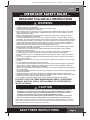
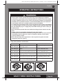
IMPORTANT SAFETY RULES
Read, Understand and Follow All Instructions Carefully Before Installing and Using this Product.
READ AND FOLLOW ALL INSTRUCTIONS
WARNING
•
To reduce the risk of injury, do not permit children to use this product. Always supervise
children and those with disabilities.
•
Children must stay away from this product and electrical cord(s).
•
Assembly and disassembly by adults only.
•
Risk of electric shock. Connect only to a grounding type receptacle, this product is provided
with a ground-fault circuit interrupter. If replacement of the plug or cord is needed, use only
identical replacement parts.
•
Always unplug this product from the electrical outlet before removing, cleaning, servicing or
making any adjustment to the product.
•Theunitisprovidedwithaground-faultcircuitinterrupter(GFCI).TotesttheGFCI,pushthe
test button. TheGFCIshouldinterruptpower.Push the reset button, power should be restored.
IftheGFCIfailstooperateinthismanner.TheGFCIisdefective.IftheGFCIinterruptspower
to the pump without the test button being pushed, a ground current is flowing, indicating the
possibility of an electric shock. Do not use this pump. Disconnect the pump and have the
problem corrected by a qualified service representative before using.
•
Do not bury the electrical cord. Locate the cord where it will not be damaged by lawn mowers,
hedge trimmers and other equipment.
•
To reduce the risk of electric shock, replace damaged cord immediately. Use a qualified
electrician to replace the cord.
•
To reduce the risk of electric shock, do not use extension cords, timers, plug adaptors or
converter plugs to connect unit to electric supply; provide a properly located outlet.
•
Do not attempt to plug in or unplug this product while standing in water or when your hands
are wet.
•
Donotuseanapplianceleakagecurrentinterrupter(ALCI)inplaceofaGFCIsincetheALCI
will not protect people.
•Positionthisproductawayfrompool,soastopreventchildrenfromclimbingonitandaccess
the pool.
•
Do not operate this product when pool is occupied.
•
To reduce the risk of entrapment hazard, never enter the pool if suction strainer component is
loose, broken, cracked, damaged or missing. Replace loose, broken, damaged, cracked or
missing suction strainer components immediately.
•Neverplayorswimnearsuctionfittings.Yourbodyorhairmaybetrappedcausingpermanent
injury or drowning.
•Topreventequipmentdamageandriskofinjury,alwaysturnpumpoffbeforechangingthefilter
control valve position.
•Neveroperatethisproductabovethemaximumworkingpressurestatedonthefiltertank.
•HazardousPressure.Impropertankvalvecoverassemblycouldcausethevalvecovertoblow
off and cause serious injury, property damage or death.
•Thisproductisintendedtobeusedonlyforthepurposesdescribedinthemanual!
FAILURE TO FOLLOW THESE WARNINGS MAY RESULT IN PROPERTY
DAMAGE, ELECTRIC SHOCK, ENTANGLEMENT OR OTHER SERIOUS
INJURY OR DEATH.
This product is for use with storable pools only. Do not use with permanently-installed pools. A
storable pool is constructed so that it is capable of being readily disassembled for storage and
reassembled to its original integrity. A permanently-installed pool is constructed in or on the
ground or in a building such that it cannot be readily disassembled for storage.
To reduce the risk of electric shock the pool must be installed no closer than 6 feet (1.8 m) from
any electrical outlet. Do not place portable appliances closer than 5 feet (1.5 m) from the pool.
These product warnings, instructions and safety rules provided with the product represent some common
risks of water recreation devices and do not cover all instances of risk and danger. Please use common
sense and good judgement when enjoying any water activity.
CAUTION

261
PO
(261PO) Sand Filter Pump & Saltwater System with E.C.O. ENGLISH 7.5” X 10.3” PANTONE 295U 07/23/2014
English
SAVE THESE INSTRUCTIONS
Page 4
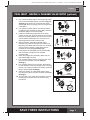
PARTS REFERENCE
Before assembling your product, please take a few minutes to check the contents
and become familiar with all the parts.
NOTE:
Drawingsforillustrationpurposeonly.Actualproductmayvary.Nottoscale.
1
5
9
10
11
21
2
13
14
20
19
3
6
7
4
12
15
16
17
18
8
22
23
24
25
26
40
18
49
42
46
48
47
45
28
29
30
31
32 33
34
*
28
29
30
35
36 37
*
39
27
44
43
28
29
30 31
*
32 33
41
28
29
30 35
*
36 38
*
If this pump was not purchased as part of a pool set, the above parts
can be ordered at www.intexcorp.com if needed.
Parts shown on this page are supplied with the pool package and are
shown here for assembly purposes only.

261
PO
(261PO) Sand Filter Pump & Saltwater System with E.C.O. ENGLISH 7.5” X 10.3” PANTONE 295U 07/23/2014
English
SAVE THESE INSTRUCTIONS
Page 5
" * ":
Optional.
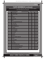
When ordering parts, be sure to quote the model number and part numbers.
PARTS REFERENCE (continued)
Before assembling your product, please take a few minutes to check the contents
and become familiar with all the parts.
REF. NO. DESCRIPTION QTY.
SPARE PART NO.
ECO20110 ECO15110
1 PRESSUREGAUGE 1 11224 11411
2 6-WAYVALVESET 1 11496 11378
3 DRAINOUTLETCOVER 1 11131 11131
4 TANKO-RING 1 11379 11379
5 SCREW 2 11381 11381
6 CLAMP 1 11380 11380
7 SANDSHIELD 1 11382 11382
8 CENTERPIPEHUB 1 11814 11813
9 DRAINVALVECAP 1 11456 11456
10 DRAINVALVEO-RING 1 11385 11385
11 LATERAL 10 11384 11384
12 HOSEWITHNUTS 2 11009 11009
13 SANDFILTERINTERCONNECTINGHOSE 1 11536 11390
14 LEAFTRAPNUT 1 11479 11479
15 LEAFTRAPO-RING 1 11232 11232
16 BASKET 1 11260 11260
17 FILTERHOUSINGNUT 1 11261 11261
18 L-SHAPEO-RING 4 11228 11228
19 SEDIMENTRELEASEVALVE 1 10460 10460
20 VALVEO-RING 1 10264 10264
21 FLOWSENSOR 1 11460 11460
22 ELECTROLYTICCELL 1 11372 11372
23 TITANIUMELECTRODE 1 11374 11389
24
E.C.O. ELECTRODE
1
11905 11900
25 PRE-FILTERASSEMBLY 1 11371 11371
26 PUMPMOTOR&CONTROL 1
11913EG 11911EG
27 L-SHAPEO-RING 1 11439 11439
28* PLUNGERVALVE(HOSEO-RING&STEPWASHERINCLUDED) 2 10747 10747
29* HOSEO-RING 2 10262 10262
30* STEPWASHER 2 10745 10745
31* STRAINERNUT 2 10256 10256
32* FLATSTRAINERRUBBERWASHER 2 10255 10255
33* THREADEDSTRAINERCONNECTOR 2 10744 11235
34* ADJUSTABLEPOOLINLETNOZZLE 1 11074 11074
35* ADAPTORB 2 10722 10722
36* STRAINERCONNECTOR 2 11070 11070
37* POOLINLETNOZZLE 1 11071 11071
38* STRAINERGRID 1 11072 11072
39
TEST STRIPS
1 19635 19635
40
LEAFTRAPCOVER 1 11480 11480
41
STRAINERGRID 1 10253
42
ELECTROLYTICCELLNUT 1 11432 11432
43 TITANIUMELECTRODEO-RING 1 11585 11585
44 CELLHOUSING 1 11915 11915
45
SANDFILTERPUMPMOTORINLETO-RING 2 11457 11457
46 ELECTRODECELLNUT
1
11582 11582
47
SANDFILTERPUMPANDCOMBOTANK 1 11803 11802
48
SANDFILTERPUMPTANKBASE 1 11801 11800
49
O-RINGONTITANIUMPLATES 1 11515 11515

261
PO
(261PO) Sand Filter Pump & Saltwater System with E.C.O. ENGLISH 7.5” X 10.3” PANTONE 295U 07/23/2014
English
SAVE THESE INSTRUCTIONS
Page 6
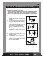
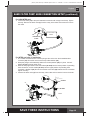
The strainer grid prevents large objects from jamming and/or damaging the filter pump. If
your pool has an inflatable top ring, install the strainer, nozzle and plunger valve before
inflating the pool liner top ring. The part numbers here onward refer to the parts depicted
in the Parts List section of this manual. To install, do the following:
1.
In a counter-clockwise motion unscrew plunger valve
union from the threaded strainer connector
(33)
(see
drawing 1).
Becarefulnottolosethesteprubber
washer
(30)
. Place the plunger valve on the ground in
a safe place.
2.
In a counter-clockwise motion unscrew the strainer nut
(31)
from the threaded connector
(33).
Leave the flat
washer
(32)
on the connector
(33)
.
3.
Install the strainer and plunger valve at the lower
position of pool outlet (marked "+").
Fromtheinsideof
the pool liner insert the connector
(33)
into one of the
pre-cut holes with the washer remaining on the
connector to be placed against the inside of the liner
wall.
4.
Beforeassembly,lubricatethethreadswithapetroleum
jelly. With the flat side of the strainer nut
(31)
facing
the outside wall of the liner in a clockwise motion screw
the strainer nut
(31)
back onto the threaded connector
(33) (see drawing 2)
.
5.
Fingertightenthestrainernut
(31)
onto the threaded
connector
(33)
.
6.
Grasptheplungervalveassembly.Makesurethestep
washer
(30)
is in place.
7.
In a clockwise motion screw the plunger valve union
back onto the threaded connector
(33) (see drawing 3)
.
8.
In a clockwise motion turn the plunger valve handle to
close position. Ensure the plunger valve is securely
closed. This will prevent water from flowing out during
filling of the pool
(see drawing 4)
.
POOL OUTLET - STRAINER & PLUNGER VALVE SETUP (optional)
1
2
3
1
2
32
33
INSIDE
LINER WALL
31
2
1
4
INSIDE
LINER WALL
30
Please visit
www.intexcorp.com
for the latest instructional video on the
installation and operation of this product.

261
PO
(261PO) Sand Filter Pump & Saltwater System with E.C.O. ENGLISH 7.5” X 10.3” PANTONE 295U 07/23/2014
English
SAVE THESE INSTRUCTIONS
Page 7
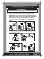
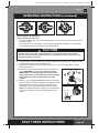
POOL INLET - NOZZLE & PLUNGER VALVE SETUP (optional)
1.
In a counter-clockwise motion unscrew plunger valve
union from the threaded strainer connector
(33)
(see
drawing 5).
Becarefulnottolosethesteprubber
washer
(30)
. Place the plunger valve on the ground in
a safe place.
2.
In a counter-clockwise motion unscrew the strainer
nut
(31)
from the threaded connector
(33).
Leave the
flat washer
(32)
on the connector
(33)
.
3.
Install the nozzle and plunger valve at the upper
position of pool inlet.
Fromtheinsideofthepoolliner
insert the connector
(33)
into one of the pre-cut holes
with the washer remaining on the connector to be
placed against the inside of the liner wall.
4.
Beforeassembly,lubricatethethreadswitha
petroleum jelly. With the flat side of the strainer nut
(31)
facing the outside wall of the liner in a clockwise
motion screw the strainer nut
(31)
back onto the
threaded connector
(33) (see drawing 6)
.
5.
Fingertightentheadjustablepoolinletnozzle
(34)
and the strainer nut
(31)
onto the threaded
connector
(33)
.
6.
Grasptheplungervalveassembly.Makesurethe
step washer
(30)
is in place.
7.
In a clockwise motion screw the plunger valve union
back onto the threaded connector
(33) (see
drawing 7)
.
8.
In a clockwise motion turn the plunger valve handle
to close position. Ensure the plunger valve is securely
closed. This will prevent water from flowing out during
filling of the pool
(see drawing 8)
.
9
. Adjust the direction of nozzle head pointing away
from the pool outlet for a better circulation result
(see
drawing 9)
.
10.
The pool liner is now ready to fill with water. Consult
the above-ground-pool owner’s manual for filling
instructions.
9
5
2
1
7
1
2
8
INSIDE
LINER WALL
6
32
33 34
INSIDE
LINER WALL
31
WATER
FLOW
POOL

261
PO
(261PO) Sand Filter Pump & Saltwater System with E.C.O. ENGLISH 7.5” X 10.3” PANTONE 295U 07/23/2014
English
SAVE THESE INSTRUCTIONS
Page 8
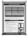
PRODUCT SPECIFICATIONS
SETUP INSTRUCTIONS
The sand filter removes suspended particles and sanitize your pool. Pool chemistry is a
specialized area and you should consult your local pool service specialist for details.
TOOLS REQUIRED: One (1) Phillips screwdriver
Pump location and mounting:
• Thesystemmustbeinstalledonasolidlevelandvibration-freebase.
• Providealocationprotectedfromtheweather,moisture,floodingandfreezingtemperature.
• Provideadequateaccess,spaceandlightingforroutine
maintenance.
• Pumpmotorrequiresfreecirculationofairforcooling.
Do not install the pump in a damp or non-ventilated location.
A team of 2 or more people is recommended for setting up this product.
Motor pre-filtering assembly setup:
1.
Remove the sand filter and its accessories from the packaging
carefullyandinspectforanyvisibledamage.Formissingor
damaged parts contact the appropriate Intex Service Center
listed in the separate “Authorized service Centers” sheet.
2.
In a counter-clockwise motion unscrew the leaf trap cover
(14)
from the pre-filter housing. Take out the basket
(16)
and
filter housing nut
(17) (see drawing 10)
.
3.
Connectthepre-filterhousingtothemotorwaterinlet.Note:
Align the connector in the pre-filter housing with the water inlet
on the motor
(see drawing 11)
.
10
14
17
16
40
Model: ECO20110 ECO15110
Power: 110-120VoltAC 110-120VoltAC
Amperage:
SaltwaterSystem-1.1A;FilterPump-6A
SaltwaterSystem-0.9A;FilterPump-3A
Wattage:
SaltwaterSystem-120W;FilterPump-650W
Ideal Salt Level: 3000 ppm (parts per million) 3000 ppm
Maximum Sanitizer Output/hour: 11 grams/hour 7 grams/hour
E.C.O. Cell Output Current: 800mA 500mA
Maximum working pressure:
2 bar (30 psi) 2 bar (30 psi)
Effective filtering area: 0.13 m
2
(1.44 ft
2
) 0.1 m
2
(1.1 ft
2
)
MaximumFlowRate:
8140 liters/hour (2150 gallons/hour)
6055 liters/hour (1600 gallons/hour)
Recommended filtering
media quantity:
No.20silicasand45Kg(100Lbs)
orglasssand32Kg(70Lbs).
No.20silicasand25Kg(55Lbs)
orglasssand18Kg(40Lbs).
Recommended filtering
media(Notincluded):
No.20silicasandorglasssand.Particlesizerange0.45to0.85
mm (0.018 to 0.033 inches). Uniformity Coefficient less than 1.75.
Limited Warranty: see “Limited Warranty”
HOW THE ELECTROCATALYTIC OXIDATION WORKS
The Electrocatalytic Oxidation (E.C.O.) is an Advanced Oxidation Processes (AOPs). When direct
current is applied to the electrocatalytic oxidation electrodes, water will be discharged to generate
“hydroxyl radicals”. The hydroxyl radical is a powerful oxidant, which oxidizes organic
contaminants,anddestroysbacteriaandalgae.Hydroxylradicalsincombinationwithfree
available chlorine provide the strongest and safest pool water sanitation.
11

261
PO
(261PO) Sand Filter Pump & Saltwater System with E.C.O. ENGLISH 7.5” X 10.3” PANTONE 295U 07/23/2014
English
SAVE THESE INSTRUCTIONS
Page 9
4.
In a clockwise motion screw filter housing nut
(17)
onto the motor water inlet
(See
drawings 12.1 & 12.2)
.
5.
Replace the basket
(16)
and leaf trap cover
(14)
back to the pre-filter housing
(See
drawings 13.1 & 13.2)
.
SETUP INSTRUCTIONS (continued)
Sand tank installation:
1.
Place the tank support base at the selected location.
2.
Place the tank on the tank support base
(See drawing 14.1).
3.
Connect the motor pre-filtering assembly unit to the tank support base
(See drawing 14.2)
.
NOTE: Ensure the pre-filter housing water inlet hose connection is facing towards the pool.
IMPORTANT: Some countries, especially in the European community, require the
product to be secured to the ground or to a base in a permanent upright position.
Check your local authorities to determine if there is a regulation in your area
regarding above-the-ground swimming pool filter-pumps. If yes, then the product can
be mounted to a platform using the two holes located in the base. See drawing 14.3.
The product can be mounted on a cement base or onto a wooden platform to prevent
accidental falling over.
• Themountingholesare6.4mmindiameterandspaced115mmapart.
• Usetwoboltsandlocknutswithamaximumof6.4mmindiameter.
12.2
12.1
17
17
13.213.1
16
14
40
14.1
115 mm
14.2
14.3

261
PO
(261PO) Sand Filter Pump & Saltwater System with E.C.O. ENGLISH 7.5” X 10.3” PANTONE 295U 07/23/2014
English
SAVE THESE INSTRUCTIONS
Page 10
SETUP INSTRUCTIONS (continued)
Sand loading:
IMPORTANT: Use No. 20 silica sand or glass sand with particle size range 0.45
to 0.85 mm (0.018 to 0.033 inches) and a Uniformity Coefficient less than 1.75.
NOTE: Before loading the tank with sand, ensure the center pipe hub assembly is
securely in place at the bottom of the tank, and vertically centered inside the tank.
1.
Place the sand shield
(7)
over the top of the center pipe. Pour the sand into the tank at a
slow rate.
(see drawing 15)
.
2.
Fillthetankapproximatelyhalfway,removethesandshield
(7)
.
(see drawing 16)
.
3.
Evenly distribute the sand inside the tank, then fill the tank with some water to provide a
cushioning effect when the remaining sand is poured in. This prevents the center pipe hub
(8)
from excessive shock
(see drawing 17)
. Place the sand shield
(7)
back and continue to pour
the sand into the tank.
4.
Sandshallbefilledbetweenthe“MAX”and“MIN”markedgaugeonthecenterpipe.Evenly
spread and level out the sand by hand
(see drawings 17 & 18)
.
5.
Remove the sand shield
(7)
.
6.
Wash away all sand around the top edge of the tank.
MAX
MIN
MAX
MIN
18
8
15
7
16
7
MAX
MIN
17
8

261
PO
(261PO) Sand Filter Pump & Saltwater System with E.C.O. ENGLISH 7.5” X 10.3” PANTONE 295U 07/23/2014
English
SAVE THESE INSTRUCTIONS
Page 11
6-way valve installation:
1.
Lower the 6-way valve over the tank slowly, and ensure the bypass pipe protruding
underneath the 6-way valve fits securely into the center pipe hub
(8)
top opening
(see
drawing 19)
.
IMPORTANT: There are three hose connection ports on the 6-way valve, ensure the
outlet connection (from filter to the pool) on the valve is facing towards the pool, and
the inlet connection (from motor to valve) is aligned with the motor outlet (see
drawing 20).
2.
Remove the clamp bolt, and install the clamp around the tank and 6-way valve flanges, then
replace the clamp bolt and use a phillips screwdriver (not included) to tighten it.
(see
drawing 21)
.
SETUP INSTRUCTIONS (continued)
WARNING
Improper tank valve and clamp assembly could cause the valve and clamp to blow off
and cause serious injury, property damage or death.
3.
Connect the sand filter interconnecting hose
(13)
between the 6-way valve inlet and motor
outlet,
and insert the electrolytic cell
(22)
intothe6-wayvalveoutlet.Handtightenthem
securely (
see drawings 22 and 23
).
4.
Screw and tighten the flow sensor
(21)
to the electrolytic cell
(22)
, then plug in the
electrolytic cell line cord and tighten the nut (
see drawings 24 and 25
).
6
19
21
8
20
WATER
INLET
WATER
OUTLET
22
23
24
25
21
22

261
PO
(261PO) Sand Filter Pump & Saltwater System with E.C.O. ENGLISH 7.5” X 10.3” PANTONE 295U 07/23/2014
English
SAVE THESE INSTRUCTIONS
Page 12
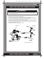
SAND FILTER PUMP HOSE CONNECTION SETUP
The 6-way valve has three hose connection ports.
1.
Connect one hose
(12)
end to the pre-filter inlet and the other end of the hose to the lower
plunger valve with the strainer. Ensure the hose nuts are securely tighten.
2.
Connect the second hose
(12)
between the electrolytic cell outlet and the upper plunger valve
with the inlet-nozzle. Ensure the hose nuts are securely tighten.
3.
The third hose connection port (drain/waste outlet) on the 6-way valve shall be directed to a
proper draining receptacle using a hose or pipe (not provided). Remove the drain cap before
attaching the drain/waste hose or pipe.
4.
The sand filter pump is now ready to filter the pool.
WARNING
• Positionthisproductawayfromthepool,soastopreventchildrenfromclimbing
on it and accessing the pool.
6-WAY VALVE
WATER LEVEL
ADJUSTABLE
POOL INLET
NOZZLE
THREADED
STRAINER
CONNECTOR
OUTSIDE
LINER WALL
PLUNGER
VALVE
(ILLUSTRATION NOT TO SCALE)
TO
DRAIN

261
PO
(261PO) Sand Filter Pump & Saltwater System with E.C.O. ENGLISH 7.5” X 10.3” PANTONE 295U 07/23/2014
English
SAVE THESE INSTRUCTIONS
Page 13
SAND FILTER PUMP HOSE CONNECTION SETUP (continued)
For INTEX pool size 16' and below:
1. In a counter-clockwise motion unscrew plunger valve union from the threaded strainer
connector
(33)
.Becarefulnottolosethesteprubberwasher
(30)
.
2. Grasptheplungervalveassembly.Makesurethestepwasher
(30)
is in place. Connect
adaptorB
(35)
to plunger valve union.
3. Remove wall plug and then insert the strainer
(36 & 38)
into the lower position of protruding
hose connection, and the nozzle
(36 & 37)
into the upper position of protruding hose
connection.AdaptorB
(35)
fits over the strainer connection
(36)
inserted into the connection.
Tighten securely.
4. Remove the drain valve
(3)
from the 6-way valve outlet and connect the hose to the outlet.
For NON-INTEX pool:
1.
Connect the hose
(12)
to the pool inlet/outlet connection with a large hose clamp. Tighten
securely. Remove the drain valve
(3)
from the 6-way valve outlet and connect the hose to
the outlet.
POOL
LARGE HOSE
CLAMP
12
3
POOL
36 & 37
3
36 & 38

261
PO
(261PO) Sand Filter Pump & Saltwater System with E.C.O. ENGLISH 7.5” X 10.3” PANTONE 295U 07/23/2014
English
SAVE THESE INSTRUCTIONS
Page 14
OPERATING INSTRUCTIONS
• Riskofelectricshock.Connectthisproductonlytoagroundingtypereceptacle
protected by a ground-fault circuit interrupter (GFCI) or residual current device (RCD).
Contact a qualified electrician if you cannot verify that the receptacle is protected by a
GFCI/RCD. Use a qualified electrician to install the GFCI/RCD, which has a maximum
rate of 30mA. Do not use a portable residual current device (PRCD).
•
To reduce the risk of electric shock, do not use extension cords, timers, plug adaptors
or converter plugs to connect unit to electric supply; provide a properly located outlet.
•
Do not attempt to plug in or unplug this product while standing in water or when your
hands are wet.
• Neveroperatethisproductabovethemaximumworkingpressurestatedonthefilter
tank.
• Alwaysswitchoffpumpbeforechangingthe6-wayvalveposition.
• Operatingthisproductwithoutwaterflowingthroughthesystemcancauseabuildup
of hazardous pressure which can result in an explosive situation, serious injury,
property damage or death.
• Nevertestthispumpwithcompressedair.Neveroperatethesystemwithwater
temperature above 35° C (95° F).
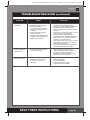
Valve Position Function Water Flow Direction
FILTER
(see drawing 26)
Normalfiltrationandregular
vacuuming of pool
Frompumpthroughfiltermedia
to pool
BACKWASH
(see drawing 27)
Reverses water flow to clean filter
media
Frompumpthroughfiltermedia
to valve waste/drain outlet
RINSE
(see drawing 28)
Forinitialstartupcleaningofthesand,and
leveling the sand bed after backwashing
Frompumpthroughfiltermedia
to valve waste/drain outlet
WASTE
(see drawing 29)
Forvacuumingdirectlytowaste,
lowering pool level or to drain the pool
Frompumptovalvewaste/drain
outlet bypassing the filter media
RECIRCULATE
(see drawing 30)
Forcirculatingwaterbacktopool
without going through the filter media
Frompumpthroughvalveto
pool bypassing the filter media
CLOSED
(see drawing 31)
Shuts off all flow to filter and pool
“Do not use this setting with pump running”
6-way valve positions and function:
WARNING
RETLIF
ESNIR
ETALUCRICER
ES
O
LC
ETSAW
ESN
IR
ETALUCRICER
HSAWKCAB
ESOLC
ETSAW
RETLIF
ESNIR
ETALUCRICER
HSAWKCAB
ETSAW
R
ETLIF
ESNIR
ER
HSAWKCAB
ESOLC
ETSAW
RETLIF
ESNIR
ETALUCRICER
HSAWKCAB
ESOLC
R
ETLIF
ETALUCRICER
HSAWKCAB
ESOLC
ETSAW
B
26
RETLIF
ESNI
R
ETALUCRICER
ES
O
LC
ETSAW
ESN
IR
ETALUCRICER
HSAWKCAB
ESOLC
ETSAW
RETLIF
ESNIR
ETALUCRICER
HSAWKCAB
ETSAW
R
ETLIF
ESNIR
ER
HSAWKCAB
ESOLC
ETSAW
RETLIF
ESNIR
ETALUCRICER
HSAWKCAB
ESOLC
R
ETLIF
ETALUCRICER
HSAWKCAB
ESOLC
ETSAW
B
27
RETLIF
ESNIR
ETALUCRICER
ES
O
LC
ETSAW
ESN
IR
ETALUCRICER
HSAWKCAB
ESOLC
ETSAW
RETLIF
ESNIR
ETALUCRICER
HSAWKCAB
ETSAW
R
ETLIF
ESNIR
ER
HSAWKCAB
ESOLC
ETSAW
RETLIF
ESNIR
ETALUCRICER
HSAWKCAB
ESOLC
R
ETLIF
ETALUCRICER
HSAWKCAB
ESOLC
ETSAW
B
28

261
PO
(261PO) Sand Filter Pump & Saltwater System with E.C.O. ENGLISH 7.5” X 10.3” PANTONE 295U 07/23/2014
English
SAVE THESE INSTRUCTIONS
Page 15
Initial startup and operation:
Before operating, be sure that:
• Allthehoseshavebeenconnectedandtightenedsecurely,andcorrectamountoffiltersand
have been loaded.
• Theentiresystemisconnectedtoagroundingtypereceptacleprotectedbyaground-fault
circuitinterrupter(GFCI)orresidualcurrentdevice(RCD).
OPERATING INSTRUCTIONS (continued)
CAUTION
The filter control valve has a closed position. The pump should never be on when
the valve is in the closed position. If the pump is operated with the valve closed, and
explosive situation could exist.
1.
Turn both plunger valve handles fully counter-clockwise until they stop. This opens the valves
to allow water to flow into the sand filter pump.
2.
Ensure the drain/waste outlet on the 6-way valve is not covered and directed to a proper
draining receptacle.
3.
Ensure the pump is off, depress the 6-way valve and turn it
to the “
BACKWASH
” position
(see drawings 27 & 32)
.
IMPORTANT: To prevent damage to the 6-way valve,
always depress the valve handle before turning. Always
switch off pump before changing the 6-way valve
position.
4.
Switch on the pump
(see drawing 33)
. Water is circulating
backward through the sand media and to waste/drain outlet.
Backwashuntilaclearflowofwaterisobservedinthe
waste/drain outlet or through the drain sediment window.
NOTE:
The initial backwash of the filter is recommended to
remove any impurities or fine sand particles in the sand
media.
32
1
2
33
OFF
ON
RETLIF
ESNI
R
ETALUCRICER
ES
O
LC
ETSAW
ESN
IR
ETALUCRICER
HSAWKCAB
ESOLC
ETSAW
RETLIF
ESNIR
ETALUCRICER
HSAWKCAB
ETSAW
R
ETLIF
ESNIR
ER
HSAWKCAB
ESOLC
ETSAW
RETLIF
ESNIR
ETALUCRICER
HSAWKCAB
ESOLC
R
ETLIF
ETALUCRICER
HSAWKCAB
ESOLC
ETSAW
B
29
RETLIF
ESNI
R
ETALUCRICER
ES
O
LC
ETSAW
ESN
IR
ETALUCRICER
HSAWKCAB
ESOLC
ETSAW
RETLIF
ESNIR
ETALUCRICER
HSAWKCAB
ETSAW
R
ETLIF
ESNIR
ER
HSAWKCAB
ESOLC
ETSAW
RETLIF
ESNIR
ETALUCRICER
HSAWKCAB
ESOLC
R
ETLIF
ETALUCRICER
HSAWKCAB
ESOLC
ETSAW
B
30
RETLIF
ESNI
R
ETALUCRICER
ES
O
LC
ETSAW
ESN
IR
ETALUCRICER
HSAWKCAB
ESOLC
ETSAW
RETLIF
ESNIR
ETALUCRICER
HSAWKCAB
ETSAW
R
ETLIF
ESNIR
ER
HSAWKCAB
ESOLC
ETSAW
RETLIF
ESNIR
ETALUCRICER
HSAWKCAB
ESOLC
R
ETLIF
ETALUCRICER
HSAWKCAB
ESOLC
ETSAW
B
31

261
PO
(261PO) Sand Filter Pump & Saltwater System with E.C.O. ENGLISH 7.5” X 10.3” PANTONE 295U 07/23/2014
English
SAVE THESE INSTRUCTIONS
Page 16
OPERATING INSTRUCTIONS (continued)
5.
Switchoffthepump,changethe6-wayvalveto“RINSE”position
(see drawing 28)
.
6.
Switch on the pump and run the pump for about one minute to level out the sand bed after
backwashing the sand media.
7.
Switchoffthepump,changethe6-wayvalveto“FILTER”position
(see drawing 26)
.
8.
Switch on the pump. The system is now operating in the normal filtering mode. Run the pump
until the desired pool water clearance is obtained and no more than 12 hours per day.
9.
Record the initial pressure gauge reading when the filter media is clean.
NOTE:
During initial setup of the system, it may be necessary to backwash frequently due to
unusual heavy dirt present in the water and sand. After that, as the filter removes dirt and
impurities from the pool water, the accumulated dirt in the sand media will cause the pressure
to rise and the flow to diminish. If there is no vacuuming device attached to the system and
the pressure gauge reading is in the yellow zone it is time to backwash the sand media, see
“BACKWASH”under“initialstartupandoperation”section.
Vacuumingdevice(i.e.Intexautopoolcleaner)attachedtothesystemmayalsocausethe
flow to diminish and the pressure to rise. Remove any vacuuming device from the system and
check if the pressure gauge reading has dropped from the yellow zone to the green zone.
Operation is subject to the following two conditions: (1) this device may not cause interference,
and (2) this device must accept any interference, including interference that may cause
undesired operation of the device.
Changes or modifications not expressly approved by the party responsible for compliance could
void the user’s authority to operate the equipment.
ThisequipmenthasbeentestedandfoundtocomplywiththelimitsforClassBdigitaldevice,
pursuanttopart15oftheFCCRules.Theselimitsaredesignedtoprovidereasonableprotection
against harmful interference in a residential installation. This equipment generates, uses and can
radiate radio frequency energy and, if not installed and used in accordance with the instructions,
maycauseharmfulinterferencetoradiocommunications.However,thereisnoguaranteethat
interference will not occur in a particular installation. If this equipment does cause harmful
interference to radio or television reception, which can be determined by turning the equipment
off and on, the user is encouraged to try to correct the interference by one or more of the
following measures:
•
Reorient or relocate the receiving antenna.
•
Increase the separation between the equipment and the receiver.
•
Connect the equipment into an outlet on a circuit different from that to which the receiver is
connected.
•
Consultthedealeroranexperiencedradio/TVtechnicianforhelp.

261
PO
(261PO) Sand Filter Pump & Saltwater System with E.C.O. ENGLISH 7.5” X 10.3” PANTONE 295U 07/23/2014
English
SAVE THESE INSTRUCTIONS
Page 17
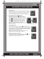
SALTWATER SYSTEM OPERATION
1. Start up the unit:
PlugthepowercordintotheelectricaloutletandtesttheGFCI/RCD
(circuitbreaker).Switchontheunit.WiththeFilterPumpturned“ON”
andoperating.Flashingcode“00”appearsontheelectroniccontrol
station’s LED, indicating that the unit is ready to be programmed.
2. Set operating hours for Saltwater System:
With code “00” flashing, press button to set the
desired operating hours. See the “Operating Time Table”
for the required operating hours related to each pool size.
Pressing will increase the time from 01 to 12 hours
maximum. If you have selected too many hours keep
pressing to repeat the cycle. The built-in timer will
now activate your Saltwater System, at the same time
each day, for the number of hours you have set.
NOTE:
The Saltwater System will not operate if the filter
pump is not operating.
3. Lock keypad controls:
With the desired hour value showing, press button until you hear a
“beep”.Thegreen“WORKING”indicatoronthecontrolpanelwilllightup
within a few seconds to indicate that the saltwater system has started
sanitizer production. Locking the control buttons into this setting prevents
unauthorized changing of the operating cycle.
NOTE:
If you forget to lock the keypad controls, the system will
automatically lock it and start working 1 minute later.
4.
Readjust operating time if necessary:
The operating hours can be re-adjusted if necessary. Press button
until you hear a “beep” to unlock the keypad and the current
programmed time will flash. Repeat steps 2 to 3.
(1 to 12 hours max per cycle)

261
PO
(261PO) Sand Filter Pump & Saltwater System with E.C.O. ENGLISH 7.5” X 10.3” PANTONE 295U 07/23/2014
English
SAVE THESE INSTRUCTIONS
Page 18
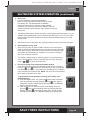
SALTWATER SYSTEM OPERATION (continued)
5
.
Boost cycle
•
Firsttimeinstallation,pressandhold“BOOST”
button for 5 seconds until the indicator lights up and the
LED display “80”. This indicates that the saltwater
system has started E.C.O. and more chlorine sanitizer
production.Youcanpressandholdthe“BOOST”buttonfor
another 5 seconds until the indicator is off, which will cancel the
Boostcycle.
•
The boost operating hours is 8 times the amount of time programmed into the system, i.e. if your
saltwater system operating time is 2 hours, the boost procedure will run 8 x 2 = 16 hours. After
boost procedure has been completed, the system will automatically switch to the normal
working mode.
•
Afteraheavyrainorifthepoolisdirty,pressthe“BOOST”buttontoshockthepoolagain.
6. Stand-by/power saving mode:
•
When the cycle ends, the green “SLEEP” indicator on the control panel
lightsupandtheLEDdisplayflashes“93”.ThesystemisnowinStand-By
mode. After a while, it shuts down and sets itself in a Power Saving mode.
The system will automatically turn itself back on in 24 hours, starting its
daily cycle of chlorine production.
•
The “SLEEP” indicator stays on, while the system is in the Power Saving
mode. The LED display however, goes blank after 5 minutes. Press any
button ( or ) to view the last LED code.
7. Running the pump alone without the Saltwater System:
To run the pump alone without the Saltwater System function, press and
hold both ( ) and ( ) buttons for 5 seconds until you hear a “beep” and
theLEDdisplayshows“FP”.Thepumpisnowoperatingalone.Tostopthe
pump,manuallyturntheswitchOFF.
NOTE:
The pump cannot be operated
alone under an automatic timer mode.
To bring back the initial automatic operating cycle setting of the
Saltwater System:
a) IftheLEDdisplayshows“FP”,pressthebuttonandtheoperating
hours set previously will begin flashing, press the button again or
simply wait 1 minute, and the LED will stay illuminated. The Saltwater
System cycle repeats again.
b) IftheunitisOFF,turntheswitchON,theLEDdisplayshows“FP”,
press the button and the operating hours set previously will begin
flashing, press the button again or simply wait 1 minute, and the
LED will stay illuminated. The Saltwater System cycle repeats again.

261
PO
(261PO) Sand Filter Pump & Saltwater System with E.C.O. ENGLISH 7.5” X 10.3” PANTONE 295U 07/23/2014
English
SAVE THESE INSTRUCTIONS
Page 19
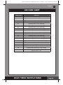
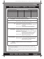
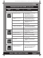
LED CODE CHART
LED Reading Definitions
FP FilterPumpWorkingMode
80 BoostMode
00 Stand-ByMode(Start-up)
01 MinimumOperatingHour(1hourremaining)
02 OperatingHours(2hoursremaining)
03 OperatingHours(3hoursremaining)
04 OperatingHours(4hoursremaining)
05 OperatingHours(5hoursremaining)
06 OperatingHours(6hoursremaining)
07 OperatingHours(7hoursremaining)
08 OperatingHours(8hoursremaining)
09 OperatingHours(9hoursremaining)
10 OperatingHours(10hoursremaining)
11 OperatingHours(11hoursremaining)
12 MaximumOperatingHours(12hoursremaining)
90 AlarmCode(LowPumpFlow/NoFlow)
91 Alarm Code (Low Salt Level)
92 AlarmCode(HighSaltLevel)
93 Stand-ByMode(OperatingProcessfinished)
“BLANK” NoPoweror“PowerSavingMode”waitingtostartnext
Saltwater System cycle.

261
PO
(261PO) Sand Filter Pump & Saltwater System with E.C.O. ENGLISH 7.5” X 10.3” PANTONE 295U 07/23/2014
English
SAVE THESE INSTRUCTIONS
Page 20
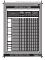
SALT & POOL WATER VOLUMES
• Whichkindofsalttouse:
Use only Sodium Chloride Salts
Useonlysodiumchloride(NaCl)saltthatisatleast99.8%pure.Itisalsoacceptabletouse
waterconditioningsaltpellets(thecompressedformsofevaporatedsalt).However,itwilltake
a longer time for them to dissolve.
Do not use iodized or yellow (yellow prussiate of soda)
colored salt.
Salt is added to the pool water and the electrolytic cell uses the salt to create the
sanitizer. So, the purer the salt the better the performance of the electrolytic cell.
• OptimumSaltLevels
The ideal salt level in the pool water is between 2500-3500 ppm (parts per million). The optimal
level is 3000 ppm.
A too low salt level will reduce the efficiency of the saltwater system and result in low sanitizer
production. A high salt level may generate a salty taste to the pool water (this may occur at a salt
level above 3500-4000ppm). Too high of a salt level may damage the power supply and cause
corrosion to pool metal fixtures and accessories. The Salt Table page of this manual, shows the
correct dosage of salt needed. The salt in the pool is constantly recycled. Salt loss occurs only
when pool water is physically removed from the pool. Salt is not lost due to evaporation.
• AddingSalt
1
. Switch on the unit, then press and hold both and button for 5 seconds, the LED
flashes“FP”.TheunitisnowinaFilterpumpworkingmodeandswitchthefilterpumponto
start the water circulation.
2
. KeeptheSaltwaterSystemturnedoff.
3
. Determine the amount of salt to be added (see “Salt Table”).
4
. Evenly spread the proper amount of salt around the inside perimeter of the pool.
5
. Avoid clogging the filter by not adding salt through the skimmer.
6
. Brushthepoolbottomtospeedupthedissolvingprocess.Donotallowsalttopileuponthe
bottom of the pool. Run the filter pump 24 consecutive hours to thoroughly dissolve the salt.
7
. After 24 hours and if all the salt is dissolved, turn on the Saltwater System, press button
until you hear a “beep”, code “00” flashing (see “System Operation” section steps 2 to 4) and
set the saltwater pool system to desired operating time (see “Operating Time Table”).
• RemovingSalt
If too much salt has been added, the unit will beep and display “Code 92” (see “Alarm Codes”).
Youwillneedtolowerthesaltconcentration.Theonlywaytodoso,istopartiallydrainthepool
andrefillitwithfreshwater.Drainandrefillapproximately20%ofthepool’swateruntilthe“Code
92” disappears.
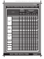
• PoolVolumeCalculation
Rectangular
Length x Width x Average Depth x 7.5 Length x Width x Average Depth
Circular
Length x Width x Average Depth x 5.9 Length x Width x Average Depth x 0.79
Oval
Length x Width x Average Depth x 6.0 Length x Width x Average Depth x 0.80
Types of Pool
Gallons
(pool size in feet)
Cubic Meters
(pool size in meters)
Page is loading ...
Page is loading ...
Page is loading ...
Page is loading ...
Page is loading ...
Page is loading ...
Page is loading ...
Page is loading ...
Page is loading ...
Page is loading ...
Page is loading ...
Page is loading ...
Page is loading ...
Page is loading ...
Page is loading ...
-
 1
1
-
 2
2
-
 3
3
-
 4
4
-
 5
5
-
 6
6
-
 7
7
-
 8
8
-
 9
9
-
 10
10
-
 11
11
-
 12
12
-
 13
13
-
 14
14
-
 15
15
-
 16
16
-
 17
17
-
 18
18
-
 19
19
-
 20
20
-
 21
21
-
 22
22
-
 23
23
-
 24
24
-
 25
25
-
 26
26
-
 27
27
-
 28
28
-
 29
29
-
 30
30
-
 31
31
-
 32
32
-
 33
33
-
 34
34
-
 35
35


Intex CS20110 Owner's manual
- Category
- Above ground pool accessories
- Type
- Owner's manual
Ask a question and I''ll find the answer in the document
Finding information in a document is now easier with AI
Related papers
Other documents
-
 Morton INVTMPCCLR32+INVTMPCCLN32+INVTMPCCNT2 Operating instructions
-
Bestway Chlorinator Owner's manual
-
 Intex Recreation GR-131SPF User manual
-
Blue Wave NE6161 User manual
-
Igenix IG8125 Datasheet
-
Steinbach SX1500 Krystal Clear Sand Filter Pump Owner's manual
-
Pool Technologie Justsalt Series User manual
-
-
 Pool Time 15145PTM Specification
-
Lovibond Single Method Strips Cl HR 10-200 - Chlorine HR User manual


