
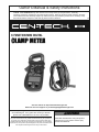
Owner’s Manual & Safety Instructions
Save This Manual Keep this manual for the safety warnings and precautions, assembly,
operating, inspection, maintenance and cleaning procedures. Write the product’s serial number in the back
of the manual near the assembly diagram (or month and year of purchase if product has no number). Keep
this manual and the receipt in a safe and dry place for future reference. 18e
When unpacking, make sure that the product is intact
and undamaged. If any parts are missing or broken,
please call 1-888-866-5797 as soon as possible.
Copyright
©
2007 by Harbor Freight Tools
®
. All rights reserved.
No portion of this manual or any artwork contained herein may be reproduced in
any shape or form without the express written consent of Harbor Freight Tools.
Diagrams within this manual may not be drawn proportionally. Due to continuing
improvements, actual product may differ slightly from the product described herein.
Tools required for assembly and service may not be included.
Read this material before using this product.
Failure to do so can result in serious injury.
SAVE THIS MANUAL.
Visit our website at: http://www.harborfreight.com
Email our technical support at: [email protected]
6 FUNCTION MINI DIGITAL

Page 2Item 96308
For technical questions, please call 1-888-866-5797.
SPECIFICATIONS
Functions
AC Current Measurement up to 400A
Resistance Measurement up to 200kΩ
Audible Continuity Test
Diode Test
AC/DC Measurement
Data Hold
Display
LCD maximum reading 1999
Over range Indicator
Low Battery Indicator
Maximum Capacity 1" Conductor
Test Leads 36" Long Red and Black with 90° Banana Plugs and 5/8" Nail Points
Accuracy
AC Volts: ± 1.5% of reading in 5 digits
DC Volts: ± 1.2% of reading in 5 digits
Meter Input Maximum 300 Volts AC or DC
Power Supply (3) 3-Volt Lithium Batteries CR-2032 (included)
Operating Temperature 32° - 104° F
Rating Cat II 300V Safety Rated

Page 3Item 96308
For technical questions, please call 1-888-866-5797.
SAFETY WARNINGS AND PRECAUTIONS
Read all safety warnings and all instructions.
Failure to follow the warnings and instructions may result in electric shock, fire and/or
serious injury.
Save all warnings and instructions for future reference.
1. Electrical shock can cause death or injury! NEVER TOUCH exposed conductors of
electricity.
2. Test cable voltages with care. One use one hand when securing the clamp around
cable.
3. Inspect the Meter before use. In addition to a general inspection, look specifically
for:
a. Pay special attention to the insulation protecting the connectors.
b. Check the leads for exposed metal, damaged insulation, and continuity.
c. Replace damaged test lead immediately, before use.
4. Do not use the Multimeter if:
a. Either of the test leads are damaged in any way.
b. Test leads are dirty or have residue on them.
c. The battery is low.
d. Near any explosive gases or fumes.
e. Any abnormal operation is detected.
(If in doubt about the condition of the Meter, have it serviced before use.)
f. The battery cover is open.
7. Power this Meter using only the battery(ies) referenced in the Specifications Chart.
8. Use caution when working near voltages above 30 VAC rms, 42 VAC peak, or
60 VDC. Voltages this high present a risk of electric shock.
9. Disconnect the circuit’s power before connecting the Meter in series, when
measuring current.
10. Connect the common (COM) test lead first and disconnect it last.
11. Hold the probes with fingers behind guards.
12. Avoid electrical shock. Use extreme caution when working near uninsulated
conductors or bus bars. Prevent body contact with grounded surfaces such as
pipes, radiators, ranges, and cabinet enclosures when testing voltages.
13. Observe work area conditions. Do not test voltages in damp or wet locations. Don’t
expose to rain. Keep work area clean and well lit.
14. Keep children away. Children must never be allowed in the work area.

Page 4Item 96308
For technical questions, please call 1-888-866-5797.
15. Stay alert. Watch what you are doing, use common sense. Do not operate any
Meter when you are tired.
16. Do not operate Meter if under the influence of alcohol or drugs. Read warning labels
on prescriptions to determine if your judgment or reflexes are impaired while taking
drugs. If there is any doubt, do not operate the Meter.
17. People with pacemakers should consult their physician(s) before use.
Electromagnetic fields in close proximity to heart pacemaker could cause pacemaker
interference or pacemaker failure.
18. Do not test voltage on circuits higher than 300 volts.
19. Do not test current on circuits higher than 400A.
20. Dress properly. Protective, electrically non-conductive clothes and nonskid footwear
are recommended when working.
21. Wear ANSI-approved safety goggles during use.
22. Only use accessories intended for use with this Meter.
23. Avoid damaging Meter. Use only as specified in this manual.
24. Prior to testing resistance, diodes, or continuity; disconnect all power to the circuit
and discharge all high-voltage capacitors.
25. Performance of this Meter may vary depending on battery condition.
26. Use the proper settings, terminals, techniques, and range for the tests performed.
Start with the range stated in the instructions.
27. Do not apply voltage to the Test Leads when the Meter is in the Ohms testing setting.
Damage can occur to the Meter.
28. Do not switch between testing modes with the Meter connected to a circuit.
29. Do not use the Meter at a setting marked as blank on the scale.
30. Have the Meter calibrated by a qualified technician every year to maintain accurate
results.
31. Do not disassemble Meter; take it to a qualified technician when service or repair is
required.
32. The warnings, cautions, and instructions discussed in this instruction manual cannot
cover all possible conditions and situations that may occur. It must be understood by
the operator that common sense and caution are factors which cannot be built into
this product, but must be supplied by the operator.
SAVE THESE INSTRUCTIONS.

Page 5Item 96308
For technical questions, please call 1-888-866-5797.
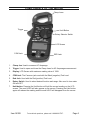
COMPONENTS OF THE METER
1.
Clamp Jaws
Trigger
LCD Screen
COM Jack
RED Jack
Rotary Selector Switch
Hold Button
Clamp Jaw. Used to measure AC Amperage.
2. Trigger. Used to open and close the Clamp Jaws for AC Amperage measurement.
3. Display. LCD Screen with maximum reading value of 1999.
4. COM Jack. The Common jack used with the Black (negative) Test Lead.
5. Red Jack. Used with the Red (positive) Test Lead.
6. Rotary Switch. Used to select desired function and range. Also used to turn meter
ON and OFF.
7. Hold button. Pressing the Hold button will hold the current reading on the LCD
screen. The word HOLD will also appear on the screen. Pressing the Hold button
again will release the reading and the word HOLD will disappear from the screen.

Page 6Item 96308
For technical questions, please call 1-888-866-5797.
OPERATION INSTRUCTIONS
Operating Procedures
NOTE: Follow these operating procedures whenever using this test meter for
personal safety and best results.
1. Before use, verify the meter’s operation by checking a known source.
2. Connect the (black) Common Test Lead before connecting the (red) Live Test Lead.
Remove in reverse order, disconnecting the Live Test Lead first, then the Common
Test Lead.
3. Remove all Test Leads from the Meter before using the Amp Clamp.
NOTE: This is a CAT II measurement tool. CAT II indicates low voltage, including
household voltage ranges. Do not exceed the voltage range of this meter, and do not use
for CAT III nor CAT IV applications.
Measuring DC Voltage
1. Insert the plug of the Black Test Lead into the COM jack. Insert the Red Test Lead
into the Red jack.
2. Set the Rotary Switch to the 300V position.
3. Connect the Red Test Lead to the hot source or load to be measured, and the Black
Test Lead to the neutral source to be measured.
4. Read the voltage value (VDC) on the LCD Screen. The screen will also display the
polarity of the Red Test Lead (“+” or “-”).

Page 7Item 96308
For technical questions, please call 1-888-866-5797.
Measuring AC Voltage
1. Insert the plug of the Black Test Lead into the COM jack. Insert the Red Test Lead
into the Red jack.
2. Set the Rotary Switch to the 300V~ position.
3. Connect the Red Test Lead to the hot source or load to be measured, and the Black
Test Lead to the neutral source to be measured.
4. Read the voltage value (V~) on the LCD Screen.
Measuring AC Current
1. Set the Rotary Switch to the desired AC current range.
2. Press the Trigger to open the Clamp Jaw. Clamp the Jaw on one of the wires to be
tested. Keep the wire in the center of the Jaw. NOTE: Only one wire can be tested at
a time, or else the readings from two wires will cancel each other and result in a false
reading.
3. CAUTION! Do not touch current bearing AC wires with your hand.
4. Read the reading on the display.

Page 8Item 96308
For technical questions, please call 1-888-866-5797.
Measuring Resistance
NOTE: Before measuring resistance, be sure the power to the circuit has been
disconnected and all capacitors have been discharged.
1. Insert the plug of the Black Test Lead into the COM jack. Insert the Red Test Lead
into the Red jack.
2. Set the Rotary Switch to the desired resistance range, either 2000 Ohms or 200
kOhms.
3. Connect the Red Test Lead to the hot source or load to be measured, and the Black
Test Lead to the neutral source to be measured.
4. Read the resistance value on the LCD Screen.
5. NOTE: The buzzer will sound if measured resistance is less than approximately 30
Ohms with the rotary switch in the 2000 Ohm position.

Page 9Item 96308
For technical questions, please call 1-888-866-5797.
Measuring for Continuity
1. Insert the plug of the Black Test Lead into the COM jack. Insert the Red Test Lead
into the Red jack.
2. Set the Rotary Switch to the continuity position.
3. Connect the Red Test Lead to the hot source or load to be measured, and the Black
Test Lead to the neutral source to be measured.
4. Read the resistance value on the LCD Screen. NOTE: The buzzer will sound if
measured resistance is less than approximately 30 Ohms.
Measuring a Diode
1. Insert the plug of the Black Test Lead into the COM jack. Insert the Red Test Lead
into the Red jack. NOTE: The polarity of the Red Test Lead is “+”.
2. Set the Rotary Switch to the diode position.
3. Connect the Red Test Lead to the anode of the diode, connect the Black Test Lead to
the cathode of the diode.
4. Read the approximate forward voltage on the LCD Screen. NOTE: The reading units
are “mV”.

Page 10Item 96308
For technical questions, please call 1-888-866-5797.
INSPECTION, MAINTENANCE, AND CLEANING
1. WARNING! Make sure the Rotary Selector Switch of the tool is in its “OFF”
position before performing any inspection, maintenance, or cleaning procedures.
2. BEFORE EACH USE, inspect the general condition of the tool. Check for loose
screws, misalignment or binding of moving parts, cracked or broken parts, damaged
electrical wiring, and any other condition that may affect its safe operation. If
abnormal noise or vibration occurs, have the problem corrected before further use.
Do not use damaged equipment.
NOTE: Replacement parts are not available for this product.
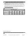
MAINTENANCE CHART
Maintenance Type
Before
Use
After
Use
Weekly Monthly
Every 6
Months
Yearly
Inspect tool for damage
(see #2, above)
X
Wipe off with clean, moist
cloth
X X X X X
Record Serial Number Here:
Note: If product has no serial number, record month and year of purchase instead.

Page 11Item 96308
For technical questions, please call 1-888-866-5797.
Replacing the Battery
1. When the Low Battery symbol is shown on the Display Screen, the batteries are
low and must be replaced.
2. Remove the screw on the Battery Compartment, and replace the batteries with (3)
new batteries of the same type (3VDC CR2032). Be sure all three batteries have the
“+” side facing upward. Incorrect battery polarity will prevent proper operation of the
meter. NOTE: You may have to move the clip to access the Battery Compartment.
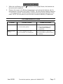
TROUBLESHOOTING
Problem Possible Causes Probable Solutions
Tool will not start 1. Batteries worn out.
2. Incorrect battery polarity
1. Replace batteries
2. Ensure that all batteries have
“+” facing upward in Battery
Compartment.
Erratic or incorrect
readings
1. Loose or damaged Test Leads.
2. Poor connection or corroded parts.
1. Check condition on Test Leads.
2. Check condition of part and clean if
necessary.

LIMITED 90 DAY WARRANTY
Harbor Freight Tools Co. makes every effort to assure that its products meet high
quality and durability standards, and warrants to the original purchaser that this product
is free from defects in materials and workmanship for the period of 90 days from the date
of purchase. This warranty does not apply to damage due directly or indirectly, to misuse,
abuse, negligence or accidents, repairs or alterations outside our facilities, criminal
activity, improper installation, normal wear and tear, or to lack of maintenance. We shall in
no event be liable for death, injuries to persons or property, or for incidental, contingent,
special or consequential damages arising from the use of our product. Some states
do not allow the exclusion or limitation of incidental or consequential damages, so the
above limitation of exclusion may not apply to you. THIS WARRANTY IS EXPRESSLY
IN LIEU OF ALL OTHER WARRANTIES, EXPRESS OR IMPLIED, INCLUDING THE
WARRANTIES OF MERCHANTABILITY AND FITNESS.
To take advantage of this warranty, the product or part must be returned to us
with transportation charges prepaid. Proof of purchase date and an explanation of the
complaint must accompany the merchandise. If our inspection verifies the defect, we
will either repair or replace the product at our election or we may elect to refund the
purchase price if we cannot readily and quickly provide you with a replacement. We will
return repaired products at our expense, but if we determine there is no defect, or that the
defect resulted from causes not within the scope of our warranty, then you must bear the
cost of returning the product.
This warranty gives you specific legal rights and you may also have other rights
which vary from state to state.
3491 Mission Oaks Blvd. • PO Box 6009 • Camarillo, CA 93011 • 1-888-866-5797
-
 1
1
-
 2
2
-
 3
3
-
 4
4
-
 5
5
-
 6
6
-
 7
7
-
 8
8
-
 9
9
-
 10
10
-
 11
11
-
 12
12


Ask a question and I''ll find the answer in the document
Finding information in a document is now easier with AI
Related papers
Other documents
-
 Pittsburgh Item 57397 Owner's manual
-
 Pittsburgh Item 57315 Owner's manual
-
Pittsburgh 63615 Owner's manual
-
Pittsburgh 62569 Owner's manual
-
Harbor Freight Tools Magnetic Digital Angle Gauge User manual
-
Ames 64013 Owner's manual
-
-
Ames 64020 Owner's manual
-
-

