
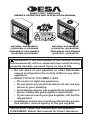
DIRECT-VENT FIREPLACE
OWNER’S OPERATION AND INSTALLATION MANUAL
NATURAL GAS MODELS
(V)CD36RN, (V)CD36RNE
PROPANE/LP GAS MODELS
(V)CD36RP, (V)CD36RPE
NATURAL GAS MODELS
(V)CD36TN, (V)CD36TNE,
PROPANE/LP GAS MODELS
(V)CD36TP, (V)CD36TPE
For more information, visit www.desatech.com
WARNING: If the information in this manual is not
— WHAT TO DO IF YOU SMELL GAS
• Do not touch any electrical switch; do not use any
-

www.desatech.com
116035-01J2
SAFETY
alteration, service or
maintenance can cause
-
for correct installation
-
additional information
-
-
stalled in an aftermarket,*
-
State of Massachusetts:
-
chemicals known to the State
of California to cause cancer or
-
-
This replace must be installed by a qualied
(certied or licensed) service person. It has
a sealed gas combustion chamber that uses
a coaxial pipe (pipe within a pipe and having
the same center) venting system. It brings in
fresh air for combustion through the outer pipe
and combustion gases are exhausted through
the inner pipe. If the glass door assembly and
venting pipe are not properly seated, con-
nected and sealed, carbon monoxide leakage
(spillage) can occur.
TABLE OF CONTENTS
Safety .................................................................. 2
Product Identication ........................................... 4
Local Codes......................................................... 4
Product Features ................................................. 5
Pre-Installation Preparation ................................. 5
Location of Termination Cap ................................ 9
Requirements for the Commonwealth of
Massachusetts............................................... 10
Venting Installation..............................................11
Fireplace Installation.......................................... 22
Operation ........................................................... 32
Inspecting Burners............................................. 37
Cleaning and Maintenance ................................ 38
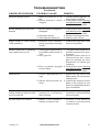
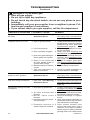
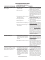
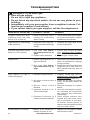
Troubleshooting ................................................. 39
Specications .................................................... 45
Replacement Parts ............................................ 45
Service Hints ..................................................... 45
Technical Service............................................... 45
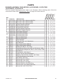
Parts .................................................................. 46
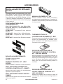
Accessories ....................................................... 52
Warranty ..............................................Back Cover

www.desatech.com
116035-01J 3
Early signs
of carbon monoxide poisoning resemble the
u, with headaches, dizziness or nausea. If
you have these signs, the replace may not
be working properly.
Have replace serviced. Some people are
more affected by carbon monoxide than oth-
ers. These include pregnant women, people
with heart or lung disease or anemia, those
under the inuence of alcohol and those at
high altitudes.
Propane/LP
and natural gas are odorless. An odor-making
agent is added to the gas. The odor helps you
detect a gas leak. However, the odor added to
the gas can fade. Gas may be present even
though no odor exists.
Make certain you read and understand all
warnings. Keep this manual for reference. It
is your guide to safe and proper operation of
this replace.
-
-
WARNING: Do not allow fans
SAFETY
Continued
-
-
adults away from hot surface to
-
-
dren when they are in the room
1. For propane/LP replace, do not place
propane/LP supply tank(s) inside any
structure. Locate propane/LP supply
tank(s) outdoors. To prevent performance
problems, do not use propane/LP fuel tank
of less than 100 lb. capacity.
2. If you smell gas
• shut off gas supply
• do not try to light any appliance
• do not touch any electrical switch; do not
use any phone in your building
• immediately call your gas supplier from
a neighbor’s phone. Follow the gas
supplier's instructions
• if you cannot reach you gas supplier, call
the re department.

www.desatech.com
116035-01J4
3. Never install the replace
• in a recreational vehicle
• in windy or drafty areas where curtains
or other combustible (ammable) objects
can make contact with the fireplace
front
• in high trafc areas
4. Turn fireplace off and let cool before
servicing, installing or repairing. Only a
qualied service person should install,
service or repair this replace. Have re-
place inspected annually by a qualied
service person.
5. You must keep control compartments,
burners and circulating air passages
clean. More frequent cleaning may be
needed due to excessive lint and dust
from carpeting, bedding material, etc.
Turn off the gas valve and pilot light before
cleaning replace.
6. Have venting system inspected annually by
a qualied service person. If needed, have
SAFETY
Continued
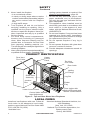
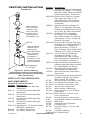
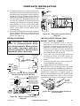
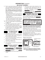
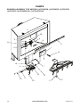
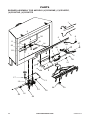
PRODUCT IDENTIFICATION
Figure 1 - Top and Rear Direct-Vent Fireplaces
Rear Vent
Flue Collar
Nailing
Flange
Top Vent
Flue Collar
Door Latch
Log Set
Ember
Tray
Junction
Box
Lower Louver Panel
Control Valve Variable
Input Adjustment
Piezo Ignitor with
Optional Remote and
Blower Control Mount
Upper
Louver
Panel
Glass Door
Assembly
LOCAL CODES
venting system cleaned or repaired. See
Cleaning and Maintenance, page 38.
7. Do not use any solid fuels (wood, coal,
paper, cardboard, etc.) in this replace.
Use only the gas type indicated on re-
place nameplate.
8. This appliance, when installed, must be
electrically grounded in accordance with
local codes or, in the absence of local
codes, with the National Electrical Code,
ANSI/NFPA 70.
9. Do not use replace if any part has been
exposed to or under water. Immediately
call a qualied service person to arrange
for replacement of the unit.
10. Do not operate replace if any log is
broken.
11. Do not operate replace with glass door
removed, cracked or broken.
12. Provide adequate clearances around air
openings.
Install and use replace with care. Follow all
local codes. In the absence to local codes,
use the current National Fuel Gas Code ANSI
Z223.1/NFPA 54* (USA).
*Available from:
American National Standards Institute, Inc.
1430 Broadway
New York, NY 10018
National Fire Protection Association, Inc.
Batterymarch Park
Quincy, MA 02269

www.desatech.com
116035-01J 5
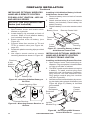
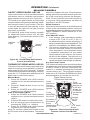
PRODUCT FEATURES
Figure 2 - Common Fireplace Locations
Flush with
a wall
Through exterior wall
enclosed in a chase
Corner
installation
• Your replace is designed to be used in
zero clearance installations. Wall or framing
material can be placed directly against any
exterior surface on the back, sides or top of
your replace, except where standoff spac-
ers are integrally attached. If standoff spac-
ers are attached to your replace, these
spacers can be placed directly against wall
or framing material. See framing details on
page 7.
• If you plan on installing a television or
entertainment center recessed above
your replace, it is recommended that you
maintain a minimum 18" above top of louver
opening.
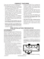
These are a few facts that can help you under-
stand and enjoy your direct-vent replace:
• The CD36R dedicated rear vent is best suited
for ush or corner installations when vented
horizontally through an exterior wall.
• The CD36T dedicated top vent is suited
for any application where height is nec-
essary to terminate the venting system
either through the roof (vertical) or to gain
sufcient height and offset to vent to an
outside/exterior wall (horizontal).
• The vent pipe installation is very important
to allow for proper operation. You must se-
lect the appropriate unit for your application
and follow the venting instructions to plan
your installation.
• This replace may be installed in any room
of your house provided all local codes and
these installation instructions are followed.
• Models (V)CD36R/T are equipped with a
millivolt gas control system that does not
require electricity to operate. A piezo ignitor
is provided to light the pilot without using
matches or lighters.
• Models (V)CD36RE/TE are equipped with
an electronic ignition system that requires
120VAC to operate. An electrode ignitor
automatically lights the pilot ame when
the replace is turned on.
• All models can accept an optional circulat-
ing air blower when 120 VAC connection
is supplied. If you plan to install an optional
blower, do not forget to wire the replace
outlet when framing.
• Each time you turn on your replace, you
may notice some amount of condensation
on the inside of the replace glass. This
is normal and will disappear after 10-20
minutes of operation.
• Your direct-vent gas fireplace system
(replace and venting) is a balanced and
sealed gas operating unit. It is highly
efcient because it uses outside air for
combustion while independently heating
the indoor air.
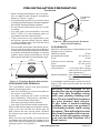
PRE-INSTALLATION PREPARATION
LOCATION AND SpACE
REqUIREMENTS
Determine the safest and most efcient loca-
tion for your DESA Heating, LLC direct-vent
replace. Make sure that rafters and wall
studs are not in the way of the venting system.
Choose a location where the heat output is
not affected by drafts, air conditioning ducts,
windows or doors. Figure 2 shows some com-
mon locations. Be aware of all restrictions and
precautions before deciding the exact location
for your replace and termination cap.
When deciding the location of your replace,
follow these rules:
• Do not connect this replace venting to a
chimney ue serving a separate solid-fuel
burning replace or appliance.
• Due to high temperatures, do not locate this
replace in high trafc areas, windy or drafty
areas or near furniture or draperies.
• Proper clearances must be maintained.
• If your replace is to be installed directly on
carpeting, vinyl tile or any combustible ma-
terial other than wood, it must be installed
on a metal or wood panel extending the full
width and depth of the replace. See Figure
3, page 6.

www.desatech.com
116035-01J6
• When locating termination cap, it is impor-
tant to observe the minimum clearances
shown in Figure 7, page 7.
• If recessing into a wall, you can avoid extra
framing by positioning your replace against
an already existing framing member.
• Do not recess termination cap into a wall
or siding.
• You may paint the termination cap with
450º F (232º C) heat-resistant paint to
coordinate with the exterior nish.
• There must not be any obstruction such
as bushes, garden sheds, fences, decks
or utility buildings within 24" from the front
of the termination cap.
• Do not locate termination cap where exces-
sive snow or ice build up may occur. Be sure
to clear vent termination area after snow falls
to prevent accidental blockage of venting
system. When using snow blowers, do not
direct snow towards vent termination area.
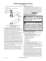
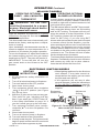
PRE-INSTALLATION PREPARATION
Continued
The (V)CD36R/T direct vent gas replace
heater is packaged with:
• one box containing a 4-log set located on
the burner in the rebox
• one bag containing the owner’s manual
with installation instructions, operator’s
guide, and warranty information
• one bag of glowing ember material
• one bag of vermiculite hearth treatments
Remove the shrink-wrap securing the 2 carton
trays to the unit. Lift the top carton tray off
and remove the four corner posts. Discard
the bottom tray once the unit is moved into
position.
Note: On rear vent models you must remove
the berboard collar protector located on the
rear collar before installing the replace and
venting system. See Figure 4.
Figure 4 - Removing Collar Protector
(Rear Vent Fireplace)
Fire Board
Collar
Protector
Figure 3 - Fireplace Bottom Dimensions
15"
(38.1 cm)
36"
(91.4 cm)
25"
(63.5 cm)
CLEARANCES
Minimum clearances to combustibles for the
replace are as follows:
*Back and sides 0"/cm
Perpendicular walls 12" (30.5 cm)
Floor 0"/cm
Ceiling to louver opening 40" (102 cm)
Front 36" (91.4 cm)
Top of Standoffs 0"/cm
Vent Surfaces 1" (26 mm) (See venting
instructions for specific
vent clearances.)
Mantel Clearances (See Mantel Clearances
for specifics on mantel
clearances.)
Combustible material with a maximum thick-
ness of 5/8" may be ush with the top front
of replace.
-
-

www.desatech.com
116035-01J 7
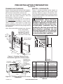
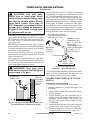
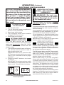
Figure 5 - Framing Clearances for
Installation Against an Exterior Wall
Figure 6 - Framing Clearances for Corner
Installation
PRE-INSTALLATION PREPARATION
Continued
FRAMING AND FINISHING
Figure 5 shows typical framing of this replace.
Figure 6 shows framing for corner installation.
All minimum clearances must be met.
For overall unit dimensions, framing allow-
ances and vent collar locations, see unit
dimensions in Figure 9, page 8.
For available accessories for this replace,
see Accessories on page 52. If you are us-
ing a separate combustible mantel piece,
refer to Figure 7 and Figure 8, page 8 for
proper height and clearances. You can install
noncombustible mantels at any height above
the replace.
Note: Noncombustible mantels may discolor!
14
3
/
4
"
(37.5 cm)
2"x4" Vertical
Double Stud
C
B
A
D
E
F
G
3
2
1
4
5
6
7
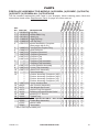
Ref. Mantel Depth Ref.
Mantel from
Top of Louver
Opening
1 16" (40.6 cm) A 14" (35.6 cm)
2 14" (35.6 cm) A 12" (30.5 cm)
3 12" (30.5 cm) B 10" (25.4 cm)
4 10" (25.4 cm) C 8" (20.3 cm)
5 8" (20.3 cm) D 6" (15.2 cm)
6 4" (10.1 cm) F 4" (10.1 cm)
7 2" (5.1 cm) G 2" (5.1 cm)
Figure 7 - Clearances for Combustible
Mantels
MANTEL CLEARANCES
Figure 7 shows projected mantel depths at
various heights above the top of the louver
opening. Figure 8, page 8, shows the mini-
mum allowable distances from various mantel
components in relation to the both sides of the
replace opening.
-
used and the face are sealed with
14
3
/
4
"
(37.5 cm)
THESE DIMENSIONS
ALLOW FOR 1" OF
CLEARANCE AT THE
SIDES AND BACK OF
THE FIREPLACE.
HOWEVER,
0" CLEARANCE IS
ALSO PERMITTED
AT ALL SIDES WHEN
FRAMED.
21" (53.3 cm)
TO CENTER OF
TOP VENT
14
3
/
4
"
(37.5 cm)
TO NAILING
FLANGES
56
3
/
4
"
(144 cm)
12
1
/
4
"
(31 cm)
TO
OPENING
28
5
/
8
"
(72.7 cm)
6
5
/
8
" ( 16.8 cm)
TO CENTER
OF REAR VENT
2
1
/
2
" (6.3 cm)
MIN. 1" (2.6 cm)
36
1
/
4
"
(92.1 cm)
12"
(30.5
cm)
2"x4" Flat Header
or Horizontal Cross
Member 12" Above
Top of Fireplace for
(V)CD36T Units Only
36"
(91.4 cm)

www.desatech.com
116035-01J8
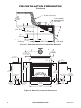
PRE-INSTALLATION PREPARATION
Continued
Figure 9 - Rear/Top Common Dimensions
Figure 8 - Side Clearances for Combustible Materials
8" (20.4 cm)
TO CENTER OF
8" TOP VENT
14
3
/
4
"
(37.5 cm)
TO NAILING
FLANGES
5/8"
(1.6 cm)
36"
(91.4 cm)
FACE DIM.
36
1
/
4
"
(92.1 cm)
FACE DIM.
15
3
/
8
"
(39 cm)
35
3
/
4
"
(90.8 cm)
2 "
(5 cm)
25"
(63.5 cm)
TO CENTER
OF 8"
REAR VENT
37" (94 cm)
TO NAILING
FLANGE
4
1
/
2
" (11.4 cm)
ELECTRICAL
INLET
8" (20.3 cm)
GAS SUPPLY
INLET
36
3
/
4
"
(93.4 cm)
36
1
/
4
"
(92.1 cm)
TO NAILING
FLANGE
2"
(5 cm)
2"
(5 cm)
38"
(96.5 cm)
4" (10.2 cm)
TO NAILING
FLANGE
WALL SWITCH
WIREWAY
WALL SWITCH
WIREWAY
2
1
/
2
"
(6.4 cm)
33°
SAFE
ZONE
1
1
/
2
"
(3.8 cm)
3
3
/
4
"
(9.5 cm)
6"
(15.2 cm)
5
1
/
2
"
(14 cm)
12"
(30.5 cm)
Perpendicular
Side Wall
Combustible
Material May
Be Used
Outer Surround
To Fireplace
Opening

www.desatech.com
116035-01J 9
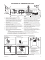
Figure 10 - Minimum Clearances for Termination Cap
LOCATION OF TERMINATION CAP
Fixed
Closed
Openable
Fixed
Closed
V
V
V
V
V
V
V
V
X
X
V
X
G
G
J
F
B
B
K
N
H
I
A
N
E
L
D
B
M
A
C
B
V
V
A
G
G
B
TERMINATION CAP
AIR SUPPLY INLET
GAS METER RESTRICTED AREA
(TERMINATION PROHIBITED)
A = clearance above grade, veranda, porch, deck, or
balcony [*12" (30.5 cm) minimum]
B = clearance to window or door that may be opened
[6" (15 cm) min. for 10,000 Btu or less; 9" (23 cm) in US
if between 10,000 and 50,000, 12" (30 cm) in Canada
if between 10,000 and 100,000; 12" (30 cm) in US if
greater than 50,000, 36" (91 cm) in Canada if greater
than 100,000]
C = clearance to permanently closed window
[minimum 12" (30.5 cm) recommended to prevent
condensation on window]
D = vertical clearance to ventilated soffit located above the
terminal within a horizontal distance of 24" (61 cm) from
the center-line of the terminal [18" (45.7 cm) minimum]
E = clearance to unventilated soffit [12" (30.5 cm) minimum]
F = clearance to outside corner (see below)
G = clearance to inside corner (see below)
H = *not to be installed above a meter/regulator assembly
within 36" (91.4 cm) horizontally from the center line
of the regulator
I = clearance to service regulator vent outlet [*72" (182.9 cm)
minimum]
J = clearance to non-mechanical air supply inlet to building
or the combustion air inlet to any other fireplace
[6" (15 cm) min. for 10,000 Btu or less; 9" (23 cm) in US
if between 10,000 and 50,000, 12" (30 cm) in Canada
if between 10,000 and 100,000; 12" (30 cm) in US if
greater than 50,000, 36" (91 cm) in Canada if greater
than 100,000]
K = clearance to a mechanical air supply inlet [*In Canada,
6 ft. (1.83m) minimum; In US 3 ft. (91 cm) above if within
10 ft. (3 m) horizontally]
L = † clearance above paved side-walk or a paved driveway
located on public property [*84" (213.3 cm) minimum]
M = clearance under veranda, porch, deck
[*12" (30.5 cm) minimum ‡]
N = clearance above a roof shall extend a minimum of
24" (61 cm) above the highest point when it passes
through the roof surface and any other obstruction within
a horizontal distance of 18" (45.7 cm)
† vent shall not terminate directly above a side-walk or paved driveway which is located between two
single family dwellings and serves both dwellings*
‡ only permitted if veranda, porch, deck or balconey is fully open on a minimum of 2 sides beneath the floor*
* as specified in CAN/CSA B149 (.1 or .2) Installation Codes (1991) for Canada and U.S.A.
Note: Local codes or regulations may require different clearances
A = 6" (15.2 cm)
Inside Corner
V
B
E
V
B = 6" (15.2 cm)
C = Maximum depth of 48" (121.9 cm)
for recessed location
D = Minimum width for back wall of
recessed location -
Combustible - 38" (965 mm)
Noncombustible - 24" (61 cm)
E = Clearance from corner in
recessed location-
Combustible - 6" (15.2 cm)
Noncombustible - 2" (5.1 cm)
Outside Corner Recessed Location
G
H
G = 12" (30.5 cm) minimum clearance
Balcony with No Side Wall
V
J
Combustible &
Noncombustible
H = 24" (61 cm)
J = 20" (50.8 cm)
Balcony with Perpendicular Side Wall
C
D
C
Termination Clearances for Buildings with Combustible and Noncombustible Exteriors
Openable

www.desatech.com
116035-01J10
REQUIREMENTS FOR THE COMMONWEALTH OF
MASSACHUSETTS
For all side wall horizontally vented gas fueled
equipment installed in every dwelling, building or
structure used in whole or in part for residential
purposes, including those owned or operated by
the Commonwealth and where the side wall ex-
haust vent termination is less than seven (7) feet
above nished grade in the area of the venting,
including but not limited to decks and porches,
the following requirements shall be satised:
MONOXIDE DETECTORS
At the time of installation of the side wall horizon-
tal vented gas fueled equipment, the installing
plumber or gastter shall observe that a hard
wired carbon monoxide detector with an alarm
and battery backup is installed on the oor level
where the gas equipment is to be installed. In
addition, the installing plumber or gastter shall
observe that a battery operated or hard wired car-
bon monoxide detector with an alarm is installed
on each additional level of the dwelling, building or
structure served by the side wall horizontal vented
gas fueled equipment. It shall be the responsibility
of the property owner to secure the services of
qualied licensed professionals for the installation
of hard wired carbon monoxide detectors.
In the event that the side wall horizontally
vented gas fueled equipment is installed
in a crawl space or an attic, the hard wired
carbon monoxide detector with alarm and
battery back-up may be installed on the next
adjacent oor level.
In the event that the requirements of this
subdivision can not be met at the time of
completion of installation, the owner shall
have a period of thirty (30) days to comply with
the above requirements; provided, however,
that during said thirty (30) day period, a battery
operated carbon monoxide detector with an
alarm shall be installed.
Each carbon monoxide detector as required
in accordance with the above provisions shall
comply with NFPA 720 and be ANSI/UL 2034
listed and IAS certied.
SIGNAGE
A metal or plastic identication plate shall be
permanently mounted to the exterior of the
building at a minimum height of eight (8) feet
above grade directly in line with the exhaust
vent terminal for the horizontally vented gas
fueled heating appliance or equipment. The
sign shall read, in print size no less than 1/2" in
size, "GAS VENT DIRECTLY BELOW. KEEP
CLEAR OF ALL OBSTRUCTIONS".
INSpECTION
The state or local gas inspector of the side
wall horizontally vented gas fueled equipment
shall not approve the installation unless, upon
inspection, the inspector observes carbon
monoxide detectors and signage installed in
accordance with the provisions of 248 CMR
5.08(2)(a) 1 through 4.
EXEMPTIONS: The following equipment is ex-
empt from 248 CMR 5.08(2)(a) 1 through 4:
• The equipment listed in Chapter 10 entitled
"Equipment Not Required To Be Vented"
in the most current edition of NFPA 54 as
adopted by the Board; and
• Product Approved side wall horizontally
vented gas fueled equipment installed in a
room or structure separate from the dwell-
ing, building or structure used in whole or
in part for residential purposes.
MANUFACTURER REqUIREMENTS
When the manufacturer of Product Approved
side wall horizontally vented gas equipment
provides a venting system design or venting
system components with the equipment, the
instructions provided by the manufacturer for
installation of the equipment and the venting
system shall include:
• Detailed instructions for the installation of
the venting system design or the venting
system components; and
• A complete parts list for the venting system
design or venting system.
provided
When the manufacturer of a Product Ap-
proved side wall horizontally vented gas fu-
eled equipment does not provide the parts for
venting the ue gases, but identies "special
venting systems", the following requirements
shall be satised by the manufacturer:
•
The referenced "special venting system" in-
structions shall be included with the appliance
or equipment installation instructions; and
• The "special venting systems" shall be Prod-
uct Approved by the Board, and the instruc-
tions for that system shall include a parts list
and detailed installation instructions.
A copy of all installation instructions for all
Product Approved side wall horizontally
vented gas fueled equipment, all venting in-
structions, all parts lists for venting instruc-
tions, and/or all venting design instructions
shall remain with the appliance or equipment
at the completion of the installation.

www.desatech.com
116035-01J 11
VENTING INSTALLATION
NOTICE: Failure to follow these in-
NOTICE: Do not seal termination
INSTALLATION pRECAUTIONS
• Wear gloves and safety glasses for pro-
tection
• Use extreme caution when using ladders
or when on roof tops
• Be aware of electrical wiring locations in
walls and ceilings
The following actions will void the warranty
on your venting system:
• Installation of any damaged venting com-
ponent
• Unauthorized modication of the venting sys-
tem (Do not cut or alter vent components)
• Installation of any component part not
manufactured or approved by DESA
• Installation other than as instructed by
these instructions
-
-
-
on the horizontal sections,
NOTICE: Read these instruc-
-
These models are tested and approved for
use with DESA Heating, LLC (direct-vent) pipe
components and terminations.
The venting system must terminate on the
outside of the structure and can not be at-
tached to a chimney or ue system serving a
separate solid fuel or gas burning appliance.
A direct-vent appliance must have its own
venting system. DO NOT common vent this
appliance.
These models are approved to be vented
either horizontally through an outside wall or
vertically through a roof or chase enclosure
using the following:
• When venting system terminates horizon-
tally on an outside wall, you may install
a standoff if the termination cap is to be
installed directly on a combustible nish
such as vinyl, wood, stucco, etc.
• Never run the vent downward as this may
cause excessive temperatures which could
cause a re.
• Vent pipe air space clearances to com-
bustibles are 1" on all sides except on the
horizontal sections, which requires 2" clear-
ance from the top of the pipe. Where the
termination cap penetrates a combustible
wall, 1" air space clearance is required.
• Have replace and selected vent compo-
nents on hand to help determine the exact
measurements when elbowing or offsetting.
Always use wall restops when penetrating
walls and restops when penetrating ceil-
ings or attic spaces.
• If using a venting conguration of only
horizontal venting with no vertical run, a
1/4" rise for every 12" of run toward the
termination is required.
WARNING: Read all instruc-
Failure to do so could result in
IMPORTANT: Do not seal vent cap to pipe.
Cap must be removable for servicing.

www.desatech.com
116035-01J12
INSTALLATION pLANNING
There are two basic types of direct-vent
installation:
• Horizontal Termination
• Vertical Termination
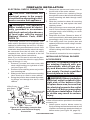
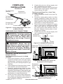
Horizontal Termination Installation
IMPORTANT: Horizontal square terminations
require only inner portion of wall restop. Hori-
zontal installations using round termination
require exterior portion of wall restop (see
Figure 20, page 15).
1. Set replace in its desired location and
determine route your horizontal venting
will take. Do not secure replace until all
venting has been installed. Some instal-
lations require sliding replace in and out
of position to make nal venting connec-
tions. Figures 18 through 25 on pages 14
through 17 show different congurations
for venting with horizontal termination that
will help you decide which application best
suits your installation. Check to see if wall
studs or roof rafters are in the path of your
desired venting route. If they are, you may
want to adjust location of replace.
2. Direct vent pipe sections and components
are designed with special twist-lock con-
nections.
Twist-Lock procedure: Female ends of
pipes have locking lugs (indentations).
These lugs will slide straight into match-
ing slots on male ends of adjacent pipes.
Push pipe sections together and twist
one section clockwise approximately one-
quarter turn until sections are fully locked
(see Figure 11).
Note: Horizontal runs of vent must be sup-
ported every three feet. Use wall straps
for this purpose.
3. Any straight pipe section, a 45° or 90°
elbow can be used when rst connecting
the venting system to replace. Elbows
are designed to twist-lock into any of four
90° positions to direct the venting system
to the desired location. IMPORTANT: Do
not attempt to alter the conguration of
elbow by cutting, twisting, bending, etc.
4. Assemble desired combination of pipe
and elbows to replace ue collar. If there
are long portions of venting run, preas-
sembled pipe sections may be installed
as subassemblies for convenience.
VENTING INSTALLATION
Continued
Figure 11 - Vent Pipe Connections
(Framing
Detail)
11
1
/
2
"
(29.2 cm)
11
1
/
2
" Inside Framing
(29.2 cm)
11
1
/
2
"
(29.2 cm)
8
1
/
2
"
(21.6 cm)
Vent
O
pening
Combustible Wall
Vent Opening
Noncombustible Wall
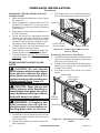
Figure 12 - Vent Opening Requirements
Center
of Hole
5. Carefully determine location where vent
pipe assembly will penetrate outside wall.
Center of hole should line up with center
line of horizontal vent pipe. Mark wall for a
11
1
/
2
" x 11
1
/
2
" square hole. Cut and frame
square hole in exterior wall where vent will
be terminated. If wall being penetrated is
constructed of noncombustible material,
such as masonry block or concrete, a
8
1
/
2
" hole with zero clearance is accept-
able (see Figure 12).
Female
Locking Lugs
Male
Slots

www.desatech.com
116035-01J 13
VENTING INSTALLATION
Continued
WARNING: Do not recess
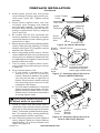
6. Position
horizontal vent cap in center of 8
1
/
2
" round
hole and attach to exterior wall with four
wood screws provided. Before attaching
vent cap to exterior wall, run a bead of
non-hardening mastic (pliable sealant)
around outside edges to make a seal
between it and outside wall.
Note: Four wood screws provided should
be replaced with appropriate fasteners for
stucco, brick, concrete or other types of
sidings (see Figure 13).
For vinyl
siding, stucco or wood exteriors, a siding
standoff may be installed between vent
cap and exterior wall. Siding standoff
prevents excessive heat from damaging
siding materials. Siding material must be
cut to accommodate standoff. Bolt vent
cap to standoff. Apply non-hardening
mastic around outside edge of standoff.
Position standoff/cap assembly in center
of the 11
1
/
2
" square hole and attach to
exterior wall with wood screws provided
(see Figure 14). Siding standoff must sit
ush against exterior fascia material.
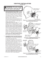
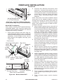
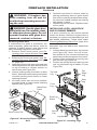
7.
Fit outer and inner wall restop
into wall before connecting horizontal run
to vent cap (see Figure 15).
Carefully move replace, with vent assem-
bly attached, toward wall and insert vent
pipe into horizontal termination. The pipe
overlap should be a minimum of 1
1
/
4
".
Slide wall restop against interior wall sur-
face and attach with screws provided (see
Figure 16, page 14). See Figure 17, page
14, for horizontal termination details.
Place replace into position and shim with
noncombustible material, if needed. Nail
or screw side anges to framing to secure
unit in place. IMPORTANT: Make sure re-
place is level before securing. If replace
is not level it will not work properly.
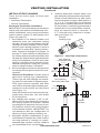
Figure 13 - Installing Horizontal Vent Cap
(Noncombustible Exterior)
Wood Screw
Vent Cap
Figure 14 - Installing Siding Standoff
(Combustible Exterior Wall)
Cut Siding Away
to Fit Standoff
Screws
Standoff
Vent
Cap
Apply Mastic to
All Four Sides
Figure 15 - Installing Outer Wall Firestop
(Combustible Exterior Wall)
Inner Wall
Firestop
Inner Wall
Firestop
Outer Wall
Firestop
Apply Mastic to
All Four Sides

www.desatech.com
116035-01J14
Figure 16 - Installing Inner Wall Firestop
VENTING INSTALLATION
Continued
Figure 17 - Typical Horizontal
Termination Cap Mounting with
Additional Siding Standoff Installed
Siding Standoff
Screws
High Wind
Termination
Apply
Mastic to
Outside
Edge of
Standoff
Exterior Wall with Vinyl Siding
11
1
/
2
" x 11
1
/
2
"
Framed Opening
Maintain 1"
Minimum Air
Space Around
Outer Pipe When
Penetrating a Wall
Minimum Pipe
Overlap 1
1
/
4
"
Wall
Firestop
Direct-Vent
Pipe
WARNING: Never run vent
downward as this may cause
-
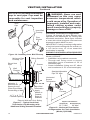
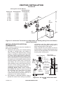
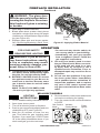
Figures 18 through 25 show different con-
gurations and alternatives for venting with
horizontal termination. Each gure includes
a chart with critical minimum and maximum
dimensions which MUST be met.
IMPORTANT: If using a venting conguration
of only horizontal venting with no vertical run,
a 1/4" rise for every 12" of run toward the
termination is required.
Recommended Applications for Rear Vent
Model (V)CD36R:
• Installation using cabinet surrounds
• Through wall using round or square
termination (up to a maximum of 18" of
horizontal pipe)
• Corner installation (Using one 45° elbow
and a maximum of 18" of horizontal pipe).
Figure 18 - Horizontal Termination
Congureation for Flush Installation
(Model (V)CD36R)
TO
H
Inner Wall
Firestop
Vent
Cap
Pipe
Section
Horizontal
Square
Termination
Wall
Firestop
Straight/Adjustable
Pipe 18" Max.
25
1
/
2
" Min. 22" Max
NOTICE: Do not seal termination

www.desatech.com
116035-01J 15
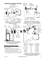
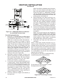
GROUND FLOOR INSTALLATION
Recommended Applications for Rear Vent
Model (V)CD36T:
• Installation using cabinet surrounds
• Through wall using round or square termi-
nation (up to 24" horizontal pipe)
• Corner installation (Using one 90° elbow
and a maximum of 24" of horizontal pipe)
VENTING INSTALLATION
Continued
Figure 20 - Horizontal Termination
Conguration Round Termination
(Model (V)CD36T)
Figure 19 - Horizontal Termination
Conguration for Corner Installation
(Model (V)CD36R)
Figure 21 - Horizontal Termination
Conguration For Corner Installation
Using One 90° Elbow (Model (V)CD36T)
Figure 22 - Horizontal Termination
Conguration with Vertical Rise and One
90° Elbow (Model (V)CD36T)
45
1
/
2
" None 26" Max.
57
1
/
4
" Min. 1 ft. 30" Max.
69
1
/
4
" Min. 2 ft. 74" Max.
81
1
/
2
" Min. 3 ft. 98" Max.
94" Min. 4 ft. 122" Max.
106" Min. 5 ft. 146" Max.
159" Min. 9 ft. 20' Max.
TO
H
H
V
Horizontal Square
Termination
Wall
Firestop
Straight/Adjustable
Pipe 18" Max.
Corner Installation
25
1
/
2
" Min. 24" Max
45°
Elbow
Wall
Firestop
Horizontal
Round
Termination
Exterior
Portion of Wall
Firestop (Round
Termination Only)
90°
Elbow
Wall
Firestop
Straight/
Adjustable
Pipe 24" Max.
Horizontal
Square
Termination
90°
Elbow
Corner Installation
45
1
/
2
" Min. 32
1
/
2
" Max
90° Elbow
Wall
Firestop
Square
Termination
Not to Exceed
(H) Limits
As
Required
for (V),
See Chart
for Pipe
Section
Required

www.desatech.com
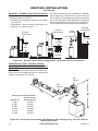
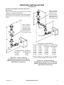
116035-01J16
Re co m me nd ed Ap pl ic at i on s Mo de ls
(V)CD36R and (V)CD36T:
• Installations requiring vertical rise on build-
ing exterior.
• Installation using snorkel termination to
achieve 1 ft. above grade.
VENTING INSTALLATION
Continued
Figure 23 - Snorkel Termination Conguration For Below Ground Installation
The following congurations show the mini-
mum vertical rise requirements for a horizontal
system using two 90° elbows.
Figure 24 - Horizontal Termination Conguration For Venting Using Two 90° Elbows
(Model (V)CD36T)
Horizontal (H
7' Min. 10' Max
8' Min. 12' Max
9' Min. 14' Max
10' Min. 16' Max
11' Min. 18' Max
13' Min. 20' Max
Snorkel terminations are available for installa-
tions requiring a vertical rise on the exterior of
the building. If installing snorkel below grade
you must provide proper drainage to prevent
water from entering snorkel (see Figure 23).
Do not back ll around snorkel termination.
90°
Elbow
90°
Elbow
Snorkel
Termination
12"
Min.
12" Min.
Adequate
Drainage
Snorkel
Termination
Snorkel
Termination
90° Elbow
12" Min.
Wall
Firestop

www.desatech.com
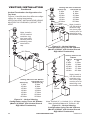
116035-01J 17
T
O
H
VENTING INSTALLATION
Continued
Figure 25 - Horizontal Termination Conguration for Venting Using Three 90° Elbows
(Model (V)CD36T)
TERMINATION
Note: Vertical restrictor must be installed in
all vertical installations.
1. Determine the route your vertical venting
will take. If ceiling joists, roof rafters or
other framing will obstruct the venting
system, consider an offset (see Figure 26)
to avoid cutting load bearing members.
Note: Pay special attention to these instal-
lation instructions for required clearances
(air space) to combustibles when passing
through ceilings, walls, roofs, enclosures,
attic rafters, etc. Do not pack air spaces
with insulation. Also note maximum verti-
cal rise of the venting system and any
maximum horizontal offset limitations.
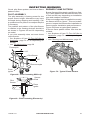
When installing
the OSR58-30 offset, it must be turned
20° off center line (see Figure 27, page
18). This will give you the 1" clearance
to horizontal framing members that are a
minimum of 12" above replace.
2. Set replace in desired location. Drop a
plumb line down from ceiling to position
Figure 26 - 45° and 30° Offset with Wall
Strap
Horizontal (H
5' Min. 2' Max. 6' Max
6' Min. 3' Max. 8' Max
7' Min. 4' Max. 10' Max
8' Min. 5' Max. 12' Max
12' Min. 8' Max. 20' Max
20' Min. 8' Max. 20' Max
90°
Elbow
90°
Elbow
90°
Elbow
Roof Flashing
Wall
Strap
45°
Elbows
WS-58
Wall Strap
2 - 2 x 4
Vertical
Header
OSR58-30
30° Offset
Return
Horizontal
Frame Member
of replace exit ue. Mark center point
where vent will penetrate ceiling. Drill a
small locating hole at this point.
Drop a plumb line from inside of roof to
locating hole in ceiling. Mark center point
where vent will penetrate roof. Drill a small
locating hole at this point.
1.5"
(38 mm)
12"
(305
mm)
1" (25 mm)

www.desatech.com
116035-01J18
1. Cut a 11
1
/
2
" square hole in ceiling using
locating hole as a center point. The open-
ing should be framed to 11
1
/
2
" x 11
1
/
2
"
(292 mm x 292 mm) inside dimensions,
as shown in Figure 12 on page 11 using
framing lumber the same size as ceiling
joists. If area above ceiling is an insulated
ceiling or an attic, nail restop from top
side. This prevents loose insulation from
falling into required clearance space. If
area above ceiling is a living space, in-
stall restop below framed hole. Firestop
should be installed with no less than three
nails per side (see Figure 28).
2. Assemble desired lengths of pipe and
elbows necessary to reach from replace
ue up through restop. Be sure all pipe
and elbow connections are fully twist-
locked (see Figure 11, page 12).
3. Cut a hole in the roof using locating hole as
a center point. (Cover any exposed open
vent pipes before cutting hole in roof.) The
11
1
/
2
" x 11
1
/
2
" hole must be measured on
the horizontal; actual length may be larger
depending on pitch of roof. There must
be a 1" clearance from the vent pipe to
combustible materials. Frame opening as
shown in Figure 12, page 12.
4. Connect a section of pipe and extend up
through hole.
VENTING INSTALLATION
Continued
Figure 28 - Installing Firestop
If area above is a living space, install
restop below framed hole.
If area above is an attic or insulated area,
install restop above framed hole.
Note: If an offset is needed to avoid obstruc-
tions, you must support vent pipe every 3
feet. Use wall straps for this purpose (see
Figure 26, page 17). Whenever possible,
use 45° elbows instead of 90° elbows. The
45° elbow offers less restriction to the ow
of ue gases and intake air.
5. Place ashing over pipe section(s) ex-
tending through roof. Secure base of
ashing to roof and framing with roong
nails. Be sure roong material overlaps
top edge of ashing as shown in Figure
26, page 17. There must be a 1" clearance
from vent pipe to combustible materials.
6. Continue to add pipe sections until height
of vent cap meets the minimum building
code requirements described in Figure 10
on page 9.
Note: You must increase vent height for
steep roof pitches. Nearby trees, adjoining
rooines, steep pitched roofs and other
similar factors may cause poor draft or
down-drafting in high winds. Increasing
vent height may solve this problem.
7. Twist-lock vent cap onto last section of
vent pipe.
Note: If vent pipe passes through any oc-
cupied areas abovethe rst oor, including
storage spaces and closets, you must enclose
pipe. You may frame and sheetrock enclosure
with standard construction material. Make
sure and meet minimum allowable clearances
to combustibles. Do not ll any required air
spaces with insulation.
Figure 27 - OSR58-30 Offset and Return
for (V)CD36T Series Units
C
L
3" Offset
1"
Offset
1" Clearance
1.5"
1"
1.5" Clearance
20°
3.5"

www.desatech.com
116035-01J 19
VENTING INSTALLATION
Continued
Figures 29 and 30 show two different congu-
rations for vertical termination.
VERTICAL VENT INSTALLATIONS USING
MULTIPLE 90° ELBOWS (V)CD36R REAR
VENT
Figure 29 - Vertical Venting
Conguration using One 90° Elbow
(Model (V)CD36R with Vertical Round
High Wind Termination)
Figure 30 - Vertical Venting
Conguration using Three 90° Elbows
(Model (V)CD36R with Vertical Round
High Wind Termination)
Horizontal
(H
Horizontal (H
8' Min. 2' Max. 12' Min. 8' Max
8' Min. 2' Max. 14' Min. 11' Max
8' Min. 2' Max. 16' Min. 14' Max
8' Min. 2' Max. 18' Min. 17' Max
8' Min. 2' Max. 20' Min. 20' Max
8' Min. 2' Max. 40' Max. 20' Max
Note: Vertical (V
1
) + Vertical (V
2
) = 40' Max.
Max. Horizontal Above 20' Vertical = 20'
8' Min. 2' Max
40' Max. 2' Max
90°
Elbow
90° Elbow
90°
Elbow
Note: Install a
VR-58 vertical
restrictor ring
into inner pipe
section prior to
attaching vent
termination cap.
Note: Install a
VR-58 vertical
restrictor ring
into inner pipe
section prior to
attaching vent
termination cap.

www.desatech.com
116035-01J20
VENTING INSTALLATION
Continued
Figures 31 and 34 show four different congu-
rations for vertical termination.
VERTICAL VENT INSTALLATIONS USING
MULTIPLE 90° ELBOWS (V)CD36T TOP
VENT
Figure 33 - Vertical Venting
Conguration Using Two 90° Elbows
(Model (V)CD36T with Vertical Round
High Wind Termination)
Note: Vertical (V
1
) + Vertical (V
2
) = 40' Max.
Max. Horizontal Above 14' Vertical = 20'
Figure 31 - Vertical Venting
Conguration using Three 90° Elbows
(Model (V)CD36T with Vertical Round
High Wind Termination)
Horizontal
8' Min. 9' Max
9' Min. 11' Max
10' Min. 13' Max
12' Min. 17' Max
14' Min. 20' Max
Horizontal (H
Horizontal (H
8' Min. 5' Max
10' Min. 8' Max
12' Min. 11' Max
14' Min. 14' Max
16' Min. 17' Max
18' Min. 20' Max
40' Max. 20' Max
8' Min. 6' Max
9' Min. 8' Max
10' Min. 10' Max
12' Min. 14' Max
14' Min. 18' Max
40' Max. 20' Max
Note: Install a
VR-58 vertical
restrictor ring
into inner pipe
section prior to
attaching vent
termination cap.
90° Elbow
90° Elbow
Note: Install a
VR-58 vertical
restrictor ring
into inner pipe
section prior to
attaching vent
termination cap.
90°
Elbow
Note: Install a
VR-58 vertical
restrictor ring
into inner pipe
section prior to
attaching vent
termination
cap.
Figure 32 - Vertical Venting
Conguration Using Two 90° Elbows
(Model (V)CD36T with Vertical Round
High Wind Termination)
Page is loading ...
Page is loading ...
Page is loading ...
Page is loading ...
Page is loading ...
Page is loading ...
Page is loading ...
Page is loading ...
Page is loading ...
Page is loading ...
Page is loading ...
Page is loading ...
Page is loading ...
Page is loading ...
Page is loading ...
Page is loading ...
Page is loading ...
Page is loading ...
Page is loading ...
Page is loading ...
Page is loading ...
Page is loading ...
Page is loading ...
Page is loading ...
Page is loading ...
Page is loading ...
Page is loading ...
Page is loading ...
Page is loading ...
Page is loading ...
Page is loading ...
Page is loading ...
Page is loading ...
Page is loading ...
Page is loading ...
Page is loading ...
-
 1
1
-
 2
2
-
 3
3
-
 4
4
-
 5
5
-
 6
6
-
 7
7
-
 8
8
-
 9
9
-
 10
10
-
 11
11
-
 12
12
-
 13
13
-
 14
14
-
 15
15
-
 16
16
-
 17
17
-
 18
18
-
 19
19
-
 20
20
-
 21
21
-
 22
22
-
 23
23
-
 24
24
-
 25
25
-
 26
26
-
 27
27
-
 28
28
-
 29
29
-
 30
30
-
 31
31
-
 32
32
-
 33
33
-
 34
34
-
 35
35
-
 36
36
-
 37
37
-
 38
38
-
 39
39
-
 40
40
-
 41
41
-
 42
42
-
 43
43
-
 44
44
-
 45
45
-
 46
46
-
 47
47
-
 48
48
-
 49
49
-
 50
50
-
 51
51
-
 52
52
-
 53
53
-
 54
54
-
 55
55
-
 56
56


