Page is loading ...

OPERAT
OR’S MANUAL
INCLUDING:ĂSERVICE KITS, GENERAL DESCRIPTION & TROUBLESHOOTING
BASIC PUMP
READ THIS MANUAL CAREFULL
Y BEFORE INST
ALLING,
OPERA
TING OR SER
VICING THIS EQUIPMENT
.
3” AIR MOTOR
50:1 RATIO
2 1/4” STROKE
ALSOINCLUDE MANUALS: 6641X-XAIR MOTOR MANUAL,FORM 3637-2 GENERAL INĆ
FORMATION SHEET.
66650
35
LB DRUM
66650
RELEASED:
6–23–95
(REV
. A) IPP/PSE
SERVICE KITS
• Use only genuine AROR replacement parts to assure compatible
pressure rating and longest service life.
• 637066-B for repair of Air Motor section.
• Order individual parts for repair of Lower Pump section.
GENERAL
DESCRIPTION
This model is designed for delivery of heavy viscosity fluids such as
chassis lubrication fluids. Material dispensing accessories and supply
lines and fittings must be capable of withstanding pressures developed
by pump.
• The ARO 50:1 ratio basic pump assembly consists of a 3" air motor
and lower pump end.
RATIO x REGULATED AIR PRESSURE TO AIR MOTOR = MAXIMUM FLUID
PRESSURE.
• The 50:1 ratio is an expression of the relationship between the air
motor area and the lower pump end area. When 150 p.s.i. (10 bar)
air pressure is supplied to the air motor, the lower pump end will
develop a maximum of 7,500 p.s.i. (517 bar) fluid pressure (at no
flow) - as the fluid control is opened, the flow rate will increase as
the air motor cycle rate increases to keep up with the demand.
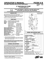
PUMP
DA
TA
Air
Motor
FIGURE 1
66410
1/2
NPT
Mat’l Outlet
Mat’l Inlet
Lower Pump
28.5"
20.2"
(723.9 mm)
(513.3 mm)
F031
OPERATING
AND SAFETY PRECAUTIONS
• HEED ALL WARNINGS.
• DO NOTEXCEED MAXIMUMWORKING PRESSURE OF7,500 PSI(517
BAR) AT 150 PSI (10 BAR) AIR INLET PRESSURE.
WARNING : HIGH PRESSURE DEVICE. Improper usage of
this equipment could result in serious injury. The possibility
of injection into the flesh is a potential hazard. Never allow any
part of the human body to come in front of or in direct contact
with the material outlet. An injection injury can be serious. If
injection should occur, contact a qualified physician immediĆ
ately for treatment.
• COMPONENTRUPTURE.This pumpiscapableof producinghighmaterial
pressure as stated on pump model plate.
• Be sure material hoses and other components are able to withstand fluid
pressures developed by this pump.
• Donot operatepump continuously at speedsin excess of75 cycles per minĆ
ute.
WARNING : PREVENT STATIC SPARKING. If static sparking
occurs, fire or explosion could result. Pump, dispensing
valve and containers must be grounded when handling inĆ
flammable fluids such as petroleum products, paints, lacĆ
quers, etc. and wherever discharge of static electricity is a
hazard.
• Usegrounded hoses (static wire) and be sure the object is grounded if it can
produce a static charge.
• Use grounded hoses (static wire) and be sure the object is
grounded if it can produce a static charge.
• Disconnectair line from pump air motor when system sits idle for long periĆ
ods of time.
THE
ARO CORPORA
TION
D
ONE ARO CENTER
D
BR
Y
AN, OHIO 43506–0151
E1995
THE ARO CORPORA
TION
D PRINTED IN U.S.A.
&
(419) 636–4242
D
F
AX (419) 636–21
15

66650
Page 2 of 4
AIR
AND LUBE REQUIREMENTS
WARNING HAZARDOUS PRESSURE. Do not exceed maxiĆ
mum inlet air pressure of 150 psi (10 bar). Operating pump at
higher pressure may cause pump damage and/or personal injuĆ
ry and/or property damage.
• Refer to general information sheet for additional safety precauĆ
tions and important information.
• Excessive air pressure will shorten the life of the pump.
• For maximum operating efficiency, the following air supply specifiĆ
cations should be maintained to this pump.
• AIR PRESSURE - Up to 150 P.S.I. (10 Bar)
• AIR FILTRATION - 50 micron
• LUBRICATED AIR SUPPLY
• AIR INLET SIZE - 1/4" NPTF
• Filtered and oiled air will allow the pump to operate more efficiently
and yield a longer life to operating parts and mechanisms.
• Lack of or an excessive amount of lubrication will affect the perforĆ
mance and life of this pump. Use the recommended lubricants.
• DAILY: Fill air line lubricator with a good grade of S.A.E. NO.
90 W non-detergent gear oil, adjust to 1 to 2 drops per minute.
• If pump is to be inoperative for more than a few hours at a time,
disconnect air supply and relieve all pressure from the system.
It is recommended that an oiler be installed in the airline as close as
possible to the pump. This increases the service life of the pump by
reducing wear of the air motor's internal parts.
INSTALLATION
FLUSH PUMP
1. Connect fluid hose to pump outlet and be sure all fittings are tight.
2. Turn air regulator knob counter-clockwise until it turns freely.
3. Pump has been tested in oil and a small amount remains for
protection against rusting. Immerse lower pump end in compatible
solvent.
4. Connect air hose coupler to connector on FRL.
5. Turn air regulator knob clockwise until air motor starts operating.
6. Flush pump with oil.
7. Disconnect air supply from air motor.
• CAUTION: Solvent used for flushing may not be compatible with
material being pumped. If this is the case, flush again with a comĆ
patible solvent.
• If pump is to be inoperative for an unspecified period of time, disĆ
connect air and relieve all pressure.
• If pump does not function properly, disconnect air and relieve all
pressure. Refer to Trouble Shooting.
OPERATING INSTRUCTIONS
1. Turn air regulator knob clockwise until air motor starts to cycle.
2. Allow pump to cycle slowly until it is primed and all air is purged
from the fluid hose or dispensing valve.
3. Turn off dispensing valve and allow pump to stall-check all fittings
for leakage.
4. Change air regulator setting until desired pressure and flow is obĆ
tained.
5. Inspect airline filter, open petcock to flush moisture or residue from
bowl.
6. Pump is recommended to operate between 30 PSI and 150 PSI
(not to exceed 75 cycles per minute.)
MAINTENANCE
The basic pump consists of two major components: 1. Air Motor, 2.
Lower Pump. The air motor is removable and is to be serviced sepaĆ
rately. Refer to air motor manual for service and parts.
• Periodically flush entire pump system with a solvent that is comĆ
patible with the material being pumped.
• Refer to disassembly procedures of air motor for correct breakĆ
down.
• Disassembly should be done on a clean work bench with clean
cloths to keep parts clean.
• If replacement parts are necessary, consult drawing containing
parts for identification.
• Before assembling, lubricate parts where required. When assemĆ
bling ``O" rings or parts adjacent to ``O" rings, care must be exerĆ
cised to prevent damage to ``O" rings and ``O" ring groove surfaces.
PUMP
DISASSEMBL
Y
NOTE: All threads are right hand.
CAUTION: DO NOT mar finish on (10) or (22) tube.
1. Clamp pump assembly in a vise on the air motor base assembly.
2. Place a strap wrench around (4) tube and loosen by turning counĆ
terclockwise. If the wrench slips on the (4) tube, wrap a piece of 400
sand paper around (4) tube and under strap wrench. (Note: Pipe
wrench will damage the finish of the tube.
3. After the (4) tube has been pulled down to expose the (2) rod, hold
air motor piston rod and unscrew the (2) rod from the air motor pisĆ
ton rod.
4. Remove the air motor assembly from the vise.
5. Vise the lower pump and remove (22) primer tube from (10) tube.
6. Remove (21) cotter pin, (20) primer, (19) seat, (18) washer, (17)
spacer, (16) body assembly (Disassemble body assembly if (14)
``u" cup or (15) spacer needs to be replaced.) and (12) washer from
assembly.
7. Remove (10) tube from (4) tube. Remove (5) gasket.
8. Pull rod assembly from (10) tube and disassemble (9) adapter from
(7) plunger to remove (8) ball.

Page 3 of 4
66650
FIGURE 2
1
2
3
4
5
6
7
8
9
10
11
12
13
14
15
16
17
18
19
20
21
22
23
FLUID
PASSAGE
24
F032
LOWER PUMP
PARTS LIST
ITEM Description Qty Part No.
1 Gasket 1 70834
2 Rod 1 79240
3 Nut 2 Y11-106-C
4 Tube 1 79239
5 Gasket 1 70837
6 Ball Stop 1 83276
7 Plunger 1 71127
8 Ball 1 Y16-209
9 Adapter 1 70817
10 Suction Tube 1 71126
11 Primer Rod 1 72394
12 Washer 1 71524
13 Snap Ring 1 Y147-68
14 ``U" Cup 1 Y186-4
15 Spacer 1 76705
16 Body 1 76704
17 Spacer 1 72392
18 Gasket 1 F21-65
19 Seat 1 6797
20 Primer 1 72387
21 Pin 1 Y15-21
22 Primer Tube 1 72389
23 Piston & Ball Check 1 71522
24 Piston & Tube 1 71523
PUMP
ASSEMBL
Y
1. Place (8) ball into (7) plunger and insert rod assembly into (10)
tube. Add (5) gasket to (10) tube and screw (4) tube onto (10) tube.
2. Place (12) spacer, (16) body assembly, (17) spacer, (18) washer,
(19) seat abd (20) primer into position. Secure by using (21) pin to
keep primer in place.
3. Screw (22) primer tube onto (10) suction tube.
4. Place air motor assembly in vise by clamping onto the machined
flats on the air motor base.
5. Install (1) gasket in throat of air motor base.
6. Thread rod assembly into piston rod of air motor.
-``Smart Parts" Keep these items on hand in addition to the Service Kits for fast repair and reduction of down time.

66650
Page 4 of 4
TROUBLE SHOOTING
No Material. (Stalled Pump.)
• Obstructed Material Line. Disconnect air supply. Relieve all fluid
pressure in pump. Remove Obstruction in system.
No Material (Pump Continually Cycles.)
• Empty material supply. Shut down system. Replenish material
supply.
Material on one stroke only. (Fast Upstroke.)
• Item (7) cup packing is worn. Remove the cup packing. Replace
cup packing.
Material on one stroke only. (Fast Downstroke.)
• Item (11) ball in (12) seat is not properly seating. Remove the seat.
Clean and inspect ball and seat. If either is damaged. replace with
new parts.
P/N 97999-643
/