Dynisco PT274 Series 4-20 mA User manual
- Category
- Measuring, testing & control
- Type
- User manual
This manual is also suitable for

From lab to production,
providing a window into the process
-1-
www.dynisco.com
Rev: 1217P/N: 974136 ECO: 30965
PT140/PT274 Series 4-20 mA Industrial
Hydraulic Pressure Transmiers
Operang Manual

From lab to production,
providing a window into the process
-2-
www.dynisco.com
Rev: 1217P/N: 974136 ECO: 30965
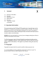
Table of Contents
Content Page Icon
General
Notes on safety
Technical data
Transport/delivery
Installaon
Commissioning
Maintenance
Troubleshoong
Declaraon of
Conformity
3
5
6
11
11
13
14
15
15

From lab to production,
providing a window into the process
-3-
www.dynisco.com
Rev: 1217P/N: 974136 ECO: 30965
1. General
1.1 Important informaon
1.2 Copyright
1.3 Explanaon of icons
1.4 Abbreviaons
1.5 Overview
1.6 Transmier Principle
of Operaon
1.1 Important information
This manual applies to the PT140 and PT274 products only. It must be kept near the
equipment in a readily and immediately accessible locaon at all mes. The content
of this manual must be read, understood and followed in its enrity. This applies in
parcular to the notes on safety. Following the safety instrucons will help to prevent
accidents, defects and malfuncons.
DYNISCO will not be held liable for any injury, loss or damage resulng from failure to
follow the instrucons in this manual.
If malfuncons occur in spite of having followed the operang instrucons, please
contact the DYNISCO customer service department (see the back of the man-
ual for contact informaon). This applies in parcular during the warranty
period.
1.2 Copyright
Copyright law requires that this manual be used for inhouse purposes only.
It is strictly forbidden to allow reproducon of any kind “in whole or in part” to
persons outside of Dynisco, without approval from Dynisco.

From lab to production,
providing a window into the process
-4-
www.dynisco.com
Rev: 1217P/N: 974136 ECO: 30965
1.3 Explanation of icons
The manual uses icons to indicate informaon pertaining to safety:
Risk of destrucon or damage to equipment, machines or installaons
General danger to life or limb
Specic danger to life or limb
You MUST do this
The safety instrucons are provided again in the individual chapters of the manual.
1.4 Abbreviations
The following abbreviaons are used:
OM Operang manual
PT pressure transmier
f.s. of full scale
BFSL Best Fit Straight Line
1.5 Overview
The Dynisco PT140 and PT274 are 4 - 20 mA pressure transmier. The pressure
sensing technology is bonded foil strain gage the same as other Dynisco products,
proven in such rugged applicaons such as automove hydraulic applicaons. The
rugged construcon is ideal for harsh industrial environments.

From lab to production,
providing a window into the process
-5-
www.dynisco.com
Rev: 1217P/N: 974136 ECO: 30965
1.6 Transmitter Principle of Operation
Through a diaphragm, the pressure transmier furnishes an electrical signal that is
proporonal to the pressure of the medium.
The pressure applied by the medium is forwarded to the measuring diaphragm. The
deecon of the measuring diaphragm changes the resistance of the strain gauge
bonded to the measuring diaphragm. The strain gage is a Wheatstone bridge.
The operator or owner of the larger overall system is responsible for
following the safety and accident prevenon regulaons that apply
to the specic applicaon.
The equipment is designed and manufactured to:
• Avoid physical injury or harm, which may be caused by direct or indirect
contact.
• Assure that the surface temperature of accessible parts or radiaon,
which would cause danger, is not produced.
• Eliminate non-electrical dangers, which are revealed by experience.
• Assure that foreseeable condions of overload shall not give rise to
dangerous situaons.
When planning machinery and using the PT, follow the safety and
accident prevenon regulaons that apply to your applicaon, e.g.:
• EN 60204, Electrical equipment in machines.
• EN 292, Machine safety, general design guidelines.
• DIN 57 100 Part 410, Protecon against electric shock.
2. Notes on safety

From lab to production,
providing a window into the process
-6-
www.dynisco.com
Rev: 1217P/N: 974136 ECO: 30965
Higher temperatures can result in damage and malfuncon. Do not install
the pressure transmier in places where this temperature is exceeded.
Mounng and electrical connecon of the PT must be done by specialists
with EMC training, following all applicable regulaons, and in
pressureless, voltage-free, intrinsically safe condion with the machine
switched o.
The machine must be secured against being switched back on!
3. Technical Data
3.1 Ordering Guide
3.2 Ordering Example
3.3 Process Connecons
3.4 Pressure Range - Full Scale
3.5 Opon Codes
3.6 Output
3.7 Zero & Span Adjustments
3.8 Performance Characteriscs
3.8.1 Combined Error (Accuracy)
3.8.2 Repeatability
3.8.3 Max. Pressure
(without Inuencing Operang Data)
3.8.4 Burst Pressure
3.8.5 Input Voltage
3.9 Temperature Inuence
3.10 EMC Requirements
3.11 Materials
3.12 Environmental Protecon
3.13 Dimensions

From lab to production,
providing a window into the process
-7-
www.dynisco.com
Rev: 1217P/N: 974136 ECO: 30965
3.1 Ordering guide
3.2 Ordering Example
3.3 Process Connections
3.4 Pressure Range - Full Scale
The exact meanings of the leer/digit combinaons are given in the corresponding
secons of chapter 3.
PT140: 1/8-27 NPT Internal
PT274: 1/4-18 NPT External
Other process connecons are available. Please consult factory for appropriate opon
code.
PTXXX-XX-XXX
psi Order Code
15 15 1000 1M
25 25 1500 1.5M
50 750 2000 2M
100 1C 3000 3M
250 2.5C 5000 5M
500 5C 7500 7.5M
750 7.5C 10000 10M

From lab to production,
providing a window into the process
-8-
www.dynisco.com
Rev: 1217P/N: 974136 ECO: 30965
Other ranges and pressure conguraons may be available, please consult factory.
3.5 Option Codes
PTXXX-XX-XXX
Please consult factory for list of approved opons.
3.6 Output
4 - 20 mA
3.7 Zero & Span Adjustments
PT140: No zero and span adjustments
PT274: Zero and span adjustments
3.8 Performance Characteristics
3.8.1 Combined Error (Accuracy)
Combined error is also known as accuracy which includes linearity, hysteresis and
repeatability, and is determined by BFSL (Best Fit Straight Line).
PT274: ±0.25% of full scale
PT140: ±0.5% of full scale
3.8.2 Repeatability
±0.1% of full scale

From lab to production,
providing a window into the process
-9-
www.dynisco.com
Rev: 1217P/N: 974136 ECO: 30965
3.8.3 Max. Pressure (Without Influencing Operating Data)
3.8.4 Burst Pressure
2 x full scale pressure
5x full scale pressure
3.8.5 Input Voltage
14 - 36 Vdc
3.9 Temperature Influence
ELECTRONICS HOUSING
Housing Temperature Range -29°C to +85°C (-20°F to +185°F)
Zero shi due to temperature change on electronics housing
2% f.s./100°F max.
Sensivity shi due to temperature change on the diaphragm.
2% f.s./100°F max.
3.10 EMC Requirements
Conforming to CE in accordance with EMC direcve.
Emied interference DIN EN 50081-1 (residenal area)
Immunity DIN EN 50082-2 (industrial area)
3.11 MATERIALS
Standard Diaphragm 15-5PH & 17-4PH Stainless Steel
3.12 Environmental Protection to IEC 529
IP54 Pressure Transmier without Connector
IP40 Pressure Transmier with 711600 Connector
IP65 Pressure Transmier with D06 opon
IP67 Pressure Transmier with D05 opon

From lab to production,
providing a window into the process
-10-
www.dynisco.com
Rev: 1217P/N: 974136 ECO: 30965
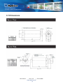
3.13 Dimensions

From lab to production,
providing a window into the process
-11-
www.dynisco.com
Rev: 1217P/N: 974136 ECO: 30965
4. Transport/Delivery
4.1 Transport/Packing/Transport Damage
4.2 Storage
4.3 Scope of Delivery
5. Installation
5.1 General Mounting Information
4.1 Transport/Packing/
Transport Damage
4.2 Storage
4.3 Scope of Delivery
• Do not let the PT be damaged by other items during transit.
• Use only the original packaging.
• Report transport damage to DYNISCO immediately in wring.
• Store the PT in original packaging only.
• Protect against dust and moisture.
• Pressure transmier
• Calibraon sheet
• Operang manual CD
5.1 General Mounng Informaon
5.2 Wiring
Insure the mounng hole is clear of any debris and is machined to the proper
dimensions.
Install unit into/onto the process connecon. (Do NOT torque transmier at this
me!) Allow me for the transmier temperature to equalize to the process tempera-
ture. This will help eliminate thread galling and ease removal later. There should be
NO pressure applied at this me.

From lab to production,
providing a window into the process
-12-
www.dynisco.com
Rev: 1217P/N: 974136 ECO: 30965
Insure the mounng hole is clear of any debris and is machined to the proper
dimensions.
Install unit into/onto the process connecon. (Do NOT torque transmier at this
me!) Allow me for the transmier temperature to equalize to the process tempera-
ture. This will help eliminate thread galling and ease removal later. There should be
NO pressure applied at this me.
Always use a torque wrench. Do not apply the tool to the housing or housing/sensor
connecon.
Aer temperatures have equalized ghten transmier into process connecon.
Before mounng the PT, check the process connecon carefully.
When removing the PT, carefully clean the process connecon of the transmier with
a so cloth while the medium is sll malleable (if measuring a solid).
Careful aenon should be paid in correctly machining the process connecon.
Failure to use the recommended mounng port may result in erroneous pressure
measurement, dicult transducer removal, premature sensor failure, process leaks,
and personnel hazard. In applicaons involving high temperature operaon and/or
repeated thermal cycling a good high quality an-seize compound should be applied
to the threaded surfaces.
5.2 Wiring
Bendix Connector PT02A-10-6P (or equivalent).
Pin 1: Excitaon +
Pin 2: Excitaon -
Pin 3: Not Used
Pin 4: Not Used
Pin 5: Calibraon
Pin 6: Calibraon

From lab to production,
providing a window into the process
-13-
www.dynisco.com
Rev: 1217P/N: 974136 ECO: 30965
6. Commissioning
6.1 Supply Voltage
6.2 Calibration and Zero
6.2.1 Zero and Span Adjustment - PT140 ONLY
6.1 Supply Voltage
6.2 Calibraon and Zero
6.3 Zero and Span Adjustment - PT140 Only
6.4 Zero and Span Adjustment - PT274 Only
Before pung the PT into operaon, make sure the PT is securely mounted and
sealed.
Using supply voltage which is dierent from that stated in the technical specicaons
can cause the transmier to malfuncon.
Dynisco recommends 24 Vdc. Supply voltages of 14 - 36 Vdc are permied.
All pressure transmiers have an internal calibraon signal. Connecng pins 5 and 6
switches the calibraon signal to the signal output. It is 80% of the full scale of the
transmier.
Calibrate in pressureless state and at room temperature. Other ambient temperatures
will corrupt the signal.
Do not change the installed posion of the PT aer calibraon. If the posion is
changed you must recalibrate.
The PT140 does not have zero and span adjustment....follow these steps to zero the
transmier.
1) Connect a meter or suitable display unit to the signal output.
2) Connect terminals 5 and 6. The calibraon signal is connected to the output.
3) Set the calibraon value (80% of nominal value) on the display unit.
4) Check the zero point seng on the display unit once again.
5) Readjust the zero point at operang temperature. Wait unl a steady operang
temperature is reached.
6) Set the zero point on the display unit.

From lab to production,
providing a window into the process
-14-
www.dynisco.com
Rev: 1217P/N: 974136 ECO: 30965
6.2.2 Zero and Span Adjustment - PT274 ONLY
The adjustment is made at two potenometer screws in the cover secon of the
electronic housing.
1) Remove the cap screws from the potenometers.
Zero pot is labelled as Z.
Span pot is labelled as S.
2) Connect a meter or suit
3) Adjust the zero pot adjusng screw “Z” and verify on the display.
4) Connect terminals 5 and 6. The calibraon signal is connected to the output.
5) Adjust the calibraon value (80% of nominal value) using the span pot adjusng
screw “S” and verify on the display unit.
6) Check the zero point seng on the display unit once again.
7) Readjust the zero point if required, as noted in step 3.
8) Readjust the zero point at operang temperature. Wait unl a steady operang
temperature is reached.
9) Set the zero point, if required.
7. Maintenance
7.2 Repair/Disposal
Installaon and Removal Instrucons
• PRIOR TO INITIAL INSTALLATION, VERIFY CORRECT MACHINING OF MOUNTING
HOLE.
• WHEN REINSTALLING, MAKE SURE MOUNTING HOLE IS CLEAR OF DEBRIS.
• ALWAYS REMOVE THE PT BEFORE CLEANING THE MACHINE WITH ABRASIVES OR
STEEL WIRE BRUSHES, ETC.
• DO NOT CLEAN THE “SCREWED-IN” SECTION OF THE PT WITH HARD OBJECTS – THIS
WILL DAMAGE THE PT.
• ELECTROSTATIC DISCHARGE MAY DAMAGE THE PT – TAKE ESD PRECAUTIONS.
Please send defecve PT units back to your DYNISCO representave.
For DYNISCO addresses, see the back cover of the operang manual.

From lab to production,
providing a window into the process
-15-
www.dynisco.com
Rev: 1217P/N: 974136 ECO: 30965
7.3 Warranty
8. Troubleshooting
9. CE Declaration of Conformity
Dynisco Pressure transmiers will provide excellent service and superior performance
if proper care is taken during handling, installaon, and use. This DYNISCO product
is warranted under terms and condions set forth in the DYNISCO web pages. Go to
www.dynisco.com and click “warranty” at the boom of any page for complete
details.
Symptom Correcve Acons
Output Not at Zero 1) Preform Zero Adjustment
Output is Negave at Zero Pressure 1) Process temperature has cooled down since
last Set Zero. Wait for process to fully heat up
to operang temperature.
No response to changes in 1) Check Port/Piping for blockage
applied pressure
Erroneous Pressure Reading 1) Was transmier zeroed at process operang
temperature with no pressure applied
Strong zero shi when 1) Mounng hole incorrectly produced
(alignment error)
2) Mounng torque too high...adjust to max
22NM.
screwing in
On-File at Dynisco

From lab to production,
providing a window into the process
-16-
www.dynisco.com
Rev: 1217P/N: 974136 ECO: 30965
DyniscoLLC
38 Forge Parkway
Franklin, MA 02038
USA
Tel: +1 508 541 9400
Fax: +1 508 541 9436
Email: Inf[email protected]
Dynisco Extrusion
1291 19th St Ln NW
Hickory, NC 28601
Tel: 828-326-9888
Fax: 828-326-8882
Email: Inf[email protected]
Dynisco Polymer Test
Westgate II
730 Hemlock Road
Morgantown, PA 19543
Sales & Service:
Tel: 508-541-9400
Fax: 508-541-6206
Email: Inf[email protected]
Dynisco Europe GmbH
Wannenäckerstraße 24
74078 Heilbronn
Deutschland
Tel: +49 7131 2970
Fax:+49 7131 23260
Email: DyniscoEurope@dynisco.com
Dynisco Instruments S.a.r.l.
466, rue du Marché Rollay
94500 Champigny sur Marne
France
Tel: +33 1 4881 8459
Fax: +33 1 4881 8334
Email: DyniscoFr[email protected]
Dynisco.s.r.l.
Via Adriaco, 2/2
20162 Milano
Italia
Tel: +39 02 661 01733
Fax: +39 02 661 02908
Email: DyniscoItaly@dynisco.com
Dynisco UK Ltd.
Silver Birches Business Park
Aston Road, Bromsgrove
Worcestershire B60 3EU
Great Britain
Tel: +44 1527 577077
Fax: +44 1527 577070
Email: [email protected]
Dynisco SPOL, S.R.O.
cp. 579
756 55 Dolni Becva
Czech Republic
Tel: +42 0571 647228
Fax: +42 0571 647224
Email: Dynisco_cz@ova.pvtnet.cz
Dynisco B.V.
Muziekplein 67
PO Box 666
NL-5400 AR Uden
The Netherlands
Tel: +31 413 250665
Fax: +31 413 260548
Email: Dynisco-BV@dynisco.com
-
 1
1
-
 2
2
-
 3
3
-
 4
4
-
 5
5
-
 6
6
-
 7
7
-
 8
8
-
 9
9
-
 10
10
-
 11
11
-
 12
12
-
 13
13
-
 14
14
-
 15
15
-
 16
16


Dynisco PT274 Series 4-20 mA User manual
- Category
- Measuring, testing & control
- Type
- User manual
- This manual is also suitable for
Ask a question and I''ll find the answer in the document
Finding information in a document is now easier with AI
Related papers
Other documents
-
Omega DP400S Owner's manual
-
-
Telex DSP-223 User manual
-
 Hunter Fan 30716 User manual
-
Vulcan-Hart ES25-ML-52642 User manual
-
 Land Pride RCD1884 User manual
-
Rosemount PB Series Owner's manual
-
 Valmet SMART-PULP Operating instructions
-
Rosemount 3201 Hydrostatic Interface Unit Modbus™ Protocol Owner's manual
-
Dwyer Series 7000 Spirahelic® User manual


