Page is loading ...

DOBLE SOBRE EL CANTO DE LA PUERTA
FOLD OVER THE DOOR RIM
Póliza de garantía. Este producto está
garantizado por URREA
HERRAMIENTAS PROFESIONALES,
S.A. DE C.V., km 11,5 Carr. A El Castillo,
45680 El Salto, Jalisco. UHP900402Q29,
Teléfono 01 33 3208-7900 contra
defectos de fabricación y mano de obra
con su reposición o reparación sin
cargo por el período de 25 años. Para
hacer efectiva esta garantía, deberá
presentar el producto acompañado de
su comprobante de compra en el lugar
de adquisición del producto o en el
domicilio de nuestra planta mismo que
se menciona en el primer párrafo de
esta garantía. En caso de que el
producto requiera de partes o
refacciones acuda a nuestros
distribuidores autorizados. Los gastos
que se deriven para el cumplimiento de
esta garantía serán cubiertos por Urrea
Herramientas Profesionales, S.A. de
C.V. Esta garantía no será efectiva en
los siguientes casos:
a).- Cuando el producto haya sido
utilizado en condiciones distintas a las
normales.
b).- Cuando el producto hubiera sido
alterado de su composición original o
reparado por personas no autorizadas
por el fabricante o importador
respectivo.
This product has a 25 years warranty by Urrea
Herramientas Profesionales S.A. de C.V.
against any manufacturing defect, with its
repair or replacement during its life expectancy.
The warranty is not applicable if the product
does not show the LOCK brand, if the product
is worn out by its daily use, shows signs of
abuse, damage, its original composition has
been altered, or specifies a different warranty.
In order to make the warranty effective, the
product must be taken to the company or to
the place of purchase along with its receipt.
PLANTILLA
TEMPLATE
INSTRUCTIVO, INSTALACIÓN Y PLANTILLA PARA MANIJA TUBULAR
TUBULAR LEVER INSTALATION INSTRUCTIONS AND TEMPLETE
Frente de la Puerta
Door Front
Canto de la Puerta
Door Rim
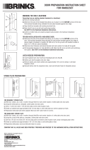
PREPARACIÓN DE LA PUERTA
DOOR PREPARATIONS
1
2
3
Usar la plantilla donde estan dibujados los agujeros para marcar las distancias y centros a perforar.
Marcar el centro del canto de la puerta y decidir la distancia a la cerradura princial
(se recomienda 127 mm entre las dos cerraduras (combos).
Dibujar el círculo para la perforacíon del cerrojo en el canto de la puerta 24 mm (15/16") de diámetro.
Dibujar en el canto de la puerta el área donde irá la placa de la cerradura.
Use the template, in which the holes are drawn, to mark distances and centers to drill.
Mark the rim center of the door and decide the distance to the main lock. It’s recommended 127 mm between both locks (combo set)
Draw the circle for the drill of the deadbolt in the rim of the door, it’s recommended 24 mm (15/16”) of diameter.
In the rim of the door, draw the area in which the plate of the lockset will go.
Marcar el centro del agujero donde se montará el cerrojo
(se debe seleccionar la distancia al canto de la puerta entre las dos medidas fijas posibles, 60 ó 70 mm).
Dibujar el círculo para la perforación donde se instalará el cerrojo con un diámetro exterior de 54 mm. (2 1/8")
Mark the center of the hole where the deadbolt will be mounted. (The distance to the rim of the door must be select between two possible sizes, 60 or 70 mm)
Draw the circle of the drill where the deadbolt will be set up with an outer diameter of 54 mm (2-1/8”).
Perfore cuidadosamente la puerta utilizando un taladro con sierra rotativa según las medidas anterioremente citádas y haciendo
primero el agujero mayor y luego el del canto de la puerta.
Ranurar a 3 mm de profundidad con un formón la caja donde va la placa del cerrojo.
Drill carefully according to the previously mentioned sizes, making first the bigger hole and then the rim of the door.
With a wood chisel, groove 3 mm depth where the strike of the deadbolt will fall.
Agujero
pasado 2-1/8”
de diámetro
(54 mm)
Agujero
15/16” de
diámetro
(24 mm)
NOTAS IMPORTANTES:
Deberán de usarse las partes originales contenidas en esta caja para el correcto armado e instalación de la cerradura.
Al sustituir partes se pierde la garantía.
Lea completamente las instrucciones de instalación y si tiene alguna duda consulte al distribuidor que le vendió el producto.
Recuerde que esta cerradura puede instalarse en puertas de hasta 45mm (1 3/4") de espesor.
NOTES TO CONSIDER:
Original parts included on the box should be used to get proper set up of the lock.
By replacing parts in the lock the warranty will be void.
Read carefully the installation instructions and when in doubt seek help from authorized dealer or in the store you bought this product.
Remember that this lock will fit any door up to 1 3/4" (45 mm) of thickness.
El sentido de apertura de
las puertas se determina
situándose en la parte
exterior de la habitación
de frente a la puerta y
observando la posición de
las bisagras, si las
bisagras estan colocadas
en el lado derecho la
puerta es derecha
mientras que si estan
colocadas en el lado
izquierdo, será puerta
izquierda.
Door handling is determined by
standing outside the place/room
and looking where the hinges are
placed. If they are placed on the
right side the door is right and
left if the hinges are placed on
the left side.
DIBUJO DETALLADO DE PARTES
DETAILED SCHEME PARTS
DETERMINAR EL SENTIDO DE LA PUERTA
DETERMINING DOOR HANDLING
HERRAMIENTAS REQUERIDAS
TOOLS NEEDED
left door
exterior
interior
right door
puerta
izquierda
puerta
derecha
Perilla/Manija Interior
Interior Knob/Lever
Perilla/Manija Exterior
Exterior Lever
Pestillo
Latch
Leva
Spindle
Puerta Preparada
Prepared Door
Tornillos de Montaje
Assembly Screws
Tornillos
Screws
Escudo Interior
Interior Rose
Escudo Exterior
Exterior Rose
Regleta
Tail piece
Lápiz
Pencil
#2
#1
Desarmador
Screwdriver
1 1/4"
Cortacírculos
Hole saw
Taladro
Power drill
Formón
Wood Chisel
3/32"
1/4"
Broca
Drill bit
CONTÍNUA A LA VUELTA

4 5
Deslice el picaporte a la puerta
como se muestra en la imagen
y atornille.
Slide the latch through 15/16"door hole as
it is shown. Use the two screws supplied
and fasten.
Este picaporte es ajustable.
Para ajustarlo a la posición de
2 3/4" (70 mm), jale la leva
cuadrada hasta que llegue a la
posición 2 3/4" (70 mm).
This latch is adjustable. To adjust to
position 2 3/4" (70 mm), pull the square
spindle until it reaches 2 3/4" (70 mm)
position.
PICAPORTE
LATCH
INSTALACIÓN PICAPORTE
LATCH INSTALLATION
Tornillos
Screws
Leva Cuadrada
Squared Spindle
Picaporte
Latch
2 3/4"2 3/8"
FIJACIÓN DE LA CONTRA
ASSEMBLING AND SECURING THE STRIKE
FIJACIÓN DE LA CERRADURA
SECURING THE LOCK
Inserte el chasis
exterior
introduciendo los
postes de ésta
unidad por las
ranuras del picaporte
como se muestra en
la imagen.
Insert the post of exterior
chasis through the latch
holes as it is shown.
Coloque ambos tornillos de montaje en el chasis interior. Comienze a atornillar con
la mano. Termine de fijar con desarmador de cruz. Su cerradura está instalada.
Use both assembly screws to fix interior chasis fastening by hand firstly then use the screwdriver. The lock is
installed.
8
Instalar la contra en el marco de la puerta
utilizando la altura del cerrojo para hacer
las perforaciones necesarias.
Install the strike in the door frame using the deadbolt
height to make the necessary drills.
INSTALACIÓN DE LA CONTRA
STRIKE INSTALLATION
Chasis Exterior
Exterior Chasis Chasis Interior
Interior Chasis
Chasis Interior
Interior Chasis
6 7
/