Page is loading ...

13845 Bishops Dr., Suite 200, Brookfield, WI 53005
Phone: 800.279.9404 www.OMNIFILTER
.com
For further operating, installation, maintenance, parts
or assistance:
Call OMNIFILTER Customer Service at: 800.279.9404
Para mayor información sobre la operación, instalación
o el mantenimiento:
Llame al Servicio al Cliente de OMNIFILTER: 800.279.9404
Pour de plus amples informations sur le fonctionnement,
l’installation, la maintenance, les pièces ou pour avoir
de l’aide:
Appelez le service à la clientèle
OMNIFILTER
:
800.279.9404
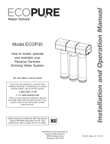
Model RO2050
4-Stage Reverse Osmosis System
INSTALLATION INSTRUCTIONS
English ........................................Pages 3-16
Replacement Parts ................................Page 15
Modelo RO2050
4-Stage Reverse Osmosis System
Instrucciones para la instalación
Español ....................................Páginas 17-31
Repuestos ...................................... Página 30
Modèle RO2050
Système d’osmose inverse à 4 étapes
Instructions d’installation
French .......................................Pages 32-46
Pièces de rechange. . . . . . . . . . . . . . . . . . . . . . . . . . . . . . . Page 45
Tools and
Materials
Required
• Hand or electric drill
• Drill bits: 1/8", 3/16",
1/4" and 3/8"
• Adjustable wrenches
• Pencil
• Slotted and Phillips
screwdrivers
• Tape measure
• File
• Safety glasses
• Towel
• Utility knife
For sinks without extra
hole for faucet:
• Center punch
• Cone-shaped
grinding wheel
• 1-1/4” hole saw or
drill bit
• Safety mask
NOTE: All tools may
not be necessary for
installation. Read
installation procedures
before starting to
determine what tools
are necessary.
Parts Included
• Pre-assembled filter
system (mounting
bracket, membrane
housing, membrane,
pre-and postfilter
housings and
pre- and postfilter
cartridges)
• Reverse osmosis
membrane
• Inlet supply adapter
• Drain clamp
• 1/4" and 3/8" Tubing
• Tank valve
• Storage tank with
stand
• Chrome faucet
• Feed tubing
• Housing wrenches
• Plumber tape
• TDS test kit
• Silicone
System Tested and Certified by NSF International
against NSF/ANSI Standard 58 for the reduction of the
claims specified on the Performance Data Sheet.
System está probado y avalado por NSF International,
según la norma NSF/ANSI 58 para la reducción de
las reclamaciones especificadas en la hoja de datos
de rendimiento.
Le System a été testé et est certifié par NSF
International comme étant conforme à la norme NSF/
ANSI 58 pour la réduction des déclarations spécifiées
sur la feuille des données de performance
Herramientas
y materiales
requeridos
• Taladro eléctrico
o manual
• Brocas: 1/8", 3/16",
1/4" y 3/8"
• Llaves inglesas
• Lápiz
• Destornilladores
planos y Phillips
• Mètre à ruban
• Lima
• Gafas de seguridad
• Toalla
• Cuchillo universal
Para fregaderos sin
orificio adicional para
llave de agua:
• Punzón
• Disco de esmeril
de forma cónica
• Broca común
o broca hueca
cilíndrica de 1-1/4''
• Máscara de seguridad
NOTA: Es posible que
no necesite todas las
herramientas para
la instalación. Lea
los procedimientos
de instalación antes
de comenzar para
determinar qué
herramientas
son necesarias.
Piezas incluidas
• Sistema de filtro
previamente
ensamblado (soporte
de montaje, carcasa
de la membrana,
membrana, carcasas
pre y posfiltro y
cartuchos pre
y posfiltro)
• Membrana de
ósmosis inversa
• Adaptador
de suministro
de entrada
• Abrazadera
de drenaje
• Tubería de 1/4''
y 3/8''
• Válvula del tanque
• Tanque de
almacenamiento
con base
• Llave cromada
• Tubería de
alimentación
• Llaves inglesas
para carcasa
• Cinta de fontanero
• Kit de prueba TDS
• Silicona
Outils et
accessoires
nécessaires
• Perceuse à main
ou électrique
• Forets : 1/8 po, 3/16
po, 1/4 po et 3/8 po
• Clés anglaises
• Crayon de bois
• Tournevis simple
et cruciforme
• Cinta métrica
• Lime
• Lunette de sécurité
• Serviette
• Couteau
Pour éviers sans trou
supplémentaire pour
robinet :
• Pointeau
• Meule conique
• Scie ou foret pour
trou de 1-1/4”
• Masque de sécurité
REMARQUE : Certains
outils peuvent ne pas
être nécessaires pour
l’installation. Lisez les
procédures d’installation
avant de déterminer les
outils nécessaires,
Pièces incluses
• Système de filtre pré-
assemblé (support
de montage, boîtier
de membrane,
membrane, boîtiers
de pré et post-filtre
et cartouches pré
et post-filtre)
• Membrane d’osmose
inverse
• Adaptateur d’arrivée
• Pince de vidange
• Tubes de 1/4 po
et 3/8 po
• Vanne du réservoir
• Réservoir avec
support
• Robinet en chrome
• Tube d’alimentation
• Clés à ergots
• Bande de plombier
• Trousse de test TDS
• Silicone

ENGLISH
• 2 •
OPERATING SPECIFICATIONS
WARNING:
Before installing this reverse osmosis system, make
certain your water supply complies with the following operating
specifications. Failure to do so may reduce the effectiveness of the
system and will void the warranty.
Thin Film Membrane: OM1
Min/Max Pressure: 40–100 psi
Min/Max Temperature: 40°F–100°F
TDS: 2000 ppm
Maximum Hardness
†
: 10 gpg
Sulfide, Iron and Manganese
‡
: <0.1 ppm
Chlorine in Water Supply: <2 ppm
pH Limits: 3–11
Daily Product Water Rate: 9.85 gpd
TDS Rejection: 96.7%
Turbidity: 11 NTU Average
†
If the hardness of your water is above 10 gpg, lime scale will build up rapidly on the
membrane. Scale buildup will plug the membrane and make the system ineffective. We
recommend the installation of a water softener in conjunction with the RO2050 System if
your water hardness is above 10 gpg.
‡
A maximum total level of approximately 0.01 ppm sulfide, iron or manganese is
permissible. See your local dealer or water treatment specialist to reduce these
substances in your water.
PRODUCTION CAPABILITIES
Tested by NSF International according to NSF/ANSI Standard 58 has
given 9.85 gallons per day. Source water test parameters are
50 psig, 77°F, pH of 7.5 ±0.5 and 750 ppm total dissolved solids.
SYSTEM DIMENSIONS
Overall Dimensions: 13-1/2" W x 5-1/2" D x 17-1/4" H
Weight: 17.3 lbs.
Tank Dimensions: 13-1/2" W x 9" D x 9" H
Tank Capacity Max: 2.8 gal.
Tank Air Pressure Empty: 5 to 7 psi
Tank Weight (Full) 28.5 lbs
GENERAL PRECAUTIONS
WARNING:
Do not use with water that is microbiologically unsafe
or of unknown quality without adequate disinfection before or after
the system. Systems certified for cyst reduction may be used on
disinfected waters that may contain filterable cysts.
WARNING:
California Residents - Proposition 65 Warning - This
product contains chemicals known to the State of California to cause
cancer or birth defects or other reproductive harm.
CAUTION:
Filter must be protected against freezing, which can
cause cracking of the filter and water leakage.
CAUTION:
Because of the product’s limited service life and to
prevent costly repairs or possible water damage, we strongly
recommend that the bottom of all plastic housings be replaced every
five years for clear and ten years for opaque. If the bottom of your
housing has been in use for longer than this period, it should be
replaced immediately. Date the bottom of any new or replacement
housing to indicate the next recommended replacement date.
NOTE: Your water must be within required limits for satisfactory
operation. If not, your membrane life may be shortened and your
warranty will be voided (see Specifications).
NOTE: We recommend the installation of a water softener in
conjunction with the RO2050 System if your water hardness is
above 10 gpg.
NOTE: This reverse osmosis system will not protect against disease-
causing bacteria or remove naturally-occurring harmless bacteria.
NOTE: Install on cold water line only.
NOTE: Do not use wicking or sealer to fit connections into the cap of
the filter. Plumber tape is recommended.
NOTE: Make certain that installation complies with all state and local
laws and regulations.
NOTE: The replacement cartridges and reverse osmosis membrane
included with this system have limited service lives. Changes in taste,
odor, and color of the water being filtered indicate that the cartridge
should be replaced (see Replacing the Prefilter and Postfilter
Cartridges, and Replacing the 3rd Stage Reverse Osmosis Membrane).
NOTE: After prolonged periods of non-use (such as during a vacation)
it is recommended that the system be flushed for 5 minutes before it
is used.
NOTE: A drinking water cartridge may contain carbon fines (very fine
black powder). After installation, flush the system for 5 minutes to
remove the carbon fines before using the water.
NOTE: It is recommended that you run the tap at least 20 seconds
prior to using water for drinking or cooking purposes.
NOTE: The contaminants or other substances removed or reduced
by this water treatment device are not necessarily present in your
water.
HOW REVERSE OSMOSIS (RO) WORKS
The RO2050 Reverse Osmosis (RO) System uses a semi-permeable
membrane to reduce dissolved salts and minerals, improving the
taste and odor of your water. The RO membrane is made of layers
of micron-thin film wound around a hollow center core. Water
molecules can pass through the membrane, but dissolved salts and
minerals are rejected.
The RO2050 Reverse Osmosis System features 4-stage filter action.
Your water supply is prefiltered to reduce dirt and chlorine that may
foul the membrane. The RO membrane separates this prefiltered
water into PRODUCT WATER and DRAIN or REJECT WATER.
Incoming water pressure forces the product water through the
membrane and into the storage tank. Dissolved solids and other
contaminants cannot pass through the membrane and are sent to
the drain as reject water. When you open the drinking water faucet,
product water is drawn from the storage tank through an activated
carbon postfilter, providing you with cleaner, great-tasting water.
For each gallon of water produced, several gallons are discharged
as reject water. The storage tank can hold up to 2.8 gallons of water
at a time, for drinking and cooking needs. When used under the
Specifications, your Reverse Osmosis membranes should last 12-24
months.

ENGLISH
• 3 •
INSTALLATION
• Read all installation and operating instructions before installing and
using your RO system.
• For standard, under-sink installation on a 3/8" steel, brass or copper
cold water line.
• Carefully unpack unit and make sure all components are present.
See check list below for the components included with your
system.
1. What's in the Box
Item Qty Description
1 1 Module
2 2 Housings
3 1 Storage tank and tank base
4 1 Sediment cartridge
5 1 Carbon block
6 1 RO membrane
7 1 Plastic bag with parts and faucet
8 1 Plastic bag with two O-rings and
silicone packet
If upon opening your unit you determine that a part is missing,
DO NOT RETURN the unit to the store. Call 800-279-9404.
1
2
3
4
5 6
7
8
2. Install the Water Supply Adapter
• For standard under-sink installation on 1/2" 14 NPS threads or
3/8" x 3/8" compression.
• Please read all instructions and precautions before installing and
using your Filtration System.
• Numbered diagrams correspond with numbered steps.
The supply adapter fits 1/2" - 14 NPS supply threads or 3/8" x 3/8"
compression. If local codes permit, it may be used to connect the
system to the cold water supply line. If local codes do not permit the
use of the supply adapter, alternate connectors can be obtained from
your local supplier.
A) Turn off cold water supply line. If cold water line does not have a
shut-off valve under the sink, you should install one.
B) Turn on the cold water faucet and allow all water to drain from
line.
C) Disconnect riser cold water supply valve.
D) Ensure the sealing gasket is fully seated into the feed adapter
valve female thread.
E) Install feed adapter valve onto supply valve. Hand tighten only.
F) Connect the riser to the feed adapter valve.
NOTE: See Figures 1G-1H for configuring the feed adapter to
3/8" x 3/8" compression connections.
Sealing Gasket
1A
1B
1D
1C
1G
1H

ENGLISH
• 4 •
3. Selecting the Faucet Location
The drinking water faucet should be positioned with function,
convenience, and appearance in mind. An adequate flat area is
required to allow faucet base to rest securely. The faucet fits through
a 1-3/8" hole. Most sinks have pre-drilled 1-3/8" or 1-1/2" diameter
holes that may be used for faucet installation. If these pre-drilled
holes cannot be used or are in an inconvenient location, it will be
necessary to drill a 1-3/8" hole in the sink to accommodate the faucet.
WARNING:
This procedure may generate dust which can cause
severe irritation if inhaled or come in contact with the eyes. The use
of safety glasses and respirator for this procedure is recommended.
WARNING:
Do not attempt to drill through an all-porcelain sink. If
you have an all-porcelain sink, mount the faucet in pre-drilled sprayer
hole or drill through countertop next to sink.
WARNING:
When drilling through a countertop, make sure the
area below the drilled area is free of wiring and piping. Make certain
that you have ample room to make the proper connections to the
bottom of the faucet.
WARNING:
Do not drill through a countertop that is more than
1" thick.
WARNING:
Do not attempt to drill through a tiled, marble,
granite or similar countertop. Consult a plumber or the countertop
manufacturer for advice or assistance.
A) Line the bottom of the sink with newspaper to help prevent
debris, parts or tools from falling into drain.
B) Place masking tape over area to be drilled to help prevent
scratches if drill bit slips.
C) Mark hole with a center punch. Use a 1/4" drill bit to drill the pilot
hole.
D) Use a 1-3/8" drill bit and drill a hole completely through the sink.
E) Smooth rough edges with a file.
C
B
D
A
Figure 1
4. Mounting the Faucet
A) Remove faucet base from faucet by twisting base 1/4 turn. The
rubber washer should be in place below the base. The two toggle
bolts should be inserted through the base and the rubber washer.
The bolts are screwed into the spring-loaded toggle.
B) Place the base assembly over the hole in the sink. The two
toggles should pass through the hole far enough to spring fully
open. If they are not open, unscrew the bolt until the toggle
moves down to clear the sink.
C) Look down through the base for this step. Before tightening
the bolts, determine the correct rotation of the base. The final
position of the handle will be 45 degrees off from the bolt
heads. Use Figure 5 to help determine the best position for your
installation.
Through the hole in the base, hold the toggle in position while
tightening the bolt. The spring loaded toggle will contact the
bottom of the counter top and hold in position. Do not fully tighten.
Repeat for second toggle bolt.
Check the final position of the base and toggle bolts. Tighten the
two bolts evenly. DO NOT OVERTIGHTEN. Tighten only far enough
to prevent the base from rotating when the faucet is rotated in
place.
D) Attach large diameter 3/8" (red) drain tube to the larger barb
fitting at the faucet bottom. This tube should be long enough to
reach the drain clamp in Step 5.
E) Attach small diameter 1/4" (red) brine tube to other barb fitting at
faucet bottom. This tube should be long enough to reach the right
side of the head assembly without kinking or stressing.
F) Locate blue plastic tubing. Slide the compression nut onto the
tubing, followed by the white plastic ferrule. The long tapered end
of the ferrule should face towards the end of the tubing and the
tubing should extend through the ferrule about 1/4". Place white
insert into end of tubing.
G) Insert white plastic tubing into the threaded shaft from the faucet
and hand tighten the compression nut. Using a wrench, tighten
nut 1 to 1-1/2 turns.
H) Check that the O-ring is in place on the faucet. Feed the three
tubes throught the base. Hold the faucet in the final position and
rotate backwards (to the left) while pushing down. The faucet will
drop into the base. Push down on the faucet and rotate forward
(to the right) to lock it into final position. The O-ring will be seated
and the faucet held securely in position.
I) Insert the spout into the top opening. Hold in position and screw
the collar onto the base.
NOTE: If the faucet handle is not in the correct position, remove the
faucet, loosen the toggle bolts and reposition the base. Tighten the
toggle bolts. Then reinstall the faucet.
Base
Black Rubber
Washer
Folds Upward
A
Figure 2

ENGLISH
• 5 •
B
Base
Black Rubber
Washer
Will Spring Open
O-ring Seat
Figure 3
C
Handle Faces This Direction
45°
Notch For Faucet
Blades Must Be Held
When Tightening
Notch For Faucet
Figure 4
D
E
F
G
Figure 5
5. Installing the Drain Clamp
NOTE: If you have a single-basin sink with a disposal unit, call
Customer Support for options.
NOTE: Before installing the drain clamp, check the drainpipes under
the sink for corrosion. Corroded pipes should be replaced before
continuing with installation.
A) Attach the drain clamp to a vertical section of the drainpipe,
about 6" above the trap. Make sure the opening on the drain
clamp is facing towards the drinking water faucet.
B) Using the fitting hole of the drain clamp as a guide, drill a
1/4" hole through one side of the drainpipe.
C) Remove the drain clamp from the drainpipe and enlarge the hole
with a 3/8" drill bit. Use a file to remove rough edges from the
drilled hole.
D) Make sure the black rubber gasket is adhered to the inside of
the drain clamp and place the drain clamp assembly over the
drilled hole. Look through the hole and position the clamp so that
the center of the clamp hole is slightly higher (about 1/16") than
the center of the drilled hole. (See Figure 8). Tighten the clamp
securely.
E) Screw the plastic compression nut onto the drain clamp until
hand-tight.
6"
A
Figure 6
CB
Figure 7
D
E
Figure 8

ENGLISH
• 6 •
6. Installing the Filter Housings and Cartridges
A) Locate two black rubber O-rings and silicone grease in plastic
bag.
B) Lubricate each O-ring with a coating of clean silicone grease.
With two fingers, press each O-ring securely into the groove
below the threads of each housing.
CAUTION:
The rubber O-ring provides the water-tight seal between
the cap and the bottom of the housing. It is improtant that the O-ring
be properly seated in the groove below the threads of the housing or
a water leak could occur.
C) Unwrap cartridges and insert in the bottom of the housings.
Make sure cartridge slips over standpipe in the bottom of the
housing.
NOTE: Be sure to install cartridges in proper housings (see Figure 10).
D) Screw housings onto unit and HAND TIGHTEN ONLY. Do not
over-tighten. Do not use the wrench or other mechanical devices.
The wrench that is provided in the package is only to loosen the
housing when it is time to change the cartridges.
R200
4th Stage Final Postlter
OM1
3rd Stage Membrane
RS14
1st Stage Prelter
CB1
2nd Stage First Postlter
Figure 9
7. Connecting the Faucet to the Drain
NOTE: This is a gravity drain line. Any loops, kinks or sharp bends
must be eliminated before proceeding. Failure to create a straight
line to the drain may result in reject water leaking through the air gap
in the faucet onto the counter top and below the faucet.
A) Align the 3/8" red tubing from the faucet with the compression
nut on the drain clamp. Create as straight a path as possible with
the tubing. Cut the tubing squarely below the nut and remove the
internal and external burrs.
B) Loosen the compression nut two complete turns. Insert the tubing
into the nut until it stops. Tighten with fingers, then tighten 1 to 2
turns with a wrench.
A
B
3/8" Tube
Figure 10
8. Installation of Mounting Screws
A) If system is being installed under the kitchen sink, locate it
on back or right wall. Make sure to allow ample space for
installation (Figure 11). To change the filter cartridges, a minimum
of 1-1/2" of clearance is required underneath the filter housings.
A minimum of 2" of clearance from the left side of the unit is also
required or 5" from the left bracket mounting screw hole.
B) Install mounting screws at least 15" from cabinet floor and 7-1/2"
apart. Leave a 5/16" space between the head of the screw and
the wall to slip bracket onto screws.
NOTE: Each connection fitting on the RO Assembly has a plug that
must be removed before inserting tubing. Push in on the collar and
pull the plug out.
5" (min.)
7
1
/2"
15" (min.)
1
1
/2" (min.)
2" (min.)
Figure 11

ENGLISH
• 7 •
9. Connecting the Faucet to the System
A) Locate the red (1/4") tubing (reject water line) from the drinking
water faucet. This tube is the smaller of the red tubes. Place
a mark on the tubing 5/8" from the end. Moisten the end of the
tubing with water and insert tubing into the quick-connect fitting
on the flow restrictor found on the right side of system behind the
membrane.
If tubing is not firmly connected, leaking will occur. It is important for
the tubing to be inserted all the way until the mark is flush with the
outer edge of the quick-connect insert.
NOTE: Tubing and sanitary inserts may be quickly and easily removed
from the fitting if necessary by pressing the collar around the fitting
then pulling the tubing with your other hand.
B) Insert the 1/4" blue tube from the faucet into the postfilter. The
fitting is at the top left of the RO System.
Sanitary Insert
A
B
Port Reference
Back View
Figure 12
10. Connecting the Storage Tank to the System
CAUTION:
When tank is full, it weighs approximately 28.5 pounds.
Provide ample support under the tank.
A) Remove sanitary cap from top of tank and apply 3 or more wraps
of plumber tape to threads on tank. Thread the tank valve onto
the top of the tank opening and then tighten 1-1/2 to 2 turns with a
wrench. Turn tank so handle is in line with tubing.
CAUTION:
The tank /valve connection will leak if not properly
sealed. Plumber tape will normally seal the threaded connection.
B) Locate the green 1/4" tubing. Place a mark on the tubing 5/8" from
each end. Moisten one end of the tubing with water and insert
with a twisting motion into the port of the tank valve until the 5/8"
mark is flush with the quick connect fitting. Then locate the tank
near the system's installation area.
C) Cut the tubing to correct length. Install free end of tubing into
white quick-connect fitting on the post filter tee on the right side.
Do not cut tubing.
D) Place entire system over mounting screws on wall and slide
down.
CAUTION:
Make certain system is firmly attached to wall to prevent
it from falling and possibly becoming damaged.
NOTE: Use caution not to bend or pinch the tubing behind the system
while attaching to mounting screws.
A
B
1/4" Tube
Apply
plumber
tape
5/8"
Figure 13
Port Reference
Back View
C
Figure 14

ENGLISH
• 8 •
11. Connecting the Supply Adapter and Inlet Filter
A) Locate remaining length of white 1/4" plastic tubing.
B) Push into quick connect fitting on the right side of system.
C) Cut the tube to a length that will allow connection to the cold
water supply fitting. Ensure the tubing does not kink. Push the
tube into the fitting.
A
1/4" Tube
5/8"
5/8"
Figure 15
Port Reference
Back View
B
Figure 16
12. Installing the Membrane
A) Remove tube attached to membrane housing by pressing in the
white collar around the fitting while pulling the tubing with your
other hand.
B) Hold the membrane housing with one hand and turn the cap
(wrench provided) with other hand to remove. To make it easier
to hold the membrane housing, you may want to remove the
postfilter.
With clean hands (sanitary gloves preferred), remove the membrane
from the plastic bag. HANDLE WITH CARE.
CAUTION:
Do not unwrap the tape around the membrane, as it is part
of the membrane. Do not squeeze membrane.
C) Use clean silicone grease (pack is included with the system) to
lubricate both O-rings and the brine seal.
D) With the double O-ring side first, push membrane into housing
until it stops. About 1/8" of the membrane’s plastic core will stick
out beyond the housing.
E) Hand-tighten membrane housing cap until you feel resistance,
then tighten an additional 1/2 turn. Do not over-tighten.
F) Reinsert the tube by pushing it into the quick connect fitting.
D
E
C
Figure 17
Port Reference
Back View
A
Figure 18

ENGLISH
• 9 •
NOTE: Initially, the water may appear cloudy. This is a result of air
trapped in the post-polishing filter. It is not harmful and will disappear
in a matter of minutes. It may take up to a week after installing a new
post-polishing filter for the trapped air to dissipate.
A
Closed
Tank Valve
B
Counter-
clockwise
Open
Tank Valve
Figure 20
15. For California Residents
In your installation kit you will find a label that needs to be applied to
your unit. This label is required by California HSC Section 116835 and
should be applied to your unit after installation.
The system is ready for operation. You can now enjoy
quality water from your Reverse Osmosis System.
TESTING YOUR REVERSE OSMOSIS SYSTEM
Model RO2050 Reverse Osmosis System
Total Dissolved Solids (TDS) Test
NOTE: Under NSF/ANSI Standard 58, it is highly recommended that
you (the consumer) have your water tested at least every 6 months to
verify that your system is performing satisfactorily.
Sampling Instructions:
Sampling instructions are included with the Total Dissolved Solids
(TDS) Test Kit.
Total Dissolved
Solids Test Kit
Figure 21
13. Faucet Operation
A) For water flow, rotate the handle 1/4-turn until it stops.
A
Figure 19
14. System Start-up
NOTE: The reverse osmosis membrane is treated with a food grade
sanitizing agent that may cause an undesirable taste. Although it is
not harmful, it should be flushed from the system.
NOTE: The post-polishing filter may contain fine black carbon
particles. These fines are harmless, but may make the water appear
gray in color. The carbon fines are flushed from the system with the
first tank full of water.
NOTE: The RO system does not produce a high volume of water on
demand as an ordinary filter does. Water is produced at a slow, drop-
by-drop rate. The system requires about 2 to 4 hours to fill the storage
tank. As water is taken from the tank, the system automatically starts
the cycle of replacing the water and then stops water production
when the tank is full.
CAUTION:
Visually check the entire system for leaks. If a leak is
present, see Troubleshooting.
A) Turn off valve at top of storage tank.
B) Turn on the cold water supply.
C) Turn the faucet handle 1/4 turn to the open position and let it drip
for 30 minutes.
D) Completely open the cold water supply until it comes to a stop.
Allow water to drip from the faucet for 24 more hours. Then close
the faucet and open the valve on the storage tank. The tank valve
is open when the handle lines up with the tubing connection.
NOTE: In the normal production of this membrane the use of different
materials and preservatives are used to ensure optimal shelf life of
the unit. As with any drinking water filtration product, we recommend
a thorough 24 hour flush of this element to ensure optimal taste and
water quality.
E) Allow 3 hours for the tank to fill. Again, periodically check the
installation for leaks. After the storage tank is filled, open the
faucet to flush the post-polishing filter. Allow 4 to 5 minutes for all
of the water to drain from the tank.
F) Close faucet and allow tank to fill.
G) Repeat steps E and F four times.

ENGLISH
• 10 •
OPTIONAL INSTALLATION
Connecting your Reverse Osmosis System to Refrigerator
Icemaker /Water Dispenser
CAUTION:
If you are connecting this unit to your refrigerator
icemaker/water dispenser with initial RO installation, wait to turn
on the icemaker until the post-polishing filter has been flushed
according to Step 12.
CAUTION:
Use plastic tubing and fittings. Do not use copper tubing
or brass fittings.
NOTE: For optimum performance, it is recommended that the
distance between the RO system and the refrigerator icemaker/water
dispenser be no greater than 10 feet. At distances greater than 10
feet, the water pressure from the system may not be adequate to
deliver water to the refrigerator.
MATERIALS REQUIRED (available from your local hardware store):
• 1/4" x 1/4" x 1/4" compression or quick-connect tee
• 10 feet of 1/4" polyethylene tubing
• Shut-off valve
1. Turn off refrigerator water supply and icemaker (consult
manufacturer’s guidelines).
2. Close tank valve (on top of storage tank).
3. Turn off water to RO system at the cold water supply.
4. Open drinking water faucet to relieve pressure.
5. Locate tubing (permeate) leading to your drinking water faucet.
Cut and insert the 1/4" x 1/4" x 1/4" compression or quick-connect
tee into the permeate tubing. Consult manufacturer’s guidelines
before installing the supply adapter.
NOTE: When cutting the permeate tubing, you may experience some
water leakage.
6. Using a length of 1/4" polyethylene tubing, connect the
icemaker/dispenser line with the free port on the compression
tee.
7. The shut-off valve should be installed as close to this port of
the tee as possible. Shut-off valve should be installed in the OFF
position. Consult manufacturer’s guidelines before installing the
shut-off valve.
8. Completely open cold water supply.
9. Open tank valve.
10. Turn off the drinking water faucet.
11. Turn on water to RO system at cold water supply.
12. Turn on icemaker and open shut-off valve. Consult manufacturer’s
instructions.
13. Check for leaks and tighten connections if necessary.
1
2
3
4
5
6
7

ENGLISH
• 11 •
REPLACING THE PREFILTER AND POSTFILTER CARTRIDGES
1st Stage Prelter and 2nd Stage Prelter Cartridges:
The cartridge should be replaced every six months. If your water
contains a high amount of sediment, it may be necessary to change
the 1st stage cartridge more frequently. If your water contains a high
amount of chlorine, it may be necessary to change the 2nd stage
prefilter more often.
1. Turn off incoming water supply and valve on the storage tank.
Place a tray under the system to catch any water that spills
during removal of the filter housings.
2. Open faucet to release pressure.
3. Unscrew bottom of filter housings from caps. Use the filter
wrench. Discard used cartridges.
4. Remove black rubber O-rings from grooves in housings. Wipe
grooves and O-rings clean; set O-rings aside.
5. Rinse out housings and fill each 1/3 with water. Add 2
tablespoons of bleach and scrub with non-abrasive brush or
sponge. Rinse thoroughly.
6. Lubricate each O-ring with a coating of clean silicone grease.
With two fingers, press each O-ring securely
into groove below the threads of the
appropriate housing.
CAUTION:
The rubber O-ring
provides the water-tight seal between
the cap and the bottom of the
housing. It is important that the O-ring
be properly seated in the groove
below the threads of the housing or a
water leak could occur.
7. Insert cartridges in the bottom of the housings. Make sure
cartridge slips over standpipe in the bottom of the housing.
NOTE: Be sure to install cartridges in proper housings (see diagram
below).
8. Screw bottoms of housings back onto caps securely; do not over-
tighten. Turn on cold water supply. Check for leaks. Continue to
check periodically to make sure no leaks develop.
4th Stage Postlter Cartridge: postfilter should be replaced every
twelve months.
1. Turn off incoming water supply and valve on the storage tank.
Place a tray under the system to catch any water that spills
during removal of the filter housings.
2. Open faucet to release pressure.
3. Remove filter from bracket and discard.
4. Remove tubes from fittings by pressing in collar around the fitting
while pulling the tubing out with your other hand.
NOTE: The filter has an arrow on it showing the direction of flow.
The tee fitting connects to the inlet side of the filter and the elbow
fitting attaches to the outlet side.
NOTE: Hand tighten fittings, then tighten with wrench 1/4 turn.
5. Attach 4th stage filter to bracket with the tee fitting on the right
hand side.
6. Attach tubes to fittings by pushing in until the tube stops. Check
to see if tube is in place by trying to gently pull tube out.
1/4" White
Feed Tube
1/4" Red Faucet
Drain Tube
3/8" Red Drain
Tube
R200
(4th Stage Final Postfilter)
OM1
(3rd Stage Membrane)
RS14
(1st Stage
Prefilter)
CB1
(2nd Stage
First Postfilter)
1/4" Green
Storage Tank
Permeate Tube
1/4" BlueTube
to Faucet

ENGLISH
• 12 •
REPLACING THE 3RD STAGE REVERSE OSMOSIS MEMBRANE
About the Reverse Osmosis Membrane
When used under operating conditions specified on page 1 of
the manual, your reverse osmosis membrane should last at least
one year. You should replace the membrane after 18 to 24 months.
Replace it sooner if you notice a return of unpleasant tastes or
odors or a noticeable decline in water production. The precise life
span of your system's membrane will depend on the quality of the
water entering the system and the frequency with which you use it.
Frequent system use prevents the filtered salts and minerals from
building up on the membrane as scale. The more water the system is
required to produce, the longer the membrane will last. You may wish
to find a variety of uses for your system in order to prolong the life of
the membrane.
During extended periods of non-use (such as during a vacation),
remove the membrane from the membrane housing and place it in a
sealed plastic bag. Store membrane in refrigerator for future use. DO
NOT FREEZE.
NOTE: If system stands for more than 2 to 3 days without being used,
the storage tank should be emptied.
Replacing the Membrane and Sanitizing the System and Filters
NOTE: It is recommended that you sanitize the system each time
you change the membrane. It is not necessary to sanitize the system
when changing only the prefilters or postfilter.
NOTE: When installing a new membrane, it is recommended that
you replace the prefilter and postfilter cartridges as well.
Removing the Membrane and Filters
1. Turn off the cold water supply. Allow five minutes for system to
depressurize. Place a tray under the system to catch any water
that spills during removal of the filter housings.
2. Open drinking water faucet to drain tank. When tank is drained,
close faucet.
3. Remove tube attached to membrane housing by pressing in the
white collar around the fitting while pulling the tubing with your
other hand.
4. Hold the membrane housing with one hand and remove the cap
using the RO housing wrench included with the system.
5. To remove the RO membrane, grasp membrane tube with pliers
and pull. Discard old membrane. Screw cap back onto membrane
housing. DO NOT install new membrane.
6. Unscrew filter housings from caps and discard used cartridges.
7. Remove black rubber O-rings from grooves in housings. Wipe
grooves and O-rings clean; set O-rings aside.
Sanitizing the System
8. Rinse out bottom of housings and fill each 1/3 with water. Add 2
tablespoons of household bleach to each housing and scrub cap,
bottom of housings, and membrane housing with non-abrasive
sponge or cloth. Rinse thoroughly.
9. Lubricate O-rings with a coating of clean silicone grease. With
two fingers, press each O-ring securely into groove below the
threads of the appropriate housing.
CAUTION:
The rubber O-ring provides the water-tight seal between
the cap and the bottom of the housing. It is important that the O-ring
be properly seated in the groove below the threads of the housing or
a water leak could occur.
10. Screw bottom of housing onto caps WITHOUT inserting prefilters
and hand-tighten. Do not over-tighten.
11. Hand-tighten membrane housing cap until you feel resistance,
then tighten an additional 1/2 turn. Do not over-tighten.
12. Reinsert the tube by pushing it into the quick connect fitting.
13. Open the cold water supply and let the system run for 2 to 3
minutes to carry the bleach solution throughout the system.
14. Close the cold water supply and turn on the drinking water
faucet. Let the faucet run for about 30 seconds before turning off.
15. Let the entire system stand for 30 minutes to sanitize.
16. After 30 minutes, turn on the drinking water faucet to allow the
bleach water to run out (about 3 to 5 minutes).
17. Unscrew bottom of housings. Discard bleach water and rinse.
Replacing the Membrane and Filter Cartridges
To replace the filters, see Replacing the Prefilters and Postfilter.
To replace the membrane, see Step 12: Installing the Membrane.
NOTE: After installing new membrane and cartridges, allow system
to run for 3 hours to fill tank. Check for leaks every hour. As pressure
builds in tank, leaks may occur that did not exist directly after
installation.
When the membrane and cartridges have been changed, follow the
system start-up procedure in Step 14: System Start-up.

ENGLISH
• 13 •
TROUBLESHOOTING GUIDE
Leaks between bottom of housing and cap
1. Ensure sump is tightly screwed to cap. If it still leaks close the
cold water supply and tank valves.
2. Clean black rubber O-ring and lubricate with clean silicone
grease. With two fingers, insert O-ring in groove below threads of
housing and press into place. Tighten housing back onto cap.
3. Open the cold water supply and tank valve. If leaks persist, call
Technical Support.
Leaks on tank valve assembly
1. Open drinking water faucet to drain storage tank. Let drinking
water faucet run until it drips. Turn off cold water supply.
2. Push in on white collar of tank valve fitting and pull out tubing.
Unscrew the tank valve from the storage tank. Rewrap threads
on top of the tank with plumber tape. Screw tank valve back onto
tank. Trim 1/2" from end of tubing and reinsert 5/8" into tank valve
fitting.
3. Open the cold water supply and shut off the reverse osmosis
faucet. Let the system pressurize for several hours and check for
leaks. Check again after tank is fully pressurized.
Leaks on quick-connect ttings
1. Close the cold water supply and tank valve.
2. Depress plastic collar and pull out tubing.
3. Cut off 1" of tubing and place a mark 5/8" from end of tubing.
Tubing should be cut squarely. The internal and external burrs
should be removed.
4. Push tubing 5/8" into fitting.
5. Open the cold water supply and tank valve. If leaks persist, call
Technical Support.
No ow or slow ow from the brine (drain) line
Less than 1½ cups per minute
NOTE: Before checking brine (or reject) flow, make sure the system
is producing water by turning off the valve on the storage tank and
opening the faucet. Water should drip from faucet.
1. Examine the RS14 and CB1 prefilters. If clogged, replace (see
Replacing the Prefilter and Postfilter) and recheck the brine (or
reject) flow rate.
2. If the prefilters are not at fault, the brine (or drain) flow controller
is probably clogged. Call Technical Support.
High TDS in Product Water
If high levels of TDS (Total Dissolved Solids) are detected in your
product water (approximately 30% or greater of what is measured
in your tap water, as determined with a conductivity meter or by the
supplied TDS Test Kit), the RO membrane may need to be replaced, or
the brine (or drain) flow control tubing may be clogged.
Reduced production
Slow or no product water flow usually indicates either a clogged
prefilter or an exhausted membrane. First, replace the prefilters. If
the production rate is not improved, replace membrane.
Gradual return of taste and odor
Gradual return of unpleasant taste and odor over a period of time
may indicate that your filter cartridges and/or RO membrane need to
be replaced. See Replacing the Prefilters and Replacing the Reverse
Osmosis Membrane.
Sudden return of taste and odor
If shortly after complete servicing noticeable taste and odors return,
contact Technical Support.
No water pressure from the drinking water faucet or low volume
in storage tank
1. Close the cold water supply to system.
2. Lift storage tank to see if it is empty. If not, open the drinking
water faucet to empty water from tank.
NOTE: It may be necessary to pump a small amount of air into the
tank with a bicycle pump to remove all the water from the tank.
3. When tank is empty, use a pressure gauge to check tank
pressure. An empty tank should contain 5 to 7 psi pressure.
Increase or decrease the air pressure in the tank accordingly.
4. Open cold water supply. Let system run for 3 hours to fill tank,
then check system performance. If performance has not
improved, call Technical Support.

ENGLISH
• 14 •
PERFORMANCE DATA
Important Notice: Read this performance data and compare the
capabilities of this system with your actual water treatment needs.
It is recommended that before installing a water treatment system,
you have your water supply tested to determine your actual water
treatment needs.
This system has been tested according to NSF/ANSI 58 for the
reduction of the substances listed below. The concentration for the
indicated substances in water entering the system was reduced to
a concentration less than or equal to the permissible limit for water
leaving the system, as specified in NSF/ANSI 58.
NOTE: Substances reduced are not necessarily in your water.
Filter must be maintained according to manufacturer’s instructions,
including replacement of filter cartridges.
Testing was performed under standard laboratory conditions. Actual
performance may vary.
The tested efficiency rating for this system is 6.20%. Efficiency
rating means the percentage of the influent water to the system
that is available to the user as reverse osmosis treated water under
operating conditions that approximate typical daily usage. The tested
recovery rating is 14.57%. Recovery rating means the percentage
of the influent water to the membrane portion of the system that is
available to the user as reverse osmosis treated water when the
system is operated without a storage tank or when the storage tank
is bypassed.
NOTE: This reverse osmosis system contains a replaceable
component critical to the efficiency of the system. Replacement
of the reverse osmosis component should be with one of identical
specifications, as defined by the manufacturer, to ensure the same
efficienty and contaminant reduction performance.
The RO2050 has been tested for the treatment of water containing
pentavalent arsenic [also known as As(V), As(+5), or arsenate]
at concentrations of 0.050 mg/L or less. This system reduces
pentavalent arsenic, but may not remove other forms of arsenic. This
system is to be used on water supplies containing a detectable free
chlorine residual or on water supplies that have been demonstrated
to contain only pentavalent arsenic. Treatment with chloramine
(combined chlorine) is not sufficient to ensure complete conversion
of trivalent arsenic to pentavalent arsenic. Please see the Arsenic
Facts section of the Performance Data Sheet for further information.
Model RO2050
Substance
Average Influent
Concentration
Maximum
Permissible
Product Water
Concentration
Reduction
Requirements
Average
Reduction
Standard 58
Arsenic
(Pentavalent)
0.050 mg/L ± 10% 0.010 mg/L 96.2%
Barium 10.0 mg/L ± 10% 2.0 mg/L 99.0%
Cadmium 0.03 mg/L ± 10% 0.005 mg/L 97.2%
Chromium
(Hexavalent)
0.3 mg/L ± 10% 0.1 mg/L 96.5%
Chromium
(Trivalent)
0.3 mg/L ± 10% 0.1 mg/L 99.4%
Copper 3.0 mg/L ± 10% 1.3 mg/L 98.4%
Fluoride 8.0 mg/L ± 10% 1.5 mg/L 94.8%
Lead 0.15 mg/L ± 10% 0.010 mg/L 97.7%
Radium 226/228 25 pCi/L ± 10% 5 pCi/L 80.0%
Selenium 0.10 mg/L ± 10% 0.05 mg/L 97.8%
Turbidity 11 NTU ± 1 NTU 0.5 NTU 99.1%
Total Dissolved
Solids
750 mg/L ± 40 mg/L 187 mg/L 96.7%
Cysts**
Minimum
50,000/mL
99.95% 99.99%
**NSF/ANSI Standard 58 certified to reduce cysts such as Cryptosporidium and Giardia
by mechanical means.
EPA Est. 082989-CHN-001
Arsenic Fact Sheet
Arsenic (abbreviated As) is found naturally in some well water. Arsenic in water has no color, taste or odor. It must be measured by a lab
test. Public water utilities must have their water tested for arsenic. You can get the results from your water utility. If you have your own well,
you can have the water tested. The local health department or state environmental health agency can provide a list of certified labs. There
are two forms of arsenic: pentavalent arsenic [also called As(V), As(+5), and arsenate] and trivalent arsenic [also called As(III), As(+3) and
arsenite]. In well water, arsenic may be pentavalent, trivalent, or a combination of both. Special sampling procedures are needed for a lab to
determine what type and how much of each type of arsenic is in the water. Check with the labs in your area to see if they can provide this type
of service. Reverse osmosis (RO) water treatment systems do not remove trivalent arsenic from water very well. RO systems are very effective
at removing pentavalent arsenic. A free chlorine residual will rapidly convert trivalent arsenic to pentavalent arsenic. Other water treatment
chemicals such as ozone and potassium permanganate will also change trivalent arsenic to pentavalent arsenic. A combined chlorine residual
(also called chloramine) may not convert all the trivalent arsenic. If you get your water from a public water utility, contact the utility to find out
if free chlorine or combined chlorine is used in the water system. The RO2050 system is designed to remove pentavalent arsenic. It will not
convert trivalent arsenic to pentavalent arsenic. The system was tested in a lab. Under those conditions, the system reduced 0.050 mg/L (ppm)
pentavalent arsenic to 0.010 mg/L (ppm)(the USEPA standard for drinking water) or less. The performance of the system may be different at
your installation. Have the treated water tested for arsenic to check if the system is working properly. The RO component of the RO2050 system
must be replaced every 12-24 months to ensure the system will continue to remove pentavalent arsenic. The component identification and
locations where you can purchase the component are listed in the installation/operation manual.

ENGLISH
• 15 •
REPLACEMENT PARTS
For replacement parts contact your nearest
OMNIFILTER
retailer or
call 1-800-279-9404.
Item
#
Part Number Description QTY
1 244796 Drain Clamp 1
2 4004898 Inlet Supply Adapter 1
3 244857 Faucet 1
4 153049 Housing 2
5 244794 1/4" White Tubing 1
6 244875 1/4" Red Tubing 1
7 EV544700 1/4" Blue Tubing 1
8 244850 1/4" Green Tubing 1
9 244849 3/8" Red Tubing 1
10 144604 Tank Valve (1/4" NPT x 1/4" QC) 1
11 244833 Storage Tank 1
12 244785 Tank Stand 1
13 RS14 1st Stage Sediment Prefilter 1
14 CB1 2nd Stage Prefilter 1
15 OM1 3rd Stage RO Membrane 1
16 R200 4th Stage Postfilter 1
17 OW30 Wrench 1
18 SZ12200338 RO Housing Wrench 1
19 143495 Silicone 1
20 244787 Valve Auto Shut-off 1
21 2GA-MH-EG25 Membrane Housing 1
22 150646 TDS Test Kit 1
* 243250 Screw Kit 1
* 244885 Plumber Tape 1
* 244944 Housing O-ring Kit for 153049 Housings 1
* Not Shown
1
2
3
4
5
6
7
8
9
10
11
12
13 14 15
16
17
18
SILICONELUBRICANT
19
20
21
22
IOWA Residents Only:
Store or seller’s name
Address
City State Zip Telephone
Seller’s Signature Date Customer’s Signature Date

ENGLISH
• 16 •
Limited 3 Year Warranty
Pentair Residential Filtration, LLC (herein after PRF) warrants to the original owner, that (under normal use): Product or part to be free from
defects in material and/or workmanship for three (3) years from the date of purchase. Any replacement products furnished will be free from
material defects in materials and workmanship for the remainder of the original warranty period. This warranty does not cover: (1) filter
cartridges (2) damage due to lightning or other conditions beyond the control of PRF (3) defects not reported within the above stated time
periods, (4) items manufactured by other companies, (5) problems arising from failure to comply with PRF instructions, (6) problems and/
or damage arising from acts of nature, abuse, misuse, negligence or accident by any party other than PRF, (7) problems and/or damage
resulting in whole or in part from alteration, modification, repair or attempted alteration, modification or repair by any party other than PRF,
(8) noncompliance with applicable codes/ordinances.
If a defect in workmanship or materials in a product or part covered by the warranty should arise, PRF, at its sole discretion, will repair or
replace the defective product or part (PRF may consider, in good faith, the customer’s preference).
All claimed defective product must: (1) be authorized for return by PRF with a Return Goods Authorization number (2) include proof of
the purchase date of the product or part (3) returned to PRF prior to the expiration of the applicable warranty period, at the customer’s
expense, shipment pre-paid, (4) be accompanied by a letter detailing the Model Number, Serial Number (if any), and a brief description of
the problem.
TO THE MAXIMUM EXTENT PERMITTED BY APPLICABLE LAW, PRF DISCLAIMS ALL OTHER WARRANTIES, WHETHER EXPRESS OR
IMPLIED, INCLUDING, BUT NOT LIMITED TO, THE IMPLIED WARRANTIES OF MERCHANTABILITY AND FITNESS FOR A PARTICULAR
PURPOSE, WITH REGARD TO THE PRODUCTS, PARTS AND ANY ACCOMPANYING WRITTEN MATERIALS.
To the maximum extent permitted by applicable law, PRF shall not be liable for any damages whatsoever (including, but not limited to, loss
of time, inconvenience, expenses, labor or material charges incurred in connection with the removal or replacement of the product or part,
special, incidental, consequential, or indirect damages for personal injury, loss of business profits, business interruption, loss of business
information, or any other pecuniary loss) arising out of the use of or inability to use the defective products or parts, even if PRF has been
advised of the possibility of such damages.
PRF's maximum liability under any provision of this Limited Warranty shall be limited to the amount actually paid for the product or parts.
NOTE: Because some states do not allow the exclusion or limitation of incidental or consequential damages, the above limitations or
exclusions may not apply.
THIS WARRANTY GRANTS SPECIFIC LEGAL RIGHTS, AND OTHER RIGHTS MAY APPLY. SUCH RIGHTS VARY FROM STATE TO STATE.
Notes • Notas • Remarques

©2019 Pentair Residential Filtration, LLC. All rights reserved. SH247234 Rev G AP19
OMNIFILTER
§
Brookfield, WI 53005 800.279.9404 www.omnifilter.com
§
For a detailed list of where Pentair trademarks are registered,
please visit waterpurification.pentair.com/brands. Pentair
trademarks and logos are owned by Pentair plc or its affiliates.
Third party registered and unregistered trademarks and logos
are the property of their respective owners
.
§
Para obtener una lista detallada dónde están registradas las
marcas comerciales de Pentair, sírvase visitar
waterpurification.pentair.com/brands. Las marcas comerciales
y logotipos de Pentair son propiedad de Pentair plc o sus
filiales. Las marcas comerciales y logotipos registrados y
sin registrar de terceros son propiedad de sus respectivos
propietarios.
§
Pour une liste détaillée des sites de dépôt des marques
commerciales Pentair, veuillez visiter
waterpurification.pentair.com/brands. Les marques
commerciales et les logos Pentair sont la propriété de Pentair
plc ou de ses filiales. Les marques commerciales et déposées
et les logos tiers sont la propriété de leurs détenteurs
respectifs
.
/