507148-01P Issue 1406 Page 7 of 13
or restriction, leakage, corrosion, or other deciencies
which could cause an unsafe condition.
3. Insofar as is practical, close all building doors and
windows between the space in which the appliances
remaining connected to the common venting system
are located and other spaces in the building. Turn on
clothes dryers and any appliance not connected to the
common venting system. Turn on exhaust fans, such
as range hoods and bathroom exhausts, so they will
operate at maximum speed. Do not operate a summer
exhaust fan. Close replace dampers.
4. Following the lighting instructions, place the unit being
inspected in operation. Adjust the thermostat so the
appliance will operate continuously.
5. Test for spillage at the draft control relief opening after
5 minutes of main burner operation. Use the ame of
a match or candle.
6. After it has been determined that each appliance
remaining connected to the common venting system
properly vents when tested as outlined above, return
doors, windows, exhaust fans, replace dampers,
and any other fuel burning appliance to their previous
condition of use.
7. If improper venting is observed during any of the above
tests, the common venting system must be corrected.
See National Fuel Gas Code, ANSI Z223.1 (latest edition)
or CAN/CGA B149.1 & .2 Installation Codes to correct
improper operation of common venting system.
Supply and Return Air Plenum
Secure return air plenum to unit using sheet metal screws.
Follow these procedures when installing supply air plenum:
1. Use sealing strips of berglass.
2. Attach the plenum to the furnace or evaporator cabinet
with sheet metal screws.
3. Both supply and return air plenums shall be square and
at least 18” long. They should be the same dimension
as the furnace opening.
4. Install supply and return air ducts as desired.
Filters
Optional lter rack kit for Upow units:
• R37398C001 - Sized for 24 X 16 X 1/2 lter
Basement
Permanent lters are supplied with these units. To clean
the lters, shake to remove any excess dirt and/or use a
vacuum cleaner. Wash with soapy detergent water and
dry. The lters should be cleaned at least once a month, or
more frequently in unusually dusty environments.
Never leave the access panels to the blower
compartment o or partially open.
Oil Supply and Oil Filter Connection
Continuous lengths of heavy wall copper tubing or steel
pipe are recommended and should be installed under the
oor or near walls to protect from damage. Do not run lines
on oor joists or other reverberating surfaces. Always use
are ttings located in accessible places.
Install a generous capacity oil lter inside building between
the fuel shuto valve and burner. Locate lter and valve
close to burner for easy servicing. An oil lter is required for
all models. A 10-micron lter is recommended.
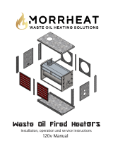
Combustion Chamber
The combustion chamber is installed in the furnace at the
factory. Read the instruction plate on the front of the unit
concerning proper care of the chamber.
This combustion chamber is made of preformed ceramic
ber material. Use extreme care when installing the oil
burner so that the chamber is not damaged around the
burner tube.
Electrical Wiring
All wiring must conform to the National Electrical Code, the
Canadian Electrical Code, and any local codes. Connect
the 115-volt, single phase service to the unit at the
junction box. Use a separate fused branch electrical circuit
containing a properly sized fuse or circuit breaker. Run this
circuit directly from the main switch box to an electrical
disconnect that is readily accessible and located near the
furnace. Follow carefully the wiring diagram adhered to the
inside of the blower compartment door.
The electrical supply to the mechanical vent system
must be supplied from the appliance. All wiring must be
appropriate Class I wiring. Wiring must be installed in rigid
metal conduit, intermediate metal, or be otherwise suitably
protected from physical damage. Refer to the wiring
diagrams supplied with the venter kit for proper electrical
connections.
Thermostat
Locate the thermostat on an inside wall in a room usually
occupied during the day, such as a living room or dining
room, at a height of 4-1/2’ from the oor. Avoid direct
sunlight or supply air from a register. Make sure the location
is not adjacent to appliances such as ovens or lights. Wire
the thermostat with minimum of #18 AWG thermostat wire.
Continuous Blower Operation
The comfort level of the living space can be enhanced
when using this feature by allowing continuous circulation
of air between calls for cooling or heating. The circulation
of air occurs at half the full cooling airow rate. This can
produce more even temperatures throughout the home
and/or continuous operation of IAQ accessories.