Axis 290B User manual

Category
Security camera accessories
Type
User manual

This manual is also suitable for

290B Outdoor housing
Unpacking
In the box with the 290B housing you will find a small plastic bag containing:
No.
1. One large allen key
2. One small allen key
3. Two locking screws
4. Four M8 wall fixings
5. Four plugs (11x50 mm) for use in solid walls
Fitting the camera inside the housing
Recommendation: Fit the camera in indoor conditions to prevent the build-up of dust and
moisture inside the housing.
1. Open the housing by releasing the
two clips on the side.
2. Undo the two screws (6) on the
camera mounting board (7). Slide
the board backwards and lift it
out.
3. Refer to the Axis Installation
Guide provided with the Axis
camera for instructions on camera
hardware installation.
1
2
3
45
6
7
290B Outdoor housing
4. Attach the camera to the camera mounting board (7) using the screw attached to the
board. You will find a screw hole at the bottom of the camera. Before tightening the
screw, position the camera with the board inside the housing (with the lens to the
front) and determine the camera’s correct position.
Caution: The lens should be as close to the window as possible allowing sufficient space between the lens
and window to accommodate the zoom function (if supported).
5. Once the correct position has been established, lift out the camera with the board
while keeping it in the correct position. Tighten the screw at the bottom to securely
affix the camera to the board.
Caution: The heater at the front of the housing unit becomes hot when in operation. If applicable, position
the cable connected from the DC IRIS socket to the lens so that it does not touch the heater.
Caution: Do not over-tighten the screw as you may damage the camera.
6. Position the camera with the board inside the housing as before. Make sure the board
is inserted under the lugs beneath the window in its most forward position. Use the
two screws (6) to secure the board with the camera and lens in the housing.
7. Close the housing with the two clips on the side.
Routing the cables
1. Route the cables (network and power) to the location where the bracket arm is to be
installed.
Note:
The cables can either be routed through the bracket arm (recommended) or through a hole in the base of
the bracket. This hole needs to be drilled in the recess area where the casing metal is thinner to accommo-
date easy drilling.
Determine the size of the hole to accommodate the fitment of the cable gland (not supplied). However, the
hole should not exceed 15mm in diameter.
Warning: Install cable glands and/or cables that are suitable for external use that and are in compliance
with local laws and regulations.
290B Outdoor housing
Installing the housing
Recommendation: Keep the housing closed when possible to prevent the build-up of dust and
moisture inside the housing.
Important: This product should be installed by certified electrical technicians in compliance
with local laws and regulations.
Warning: High voltage. Ensure that the power is disconnected before starting any work or
opening the housing.
If you do not wish to use the included power cable, refer to the following dimension
guidelines:
Maximum power cable length Minimum cable conductor area
330 ft. (100m)
260 ft. (80m)
160 ft. (50m)
100 ft. (30m)
AWG 13 - 0.0040 sq. inch (2.6 mm
2
)
AWG 14 - 0.0031 sq. inch (2.0 mm
2
)
AWG 16 - 0.0020 sq. inch (1.3 mm
2
)
AWG 18 - 0.0012 sq. inch (0.78 mm
2
)
* AWG = American Wire Gauge
Important!
No.
8. Housing
9. White rubber seal
10. Widget
11. Swivel
12. Bracket arm
13. Positioning bolt
9
8
1
12
10
11
13
.
• The white molex connector on the supplied power cable should be connected to
the power supply only and cannot not be routed to the camera housing.
• The cable’s conductor area is proportionate to its length. Using smaller cable
area measurements may seriously damage the unit.
• The maximum power cable length is 330 feet (100 meters).
290B Outdoor housing
1. Detach the bracket from the housing by unscrewing the positioning bolt (13). Use the
large allen key (1) to do this. Continue until the swivel (11) (still attached to the
housing) comes completely loose from the bracket arm (12). The positioning bolt (13)
is held in the bracket arm (12) by a plastic washer inside.
2. Detach the swivel (11) from the housing by loosening its four screws. Use the small
allen key (2) to do this. The four screws are held in the swivel (11) by plastic washers.
3. Position the bracket arm (12) on the wall in the position required and drill four
fixing indicators. Remove the bracket arm and drill the four holes (using an 11 mm
drill bit) to the depth and size (50 mm) of the plugs provided.
4. Route the cables through the rear of the bracket arm and pull them out at the front.
Pull out at least 60 cm of cable to complete the installation.
Warning: Be careful when routing the cables through the bracket arm. A damaged cable may damage the
camera, the housing and/or other system equipment.
5. Position the swivel (11) on the end of the bracket arm (12) with the two cables
coming through the open slot. Ensure that the swivel is positioned with F (front) at
the front and R (rear) at the back.
6. Now position the widget (10) inside the swivel (11) with the cables coming through
the opening. Match the F and R on the widget with the F and R on the swivel,
assuring that F remains at the front and R at the back.
7. Line up the positioning bolt (13) with the screw hole in the widget (10) and tighten it
using the large allen key (1).
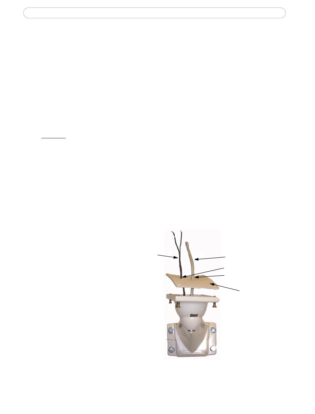
8. Position the white rubber seal (9)
on the flat face of the swivel (11)
by pushing the power cable
through the off centre hole on
the left and the network cable
through the off centre hole on
the right. The two off centre
holes should be positioned
towards the back.
9. Position the housing (8) on the
swivel (11) with the white rubber
seal (9) in-between, the CAT.5
cable going through the larger
hole in the black board and the
power cable going through the
smaller hole. Attach the housing
to the swivel by tightening up
the four screws held in the swivel. Use the small allen key (2) to do this.
Power
Network
Two off centre holes
positioned at the back
9
290B Outdoor housing
Connecting the camera
Warning: Be sure to work inside the housing in dry conditions. Rain water, moisture and prolonged con-
densation inside the housing may cause serious damage to the camera and disturb the picture quality when
in operation.
Warning: High voltage - the apparatus works on 100-240VAC. Always ensure that the power is discon-
nected before starting any work or opening the housing.
1. Open the housing by releasing the two clips on the side.
2. Strip back the mains power cable by 5mm. The minimum cable conductor area for
installation of the housing is 0.5mm
2
.
Warning: Regulations relating to other parts of the system may require a bigger conductor area. You are
responsible that the requirements of these regulations are met.
3. Wire the power cables into the terminal block, the cable
with the “+” sign must be wired as shown (+)
Caution:
Ensure that all wires are correctly and securely wired into
the terminal block. No bare wires should be showing. Tighten the
cable tie so that the power cable is held firmly.
Wiring diagram 290B
4. All models - attach an RJ45 connector (not supplied) to the network cable allowing
sufficient cable to reach the back of the camera. Once you have fitted the connector,
plug it into the network connector at the back of the camera.
AXIS 2420 using a Coaxial cable - attach an RG59 BNC plug to the coaxial cable.
Once you have fitted the BNC plug to the cable connect it to the video output at the
back of the camera.
Important: Only a 90° BNC angle plug will fit inside the housing. Do not use any other plugs!
(+)
Power Network
AXIS 2110/2120
Network Power
AXIS 211
290B Outdoor housing
5. AXIS 2110/2120/211 - plug the green power connector coming from the 12V DC
power supply into the green socket on the camera.
AXIS 2420 - plug the green power connector into the socket labelled I/O-A.
AXIS 211A - replace the 4 pin green power connector coming from the 12V DC power
supply with the 4 pin green terminal block supplied with the camera and connect the
wires:
Power Network
AXIS 2420
AXIS 211A
Network Power
4 pin terminal block
Black/white
wire (-)
wire (+)
Black
AXIS 221 - replace the 4 pin green power connector coming from the 12VDC power
supply with the 3 pin green terminal block supplied with the camera and connect the
wires:
Power Network
3 pin terminal block
Black
Black/white
wire (-)
wire (+)
AXIS 221
290B Outdoor housing
Completing the installation
Caution: The heater at the front of the housing unit becomes hot when in operation. If applicable, position
the cable connected from the DC IRIS socket to the lens so that it does not touch the heater.
Ensure that all cables and connections are correctly and safely installed.
Ensure that the lens setting is correct and make final adjustments if required
(refer to Axis Installation Guide).
Ensure that the window is clean. Wipe it with a dry cloth if it is not. Do not use a
damp or wet cloth! Ensure that no tools/loose parts are left in housing.
Finally ensure that all the visible seals are undamaged and in position.
Warning: If any of the seals are damaged or missing, the housing will not be weatherproof and water
ingress may occur. This can seriously damage to the camera and other system equipment. Installations that
have been completed with damaged or missing seals are not covered by any warranty.
Once you have checked all the above items, close the housing with the two clips on the
side:
1. Loosen the positioning bolt (13)
sufficiently to move the housing
in the desired position. Use the
large allen key (1) to do this. Once
the housing is in its final position
firmly lock up the positioning
bolt (13).
Caution: Do not over-tighten or use exces-
sive force. You may damage the
bracket-swivel assembly if you do so.
2. Finally, securely lock the housing at the front and rear using the locking screws.
3. Connect the white molex connector of the power supply to the power cable. Finish
by connecting the mains cable to the power supply, then the mains cable to the
mains outlet.
Warning: The included power adapter is for indoor use only
The installation is now complete.
Locking screw
at front
290B Outdoor housing
Maintenance
Annual maintenance is required to inspect all visible seals for wear and damage. Worn or
damaged seals should be replaced.
Recommendation: Treat all visible seals with silicone at least once a year to prevent them
from drying out and to aid opening and closing of the housing. Use an all-purpose silicone
spray for use on electrical equipment and components, and also compatible with rubber,
metal and plastic materials.
Clean the housing with a damp cloth only (not on the window). Do not use chemicals to
clean the housing as this may affect the powder coat finish. The window should only be
cleaned with a dry cloth.
Burnt fuses in the fused terminal block can be replaced to reinstate the power supply of the
camera. Use a 5A, 250 V AC fuse and ensure that the mains is disconnected before
beginning.
Specifications
Weight Power requirements Operating temperature
Approx. 6 lbs
(2,75 kg)
AXIS 290B Power adapter (included):
Input voltage: 100-240 (50/60HZ) VAC
Input current Max 1.2A
Max Output Power 50W
Output voltage 15 VDC
Output current 3.4 A
IMPORTANT!
Power adapter is for indoor use only!
AXIS 290B Housing:
Input voltage: 9-15 V DC
Input current:
Max 2.8A at 9V, 3A at 12V, 3.5A at 15V
-4F to 108F (-20°C to +42°C)
Warning: The housing should
not be exposed to many hours
of direct sunlight as this may
overheat and damage the
camera beyond repair. The
maximum temperature inside
the housing should never
exceed 122F (50°C).
Specifications may change without prior notice.
INSTAL GUIDE HOUSING ENV WHITE r3.0 PART NO. 25205
Date: July 2005 COPYRIGHT AXIS COMMUNICATIONS AB 2005
  • Page 1 1
  • Page 2 2
  • Page 3 3
  • Page 4 4
  • Page 5 5
  • Page 6 6
  • Page 7 7
  • Page 8 8

Axis 290B User manual

Category
Security camera accessories
Type
User manual
This manual is also suitable for

Ask a question and I''ll find the answer in the document

Finding information in a document is now easier with AI