Page is loading ...

1
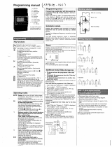
Master clock Sigma C
When receiving goods please check nothing is broken otherwise make a claim near shipping company.
SIGMA
Installation and operating instructions
The document concerns the following products:
907 461 SIGMA C 110-240VAC - wall
907 463 SIGMA C 110-240VAC - rack
BODET SA
BP30001
49340 TREMENTINES
Tél: +33 241 71 72 99
Fax: +33 241 71 72 01
Réf : 607753 C
www.bodet-time.com

2
Table of contents
I - Initial Verification 5
1.1 General information..................................................................................................................5
1.2 Unpacking the master clock.....................................................................................................5
1.3 Cleaning...................................................................................................................................5
II - Safety rules 6
III - Identification - Sigma C 8
3.1 Wall Sigma C ..........................................................................................................................8
3.2 Rack 19’’ Sigma C ..................................................................................................................8
IV - Installation 9
4.1 Mechanical installation.............................................................................................................9
4.1.1 Wall mounted version.........................................................................................................9
4.1.2 Rack 19’’ version................................................................................................................9
4.2 Electrical connections.............................................................................................................10
4.2.1 Wall mounted version.......................................................................................................10
4.2.2 Rack 19’’ version..............................................................................................................10
4.2.3 Connecting a Melodys.....................................................................................................11
4.2.4 Connection of DHF transmitter.........................................................................................11
V - Examples of setting 12
5.1 Setting a DHF time distribution...............................................................................................12
5.2 Programming a RHF circuit....................................................................................................12
5.3 Install an option board............................................................................................................13
VI - Keypad: Key functions 14
6.1 Key functions..........................................................................................................................14
6.2 Synoptic diagram of the programming...................................................................................15
VII - Main menu programming 16
7.1 Standby state.........................................................................................................................16
7.2 User menu.............................................................................................................................16
7.2.1 USB transfer....................................................................................................................16
7.2.2 Add DHF receivers .......................................................................................................17
7.2.3 Bank holidays..................................................................................................................17
7.2.4 Access code....................................................................................................................18
7.2.5 Time and date.................................................................................................................18

3
7.2.6 Dynamic reception...........................................................................................................19
7.2.7 Language.........................................................................................................................19
7.2.8 Version.............................................................................................................................19
VIII - Programming the circuits 20
8.1 Prerequisite before programming circuits...............................................................................20
8.2 Presentation of the circuits.....................................................................................................22
8.3 Viewing the circuits.................................................................................................................21
8.4 Programming the circuits.......................................................................................................21
8.4.1 Add a program step.........................................................................................................22
8.4.2 Delete a program step.....................................................................................................23
8.4.3 Modify a program step....................................................................................................23
8.5 Deleting a program.................................................................................................................23
8.6 Viewing the status of a circuit.................................................................................................23
IX - Manual testing of circuits 24
X - Programming in Holidays and Special Day mode 25
10.1 Prerequisite before programming in holidays and special days..........................................25
10.2 Programme details................................................................................................................25
XI - Technician menu programming 26
11.1 Time synchronisation menu.................................................................................................27
11.1.1 Programmable time changeover....................................................................................28
11.1.2 Setting the time base.....................................................................................................28
11.2 Time output management menu..........................................................................................29
11.3 IP configuration menu..........................................................................................................30
11.4 Relay setting menu..............................................................................................................31
11.5 RHF circuit function setting menu........................................................................................31
11.6 Function setting menu.........................................................................................................32
11.7 “Delete all programming” menu...........................................................................................33
11.8 CPU software download menu............................................................................................33
11.9 Factory setting restoration menu.........................................................................................33
XII - Priority of execution of programs 34
XIII - Alarm messages 35
XIV - Options 37
14.1 Mechanical installation.........................................................................................................37
14.1.1 Wall-mounted version ...................................................................................................37

4
14.1.2 Rack 19’’ version ..........................................................................................................37
14.2 Option board with 3 AFNOR outputs....................................................................................38
14.3 Three inputs option card......................................................................................................38
XV - Technical characteristics 40
XVI - What to do if ...? Check that … 41
Appendix I : NTP programming 42
IP function programming..............................................................................................................42
IP network configuration and protocols supported .....................................................................43
Appendix II : quick start guide 44
Enablinge/disablinge the circuit....................................................................................................44
Test circuits..................................................................................................................................44
Program a holiday or special day period......................................................................................44

5
I - Initial Verification
Thank you for choosing a BODET Sigma C master clock. This product has been carefully
designed for your satisfaction based on ISO9001 quality requirements.
We advise you to read this manual thoroughly before attempting to set up the product.
Please keep this booklet, so that you can refer to it when necessary.
Bodet accepts no responsibility for any issues resulting from any use not conforming
with the guidance in this document.
Any such modication to the product will invalidate the product warrantyee.
1.1 General information
The Sigma C is a master clock which can be used to control slave clocks and heating circuits,
lighting, bell ringing and access to the doors of the building.
The master clock has functions which can be programmed from the technician menu.
On rst installation, it is essential to program the technician menu (see page 26) before the
customer menu.
It is also essential when installing the master clock to program the technician functions in the
order in which they appear in the menu.
This product must be installed in a residential, commercial or light industry environment.
1.2 Unpacking the master clock
Checking the equipment :
■ master clock Sigma C,
■ one USB ash drive,
■ one CD containing the PC software,
■ this manual.
With (option card) :
■ relay card (1 SPDT and 2 SPNO relays) (ref: 907 535).
■ 3 external inputs card (ref: 907 542).
1.3 Cleaning
Use an antistatic product identical to that supplied. Never use alcohol, acetone or other solvents
which may damage the product casing.

6
II - Safety rules
Installation and maintenance of this equipment should only be carried out by qualified personnel.
If the master clock is connected to the 230 V mains power supply, its installation must comply with
the European standard IEC 364 (NFC 15.100 for France).
Protection :
110-230V version: the mains supply for this device must include a neutral phase circuit breaker
of maximum 6 A C curve, rapidly accessible upstream from the supply.
For the relay circuits, add protections with circuit breakers of maximum 4 A. Indicate on the
labels the location of these protections.
The circuit breaker must be switched off during maintenance operation. Refer to labels in the product.
All cables must be attached either to the wall (wall-mounted version) or to the frame of
the cabinet (Rack version) before being connected to the various terminals strips, to
prevent any pulling on these terminal strips. In addition, the wires of each terminal strips
must be attached to each other to maintain the various isolations if an initial fault occurs.
The time distribution cables must not run alongside high power mains cables (to
avoid interference with communication between the master clock and the clocks).
The master clock must be attached (to the wall or rack) before being switched on.
The “RACK” models must be mounted in a 19” cabinet. These components will provide
mechanical, electrical and fire protection (only the front panel may remain accessible).
IMPORTANT: before any installation, refer to the “technical characteristics” paragraph.
Remember to make a backup of your programming on the USB flash drive. In case of incident
(such as breakdown or thunderstorm), you will have to restore the backup to start the time
distribution again.

7
Caution :
In case of replacement of the CR2032 battery, it is
IMPERATIVE to respect the polarity following the
opposite indications.
There is risk of explosion if the battery is replaced by an
incorrect battery.
Please dispose used batteries according to the instructions of
the manufacturer.
To check the model of the master clock,
click key.
-
+
SIGMA C

8
III - Identification - Sigma C
3.1 Wall Sigma C
3.2 Rack 19’’ Sigma C
A
B
C
D
E
USB connector
LCD screen
Alarm indicator light (red LED)
Keypad (see page 15)
Mains indicator light (green LED)
A
B
C
DE
A
B
C
D
E

9
III - Identification - Sigma C
3.1 Wall Sigma C
3.2 Rack 19’’ Sigma C
A
B
C
D
E
USB connector
LCD screen
Alarm indicator light (red LED)
Keypad (see page 15)
Mains indicator light (green LED)
A
B
C
DE
A
B
C
D
E
IV - Installation
4.1 Mechanical installation
Choose a room with low temperature variations away from any source of electrical interference
(contactors, motors, etc.).
4.1.1 Wall mounted version
1/ Loosen the 2 screws on the front.
2/ Remove the top cover: slide upward.
3/ Remove the cover bottom: Press the 2 clips (N) and slide upward.
4/ Disconnect the at cables (Q) (be careful to connect them the same way round on reassembly).
5/ Attach the master clock to the wall.
6/ When your unit is in place, remove the protective lm on the keypad.
4.1.2 Rack 19’’ version
1/ Install the rack in its slot in a cabinet.
Q
N

10
4.2 Electrical connections
4.2.1 Wall mounted version
1/ Connect the cables to the corresponding terminal strips as shown in the gure below.
Meaning of status of LEDs on a RJ45 connector :
- The green LED reects network activity.
The yellow LED indicates the speed of the network:
off=10 Mbps on=100 Mbps.
4.2.2 Rack 19’’ version
The connectors are directly accessible at the rear of the Rack unit.
110-
230VAC
GPS input
F-I or DCF
radio input
External input
See the limit
characteristics of
these circuits on
page 40
Circuit C1
Circuit C2
Circuit C3
DHF output
Output communication
IP connection
RJ45 connector
Attach the wires to each other, near
the terminal strips.

11
4.2.3 Connecting a Melodys :
The Melodys can be connected directly to a relay output of the master clock, an option card or a
wireless relay.
See page 31 to assign the relay to the Melodys, and page 21 for programming.
4.2.4 Connection of the DHF transmitter
DHF transmitter “Time and relays”, reference 907512
.
Power supply depending on
the model (24V or 240V))
Power supply
depending on the
model (24V or 240V)
Power supply
depending on the
model (24V or 240V)
Terminal of the
Melodys
Terminal of the
Melodys
Terminal of the
Melodys
Connection to the
electronic card of the
Sigma
Connection to an
option card of the
Sigma
Connection to a
wireless relay controlled
by the Sigma
Transmitter cable
907512
Yellow
Green
White
Brown

12
V - Examples of setting
5.1 Setting a DHF time distribution
1/ The DHF transmitter must be connected (see page 11).
2/ Turn on the power to the master clock.
3/ Enter the technician menu (see page 26).
4/ Enter the “time output” option.
5/ Select the following with the navigation keys :
- the transmission power (25, 125, 500mW),
- the channel (see instruction manual of the DHF transmitter),
- congure the master clock in INIT mode (all the DHF receivers: slave clocks, repeaters,
etc. must also be in INIT mode),
- when all the slave clocks are synchronised, congure the master clock in START mode
(automatic after 4 hours).
6/ Then, validate your settings by pressing the key.
Note: when adding DHF receivers, you do not have to enter the technician menu. The “Add
DHF receivers” option in the user menu is sufcient.
5.2 Programming a RHF circuit
1/ Install the wireless relay.
2/ Congure the address of the corresponding RHF circuit using the DIP switches from 5 to 8
(default address is 60).
Note : several wireless relays can have the same address as long as control is the same (e.g.
control of outdoor lighting).
3/ In the technician menu, assign the relay (see page 31).
4/ Program the circuit (see page 21).
5/ Place the master clock in INIT mode (see page 17).
6/ Check it works correctly with key.
Note : commands are sent to the wireless relays every hour, any time the programming is modied
and when leaving the menu.
After two hours of no reception, no more steps are executed and the led of the relay turns red.
DHF 03 : INIT ú
125mW canal:2 OK

13
5.3 Install an option board
1/ Switch off the master clock, open it, see page 37.
2/ Install the option board in the slot, x it with the screws provided and put the label in front of it.
3/ Connect the output or input lines of this board.
4/ Close the SIGMA C and switch it on.
please note: in the “Time outputs” technician menu, “DEL” mode is used only to uninstall an
option board from the master clock.
Caution: each Sound module counts for one extension card of the master clock (Max. 2 options
boards).

14
VI - Operating master clock
6.1 Key functions
Keys Functions
Calendar key.
Test key.
Menu key.
Program key.
Correction key.
Validation key.
, , , Navigation keys.
Please note: the exit from the menus is automatic if a key has not been pressed for one minute in
the customer menu or for 5 minutes in the technician menu.

15
6.2 Synoptic diagram of the programming
Choice of
the time
synchronisation
Time output
management
IP
configuration
Relay
assignment
Wireless
relay
assignment
Choice of
master of
slave operation
Activation of
the backlight
Delete all
programming
Update the
system software
Restore
factory setting
Choice of
the state of
the circuit 01
Modification of
the programming
for holidays and
special days
Put in
INIT mode
Load/save
programming
+Technician codepress 5sec
Definition of
bank holidays
Choice of the
Harmonys
programming
Access code
YES/NO
Display of the
radio reception
Choice of
the language
Display of
the system
software version
Setting of
time, date and
time zone
Choice of
the state of
the circuit 02
Choice of
the state of
the circuit 03

16
VII - Main menu programming
7.1 Standby state
In normal operation the master clock displays the time and date :
is the radio signal indicator, which flashes if reception is
poor.
If a bank holiday, a special day or a holiday period has
been programmed on this given day, the master clock
indicates this via a display during the period in which it
applies, with priority management.
7.2 User menu
To access the user menu, press the menu : the key.
Enter the user access code if necessary (see page 18).
Access the menu options using the key and validate
with the key.
The user menu options are :
1/ USB transfer,
2/ Add DHF receivers,
3/ Bank holidays,
4/ Access code,
5/ Time and date,
6/ Dynamic reception,
7/ Language,
8/ Version.
7.2.1 USB transfer
The master clock can load or back up its programming via a
USB ash drive.
Before creating a new programming with the software, you
will need to save the existing one on your USB drive, and
transfer.
Validate the option with the key.
The following screen is displayed :
Insert the USB ash drive and validate with the key.
10:54:32
Mon 08 SEP 2014
10:54:32 BANK DAY
Mon 08 SEP 2014
10:54:32 HOLIDAYS
Mon 08 SEP 2014
USB transfer ok
Add DHF receivers õ
USB transfer ok
Add DHF receivers õ
Connect USB key then
press ok exit C
Restore backup ÷
Create backup ö

17
To load a Program in the master clock :
1/ Validate the option with the key.
The master clock will search for the les available on the
key (.sig extension).
2/ Select the le to be loaded using the and keys.
3/ Validate with the key.
The loading is then carried out. When it is completed, the
unit displays :
To back up the existing Program of the master clock :
1/ Validate the option with the key.
The master clock saves the le with an automatically
allocated name in the format: save1_DD_MM.sig (The
number (1, etc.) and the date are incremented automatically).
It is possible to rename this le from the PC, while
keeping the same “.sig” extension.
Once the backup is completed, the unit displays:
7.2.2 Add DHF receivers
To place the master clock in “DHF initialisation” mode and
enable synchronisation of new equipment :
1/ Validate the initialisation mode with the key.
The following screen is displayed :
2/ Select the “ACTIVE” mode using the and keys
and validate with the key.
The “init” display mode will appear alternately with the normal display during this period (4 hours).
It is possible, once the receivers are DHF initialized, to stop this mode in this menu.
7.2.3 Bank holidays
Bank holidays saved via the PC software (maximum 20 dates) are managed by master clock.
By default, French bank holidays are active.
Bank holidays can be added and congured through the
PC software.
Validate the option with the key.
The following screen is displayed:
Choose YES / NO to activate the bank holidays calendar.
Bank holidays will be considered to be Sundays (the
weekly programming for Sundays will be used on bank
holidays).
Restore: Nest01.02 ú
Confirm ok exit C
Transfer completed
Remove USB key
Create backup
Confirm ok exit C
Transfer completed
Remove USB key
Add DHF receivers ok
Bank Holidays õ
Init mode: ACTIVE ú
Add receivers ok
Bank Holidays ok
Access code õ
Bank Holidays : Yes ú
Sunday prog activated ok

18
7.2.4 Access code
To enter or remove the master clock access code :
1/ Validate the option with the key.
The following screen is displayed :
2/ Choose the option you require and validate it with the
key.
The access code is xed, , , , .
If there are 3 attempts with the wrong access code, an alarm message appears. The keyboard is
locked for 10 minutes. It is possible to unlock it from the technician menu.
7.2.5 Time and date
To change the time or the date of the master clock :
1/ Validate the option with the key.
The following screen is displayed :
2/ You have access to the time zone selection.
The time zone selection allows you to automatically
manage winter/summer time changeovers.
If the zone is not available in the 20 pre-programmed towns
or time zones, select “PROG” mode which is programmed
in the technician menu.
3/ “PROG” mode allows you to congure personalised time zone differences and time
changeovers.
By default it is in “PROG” mode.
4/ The hour is ashing: set the hour using the and
keys and move on to the minutes with the key.
5/ Proceed in the same way for the date.
6/ Validate with the key. If the time has been changed, the seconds are reset to 0.
Access code ok
Time and date õ
Access code: Yes ú
ok
Time and date ok
Dynamic reception õ
Time zone : LONDON ú
(GMT + 00:00) ok
Time zone :PROG ú
(GMT) ok
Time 10:12:00 ú
Date 08/09/14 ok

19
7.2.6 Dynamic reception
To view the dynamic reception of the master clock, validate the option with the key.
If the reception is correct, the time and date will displayed
automatically.
If the master clock is synchronised by a GPS antenna, the
time displayed is GMT.
If the master clock is synchronised by a France-Inter or
DCF antenna, the hour is displayed.
7.2.7 Language
To select the language of the master clock:
1/ Validate the option with the key.
2/ Select the master clock display language from the
different options available.
The languages available are : FRENCH, ENGLISH,
SPANISH, GERMAN, DUTCH, PORTUGUESE,
NORWEGIAN and DANISH.
7.2.8 Version
To view the version of the master clock, validate the option
with the key.
The following screen is displayed :
Dynamic reception ok
Language õ
GMT : 10:12
08/09/14 exit C
10:12
08/09/14 exit C
Language ok
Version õ
Language:ENGLISH ú
ok
Version ok
õ
SIGMA C Version
V1.1E05 31/03/2015 ok

20
VIII - Programming the circuits
8.1 Prerequisite before programming circuits
The programming and set up of Harmonys sounders on the computer network is done on the
software. Please refer to the manual (ref: 607752).
Programming circuits for Melodys and relay (physical or DHF). The different levels of the
programming of these two modes are described below.
8.2 Presentation of the circuits
The master clock has three programmable (hard-wired) circuits allowing contacts (relays) to be
activated.
The option boards allow relays to be added.
See the circuit setting programming in the technician menu on page 31.
The programming circuit menu is accessed by pressing the key.
The programming can be carried out simply on a PC and be imported via the USB port of the
Sigma (see “USB loading and backup”, on page 16).
The conguration of the circuits can be displayed at any time.
Assignment of the relays as a programming circuit or as a melody output is carried out in the
technician menu.
Depending on the requirement, the relay number is therefore a control circuit (no. 1 to 3) or an
HF relay circuit (no. 60 to 75) or an HF melody control circuit (no. 60 to 75 with a musical note
pictogram).
On this screen, you see the rst circuit, its status (Start or
Stop) and the name of this circuit on the second line.
To view the various circuits, continue to press the key.
Use the and keys to select the mode of the circuit.
Description of circuit statuses :
- STOP : program steps not activated.
- START : program active.
- DISPLAY : to view the program steps without modifying them.
- PROG. : to go to circuit programming.
- DELETE : to delete all the program steps of the circuit.
- STATUS : to view the status of the circuit.
To change the name of the circuit, use the key. Use the and keys to select the
characters of this text and validate with the key.
Circuit 01: START ú
Circuit light ok
/