CPU Cards
USER’S MANUAL
VER. 1.2C • SEP 2007
No part of this manual may be reproduced without permission
CEGA Series
PICMG 1.3 Single-Board Computers
Featuring VGA, SATA, RAID, Dual Gb
LAN & IrDA Modules
®
CyberResearch
®
,Inc.
www.cyberresearch.com
25 Business Park Dr., Branford, CT 06405 USA
203-483-8815 (9am to 5pm EST) FAX: 203-483-9024
CEGA PD-32-X: 3.2GHz Pentium D CPU
CEGA PD-36-X
: 3.6GHz Pentium D CPU
CEGA C2-24-X: 2.4GHz Core 2 Duo CPU


CyberResearch
®
CPU Cards CEGA Series
CyberResearch, Inc. iii
25 Business Park Drive P: (203) 483-8815; F: (203) 483-9024
Branford, CT USA www.cyberresearch.com
©Copyright 2007
All Rights Reserved.
September 7, 2007
The information in this document is subject to change without prior notice
in order to improve reliability, design, and function and does not represent
a commitment on the part of CyberResearch, Inc.
In no event will CyberResearch, Inc. be liable for direct, indirect, special,
incidental, or consequential damages arising out of the use of or inability
to use the product or documentation, even if advised of the possibility of
such damages.
This document contains proprietary information protected by copyright.
All rights are reserved. No part of this manual may be reproduced by any
mechanical, electronic, or other means in any form without prior written
permission of CyberResearch, Inc.
Trademarks
“CyberResearch,” and “CEGA Series,” are trademarks of CyberResearch,
Inc. Other product names mentioned herein are used for identification
purposes only and may be trademarks and/or registered trademarks of
their respective companies.
• NOTICE •
CyberResearch, Inc. does not authorize any CyberResearch product for
use in life support systems, medical equipment, and/or medical devices
without the written approval of the President of CyberResearch, Inc. Life
support devices and systems are devices or systems which are intended
for surgical implantation into the body, or to support or sustain life and
whose failure to perform can be reasonably expected to result in injury.
Other medical equipment includes devices used for monitoring, data
acquisition, modification, or notification purposes in relation to life
support, life sustaining, or vital statistic recording. CyberResearch
products are not designed with the components required, are not subject
to the testing required, and are not submitted to the certification required
to ensure a level of reliability appropriate for the treatment and diagnosis of
humans.

CEGA Series CyberResearch
®
CPU Cards
iv ©Copyright 2007 CyberResearch, Inc.
Revision History
Title CyRAQ 06SB Series
Revision # Description Date of Issue
1.1 Initial Release May 10
th
2007
1.2C
Revision – update USB
Functionality/Connectivity
September 7
th
2007

CyberResearch
®
CPU Cards CEGA Series
CyberResearch, Inc. v
25 Business Park Drive P: (203) 483-8815; F: (203) 483-9024
Branford, CT USA www.cyberresearch.com
Packing List
If any of the components listed in the checklist below are missing, please do not proceed
with the installation. Contact CyberResearch, Inc. technical support. Call 203-483-8815
and ask for technical support, fax 203-483-9024 attn: tech support, or e-mail
techsupport@cyberresearch.com
.
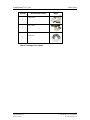
The items listed below should all be included in the CEGA CPU card package.
1 x CEGA single board computer
1 x ATX-12V cable
1 x Mini jumper pack
1 x ATA 66/100 flat cable
4 x SATA cable
2 x SATA power cable
1 x KB/MS Y cable
1 x RS-232 cable (2 COM Ports)
1 x USB cable
1 x Utility CD
Images of the above items are shown in Chapter 3.

CEGA Series CyberResearch
®
CPU Cards
vi ©Copyright 2007 CyberResearch, Inc
Table of Contents
1 INTRODUCTION..................................................................................................... 1
1.1
CEGA OVERVIEW...................................................................................................... 2
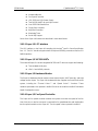
1.1.1 CEGA Features.................................................................................................. 2
1.2 CEGA OVERVIEW...................................................................................................... 3
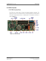
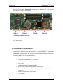
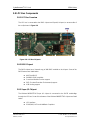
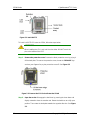
1.2.1 CEGA Overview Photo...................................................................................... 3
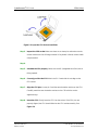
1.2.2 CEGA Peripheral Connectors and Jumpers...................................................... 4
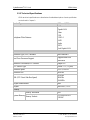
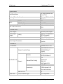
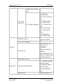
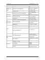
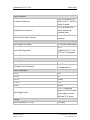
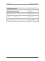
1.2.3 Technical Specifications..................................................................................... 5
2 DETAILED SPECIFICATIONS............................................................................11
2.1 OVERVIEW ............................................................................................................... 12
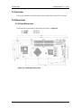
2.2 DIMENSIONS............................................................................................................. 12
2.2.1 Board Dimensions............................................................................................ 12
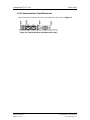
2.2.2 External Interface Panel Dimensions.............................................................. 13
2.3 DATA FLOW.............................................................................................................. 14
2.4 COMPATIBLE PROCESSORS ....................................................................................... 15
2.4.1 CPU Overview................................................................................................. 15
2.4.2 Supported Intel® Core™ 2 Duo Processors ................................................... 15
2.4.3 Supported Intel® Pentium® 4 Processors....................................................... 15
2.4.4 Supported Intel® Pentium® D Processors...................................................... 16
2.4.5 Supported Intel® Celeron® D Processors ...................................................... 16
2.5 INTEL
®
945G NORTHBRIDGE CHIPSET...................................................................... 16
2.5.1 Intel
®
945G Overview...................................................................................... 16
2.5.2 Intel
®
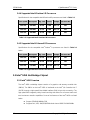
945G Memory Support .......................................................................... 17
2.5.3 Intel
®
945G Serial Digital Video Output (SDVO)............................................ 17
2.5.4 Intel
®
945G Integrated Graphics Media Accelerator 950............................... 18
2.6 INTEL
®
ICH7R SOUTHBRIDGE CHIPSET ................................................................... 19
2.6.1 Intel
®
ICH7R Overview.................................................................................... 19
2.6.2 Intel
®
ICH7R Audio Codec ’97 Controller...................................................... 20
2.6.3 Intel
®
ICH7R IDE Interface............................................................................. 20
2.6.4 Intel
®
ICH7R Low Pin Count (LPC) Interface................................................ 22
2.6.5 Intel
®
ICH7R PCI Interface............................................................................. 22

CyberResearch
®
CPU Cards CEGA Series
CyberResearch, Inc. vii
25 Business Park Drive P: (203) 483-8815; F: (203) 483-9024
Branford, CT USA www.cyberresearch.com
2.6.6
®
ICH7R Real Time Clock................................................................................ 23
2.6.7 Intel
®
ICH7R SATA Controller ........................................................................ 23
2.6.8 Intel
®
ICH7R USB Controller.......................................................................... 23
2.7 PCI BUS COMPONENTS ............................................................................................ 23
2.7.1 PCI Bus Overview............................................................................................ 23
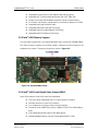
2.7.2 PCI Express (PCIe) Slot Connector................................................................. 23
2.7.3 Broadcom PCIe GbE interface........................................................................ 24
2.8
LPC BUS COMPONENTS ........................................................................................... 25
2.8.1 LPC Bus Overview........................................................................................... 25
2.8.2 BIOS Chipset.................................................................................................... 25
2.8.3 Super I/O Chipset............................................................................................. 25
2.8.3.1 Super I/O LPC Interface ........................................................................... 26
2.8.3.2 Super I/O 16C550 UARTs........................................................................ 26
2.8.3.3 Super I/O Hardware Monitor.................................................................... 26
2.8.3.4 Super I/O Fan Speed Controller................................................................ 26
2.8.3.5 Super I/O Floppy Disk Controller............................................................. 27
2.8.3.6 Super I/O Parallel Port.............................................................................. 27
2.8.3.7 Super I/O Keyboard Controller................................................................. 27
2.9 ENVIRONMENTAL AND POWER SPECIFICATIONS ....................................................... 27
2.9.1 System Monitoring........................................................................................... 27
2.9.2 Operating Temperature and Temperature Control........................................... 28
2.9.3 Power Consumption......................................................................................... 29
3 UNPACKING.......................................................................................................... 30
3.1
ANTI-STATIC PRECAUTIONS...................................................................................... 31
3.2 UNPACKING.............................................................................................................. 31
3.2.1 Unpacking Precautions.................................................................................... 31
3.3 UNPACKING CHECKLIST........................................................................................... 31
3.3.1 Package Contents............................................................................................. 32
4 CONNECTOR PINOUTS...................................................................................... 34
4.1 PERIPHERAL INTERFACE CONNECTORS..................................................................... 35
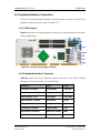
4.1.1 CEGA Layout................................................................................................... 35
4.1.2 Peripheral Interface Connectors ..................................................................... 35
4.1.3 External Peripheral Interface Panel Connectors............................................ 36

CEGA Series CyberResearch
®
CPU Cards
viii ©Copyright 2007 CyberResearch, Inc
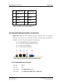
4.2 INTERNAL PERIPHERAL CONNECTORS...................................................................... 36
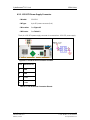
4.2.1 +12V ATX Power Supply Connector ............................................................... 37
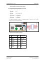
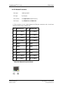
4.2.2 Audio Connector (10-pin)................................................................................ 38
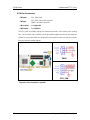
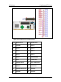
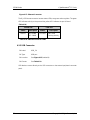
4.2.3 Digital Input/Output (DIO) Connector............................................................ 39
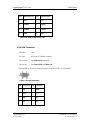
4.2.4 Fan Connectors................................................................................................ 40
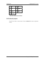
4.2.5 Floppy Disk Connector (34-pin)...................................................................... 41
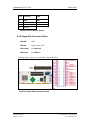
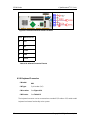
4.2.6 Front Panel Connector (12-pin)...................................................................... 43
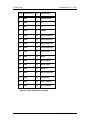
4.2.7 IDE Connector (40-pin)................................................................................... 43
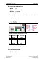
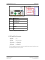
4.2.8 Infrared Interface Connector (5-pin)............................................................... 45
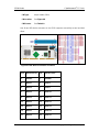
4.2.9 Keyboard Connector........................................................................................ 46
4.2.10 Parallel Port Connector ................................................................................ 47
4.2.11 SATA Drive Connectors.................................................................................. 49
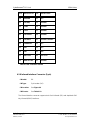
4.2.12 Serial Port Connector (COM1 and COM2)................................................... 51
4.2.13 USB Connectors (Internal)............................................................................ 52
4.3 EXTERNAL PERIPHERAL INTERFACE CONNECTORS................................................... 53
4.3.1 Keyboard/Mouse Connector............................................................................ 53
4.3.2 Ethernet Connector.......................................................................................... 55
4.3.3 USB Connector ................................................................................................ 56
4.3.4 VGA Connector................................................................................................ 57
4.4 ON-BOARD JUMPERS ................................................................................................ 58
5 INSTALLATION .................................................................................................... 59
5.1 ANTI-STATIC PRECAUTIONS...................................................................................... 60
5.2
INSTALLATION CONSIDERATIONS.............................................................................. 61
5.2.1 Installation Notices.......................................................................................... 61
5.2.2 Installation Checklist....................................................................................... 62
5.3 CPU, CPU COOLING KIT AND DIMM INSTALLATION .............................................. 63
5.3.1 Socket LGA775 CPU Installation.................................................................... 63
5.3.2 DIMM Installation........................................................................................... 67
5.4 JUMPER SETTINGS.................................................................................................... 68
5.4.1 Clear CMOS Jumper ....................................................................................... 69
5.5 CHASSIS INSTALLATION............................................................................................ 70
5.5.1 Airflow.............................................................................................................. 70
5.5.2 Backplane Installation..................................................................................... 71
5.5.3 CPU Card Installation..................................................................................... 71

CyberResearch
®
CPU Cards CEGA Series
CyberResearch, Inc. ix
25 Business Park Drive P: (203) 483-8815; F: (203) 483-9024
Branford, CT USA www.cyberresearch.com
5.6 INTERNAL PERIPHERAL DEVICE CONNECTIONS........................................................ 71
5.6.1 Peripheral Device Cables................................................................................ 71
5.6.2 ATA Flat Cable Connection ............................................................................. 72
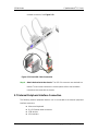
5.6.3 Keyboard/Mouse Y-cable Connector ............................................................... 73
5.6.4 Single RS-232 Cable Connection..................................................................... 74
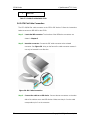
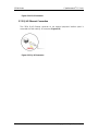
5.6.5 SATA Drive Connection ................................................................................... 75
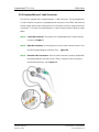
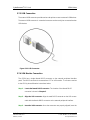
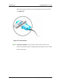
5.6.6 USB Cable Connectors.................................................................................... 77
5.7 EXTERNAL PERIPHERAL INTERFACE CONNECTION ................................................... 78
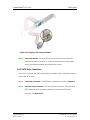
5.7.1 PS/2 Y Cable Connection................................................................................. 79
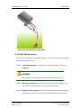
5.7.2 RJ-45 Ethernet Connection.............................................................................. 80
5.7.3 USB Connection............................................................................................... 81
5.7.4 VGA Monitor Connection ................................................................................ 81
6 AMI BIOS................................................................................................................ 83
6.1 INTRODUCTION......................................................................................................... 84
6.1.1 Starting Setup................................................................................................... 84
6.1.2 Using Setup...................................................................................................... 84
6.1.3 Getting Help..................................................................................................... 85
6.1.4 Unable to Reboot After Configuration Changes.............................................. 85
6.1.5 BIOS Menu Bar................................................................................................ 85
6.2 MAIN........................................................................................................................ 86
6.3 ADVANCED............................................................................................................... 87
6.3.1 CPU Configuration.......................................................................................... 88
6.3.2 IDE Configuration........................................................................................... 88
6.3.2.1 IDE Master, IDE Slave ............................................................................. 90
6.3.3 Floppy Configuration....................................................................................... 95
6.3.4 Super IO Configuration ................................................................................... 97
6.3.5 Hardware Health Configuration...................................................................... 99
6.3.6 ACPI Configuration....................................................................................... 101
6.3.6.1 General ACPI Configuration................................................................... 102
6.3.7 APM Configuration........................................................................................ 103
6.3.8 Remote Access Configuration........................................................................ 105
6.3.9 USB Configuration......................................................................................... 106
6.3.9.1 USB Mass Storage Device Configuration............................................... 108
6.4 PCI/PNP..................................................................................................................110

CEGA Series CyberResearch
®
CPU Cards
x ©Copyright 2007 CyberResearch, Inc
6.5 BOOT.......................................................................................................................115
6.5.1 Boot Settings Configuration............................................................................116
6.5.2 Boot Device Priority.......................................................................................118
6.5.3 Removable Drives.......................................................................................... 120
6.6 SECURITY............................................................................................................... 121
6.7 CHIPSET ................................................................................................................. 122
6.7.1 NorthBridge Configuration............................................................................ 123
6.7.2 SouthBridge Chipset Configuration............................................................... 125
6.8 EXIT....................................................................................................................... 127
7 DRIVER INSTALLATION.................................................................................. 129
7.1 AVAILABLE SOFTWARE DRIVERS ............................................................................ 130
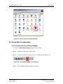
7.2 DRIVER CD AUTO-RUN.......................................................................................... 130
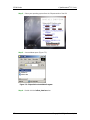
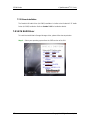
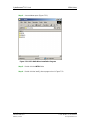
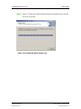
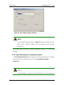
7.3 CHIPSET DRIVER INSTALLATION............................................................................. 131
7.4 INTEL GRAPHICS MEDIA ACCELERATOR DRIVER.................................................... 136
7.5 BROADCOM LAN DRIVER (FOR GBE LAN) INSTALLATION ................................... 141
7.6 REALTEK AC`97 AUDIO DRIVER (ALC665) INSTALLATION................................... 146
7.6.1 BIOS Setup..................................................................................................... 146
7.6.2 Driver Installation ......................................................................................... 146
7.7 REALTEK HD AUDIO DRIVER (ALC883) INSTALLATION........................................ 151
7.7.1 BIOS Setup..................................................................................................... 151
7.7.2 Driver Installation ......................................................................................... 152
7.8 SATA RAID DRIVER.............................................................................................. 152
7.9
IDE CONTROLLER INSTALLATION .......................................................................... 161
A BIOS MENU OPTIONS....................................................................................... 168
A.1 BIOS CONFIGURATION OPTIONS........................................................................... 169
B WATCHDOG TIMER .......................................................................................... 172
C ADDRESS MAPPING.......................................................................................... 175
C.1 IO ADDRESS MAP.................................................................................................. 176
C.2 1ST MB MEMORY ADDRESS MAP.......................................................................... 176
C.3
IRQ MAPPING TABLE ............................................................................................ 177
C.4 DMA CHANNEL ASSIGNMENTS ............................................................................. 177
D DIO INTERFACE................................................................................................. 179

CyberResearch
®
CPU Cards CEGA Series
CyberResearch, Inc. xi
25 Business Park Drive P: (203) 483-8815; F: (203) 483-9024
Branford, CT USA www.cyberresearch.com
D.1 DIO INTERFACE INTRODUCTION ........................................................................... 180
D.2 DIO CONNECTOR PINOUTS ................................................................................... 180
D.3
ASSEMBLY LANGUAGE SAMPLES........................................................................... 181
D.3.1 Enable the DIO Input Function .................................................................... 181
D.3.2 Enable the DIO Output Function.................................................................. 181
E EXTERNAL AC’97 AUDIO CODEC................................................................. 183
E.1
INTRODUCTION ...................................................................................................... 184
E.1.1 Accessing the AC’97 CODEC ....................................................................... 184
E.1.2 Driver Installation......................................................................................... 184
E.2
SOUND EFFECT CONFIGURATION ........................................................................... 185
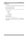
E.2.1 Accessing the Sound Effects Manager........................................................... 185
E.2.2 Sound Effect Manager Configuration Options.............................................. 186
F INTEL
®
MATRIX STORAGE MANAGER...................................................... 189
F.1 INTRODUCTION....................................................................................................... 190
F.1.1 Precautions .................................................................................................... 190
F.2 FEATURES AND BENEFITS ....................................................................................... 190
F.3 ACCESSING THE INTEL
®
MAT RI X STORAGE MANAGER........................................... 191
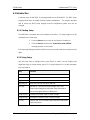
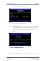
F.4 RAID CONFIGURATION.......................................................................................... 192
F.4.1 Creating a RAID Volume................................................................................ 192
F.4.2 Deleting a RAID Volume................................................................................ 196
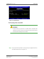
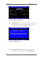
F.4.3 Resetting a Disk to Non-RAID....................................................................... 199
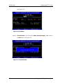
F.4.4 Exiting the Matrix Storage Manager ............................................................. 201
INDEX............................................................................................................................ 203

CEGA Series CyberResearch
®
CPU Cards
xii ©Copyright 2007 CyberResearch, Inc
List of Figures
Figure 1-1: CEGA Overview..........................................................................................................3
Figure 2-1: CEGA Dimensions (mm) .........................................................................................12
Figure 2-2: External Interface Panel Dimensions (mm)...........................................................13
Figure 2-3: Data Flow Block Diagram........................................................................................14
Figure 2-4: 240-pin DIMM Sockets.............................................................................................17
Figure 2-5: PCIe Slot Connector ................................................................................................24
Figure 2-6: LPC Bus Chipsets....................................................................................................25
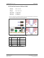
Figure 4-1: Connector and Jumper Locations..........................................................................35
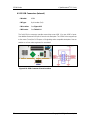
Figure 4-2: +12V ATX Power Connector Location ...................................................................37
Figure 4-3: Audio Connector Location (10-pin)........................................................................38
Figure 4-4: DIO Connector Locations........................................................................................39
Figure 4-5: Fan Connectors Locations......................................................................................40
Figure 4-6: 34-pin FDD Connector Location.............................................................................41
Figure 4-7: Front Panel Connector Pinout Locations..............................................................43
Figure 4-8: IDE Device Connector Locations ...........................................................................44
Figure 4-9: Infrared Connector Pinout Locations ....................................................................46
Figure 4-10: Keyboard Connector Location .............................................................................47
Figure 4-11: Parallel Port Connector Location.........................................................................48
Figure 4-12: SATA Drive Connector Locations........................................................................49
Figure 4-13: Serial Port Connector Pinout Locations..............................................................51
Figure 4-14: USB Connector Pinout Locations........................................................................52
Figure 4-15: CEGA External Peripheral Connector Panel.......................................................53
Figure 4-16: PS/2 Pinout and Configuration.............................................................................54
Figure 4-17: Ethernet Connector ...............................................................................................56
Figure 4-18: VGA Connector ......................................................................................................57
Figure 5-1: Intel LGA775.............................................................................................................64
Figure 5-2: Remove the CPU Socket Protective Shield...........................................................64
Figure 5-3: Open the CPU Socket Load Plate...........................................................................65
Figure 5-4: Insert the LGA775 CPU............................................................................................66
Figure 5-5: Installing a DIMM......................................................................................................67
Figure 5-6: Jumper......................................................................................................................68

CyberResearch
®
CPU Cards CEGA Series
CyberResearch, Inc. xiii
25 Business Park Drive P: (203) 483-8815; F: (203) 483-9024
Branford, CT USA www.cyberresearch.com
Figure 5-7: Clear CMOS Jumper ................................................................................................70
Figure 5-8: IDE Cable Connection .............................................................................................72
Figure 5-9: Keyboard/mouse Y-cable Connection...................................................................74
Figure 5-10: Single RS-232 Cable Installation..........................................................................75
Figure 5-11: SATA Drive Cable Connection..............................................................................76
Figure 5-12: SATA Power Drive Connection.............................................................................77
Figure 5-13: Dual USB Cable Connection.................................................................................78
Figure 5-14: PS/2 Connector ......................................................................................................80
Figure 5-15: RJ-45 Connector....................................................................................................80
Figure 5-16: USB Connector.......................................................................................................81
Figure 5-17: VGA Connector ......................................................................................................82
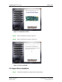
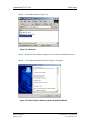
Figure 7-1: Introduction Screen...............................................................................................131
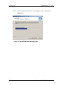
Figure 7-2: Driver Installation...................................................................................................131
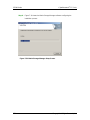
Figure 7-3: Chipset Driver Installation Program ....................................................................132
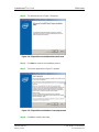
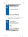
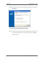
Figure 7-4: Chipset Driver Installation Welcome Screen ......................................................133
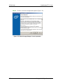
Figure 7-5: Chipset Driver Installation License Agreement..................................................133
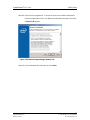
Figure 7-6: Chipset Driver Readme File Information.............................................................134
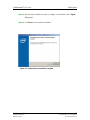
Figure 7-7: Chipset Driver Installation Complete...................................................................135
Figure 7-8: Select the Operating System................................................................................136
Figure 7-9: VGA Driver..............................................................................................................137
Figure 7-10: Intel® Graphics Media Accelerator InstallShield Wizard.................................137
Figure 7-11: InstallShield Wizard Extracting Files.................................................................138
Figure 7-12: Intel® Graphics Media Accelerator Driver Welcome Screen...........................139
Figure 7-13: Intel® Graphics Media Accelerator Driver License Agreement ......................139
Figure 7-14: Intel® Graphics Media Accelerator Driver Installing Notice............................140
Figure 7-15: Intel® Graphics Media Accelerator Installation Complete...............................140
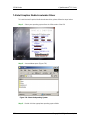
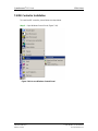
Figure 7-16: Windows Control Panel.......................................................................................141
Figure 7-17: System Icon..........................................................................................................142
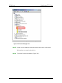
Figure 7-18: Device Manager Tab............................................................................................143
Figure 7-19: Device Manager List............................................................................................144
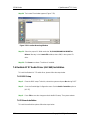
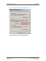
Figure 7-20: Search for Suitable Driver...................................................................................145
Figure 7-21: Locate Driver Files...............................................................................................145
Figure 7-22: Location Browsing Window................................................................................146
Figure 7-23: Select the Audio CODEC.....................................................................................147
Figure 7-24: Locate the Setup Program Icon..........................................................................148

CEGA Series CyberResearch
®
CPU Cards
xiv ©Copyright 2007 CyberResearch, Inc
Figure 7-25: Preparing Setup Screen......................................................................................148
Figure 7-26: InstallShield Wizard Welcome Screen...............................................................149
Figure 7-27: Audio Driver Software Configuration ................................................................149
Figure 7-28: Audio Driver Digital Signal..................................................................................150
Figure 7-29: Audio Driver Installation .....................................................................................150
Figure 7-30: Restart the Computer..........................................................................................151
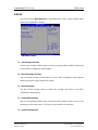
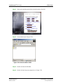
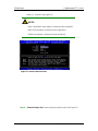
Figure 7-31: SATA RAID Driver Installation Program............................................................153
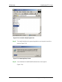
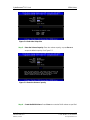
Figure 7-32: SATA RAID Setup Program Icon........................................................................154
Figure 7-33: InstallShield Wizard Setup Screen.....................................................................155
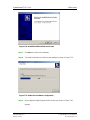
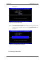
Figure 7-34: Matrix Storage Manager Setup Screen..............................................................156
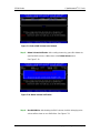
Figure 7-35: Matrix Storage Manager Welcome Screen........................................................157
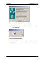
Figure 7-36: Matrix Storage Manager Warning Screen..........................................................157
Figure 7-37: Matrix Storage Manager License Agreement....................................................158
Figure 7-38: Matrix Storage Manager Readme File................................................................159
Figure 7-39: Matrix Storage Manager Setup Complete..........................................................160
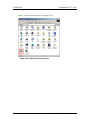
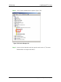
Figure 7-40: Access Windows Control Panel.........................................................................161
Figure 7-41: Double Click the System Icon.............................................................................162
Figure 7-42: Double Click the Device Manager Tab...............................................................163
Figure 7-43: Device Manager List............................................................................................164
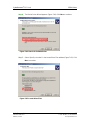
Figure 7-44: Search for Suitable Driver...................................................................................165
Figure 7-45: Locate Driver Files...............................................................................................165
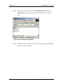
Figure 7-46: Location Browsing Window................................................................................166

CyberResearch
®
CPU Cards CEGA Series
CyberResearch, Inc. xv
25 Business Park Drive P: (203) 483-8815; F: (203) 483-9024
Branford, CT USA www.cyberresearch.com
List of Tables
Table 2-1: Supported Intel® Core™ 2 Duo Processors...........................................................15
Table 2-2: Supported Intel® Pentium® 4 Processors..............................................................15
Table 2-3: Supported Intel® Pentium® D Processors .............................................................16
Table 2-4: Supported Intel
®
Celeron
®
D Processors ................................................................16
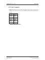
Table 2-5: Supported HDD Specifications ................................................................................21
Table 2-6: Power Consumption..................................................................................................29
Table 3-1: Package List Contents..............................................................................................33
Table 4-1: Peripheral Interface Connectors..............................................................................36
Table 4-2: External Peripheral Interface Panel Connectors....................................................36
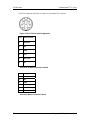
Table 4-3: +12V ATX Power Connector Pinouts.......................................................................37
Table 4-4: Audio Connector Pinouts (10-pin)...........................................................................39
Table 4-5: DIO Connector Pinouts.............................................................................................39
Table 4-6: Fan Connectors Pinouts...........................................................................................41
Table 4-7: 34-pin FDD Connector Pinouts ................................................................................42
Table 4-8: Front Panel Connector Pinouts................................................................................43
Table 4-9: IDE Connector Pinouts .............................................................................................45
Table 4-10: Infrared Connector Pinouts....................................................................................46
Table 4-11: Keyboard Connector Pinouts.................................................................................47
Table 4-12: Parallel Port Connector Pinouts ............................................................................49
Table 4-13: SATA Drive Connector Pinouts..............................................................................50
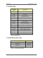
Table 4-14: Serial Port Connector Pinouts ...............................................................................51
Table 4-15: USB Port Connector Pinouts..................................................................................53
Table 4-16: Keyboard Connector Pinouts.................................................................................54
Table 4-17: Mouse Connector Pinouts......................................................................................54
Table 4-18: Ethernet Connector Pinouts...................................................................................55
Table 4-19: Ethernet Connector LEDs.......................................................................................56
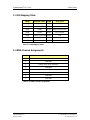
Table 4-20: USB Connector Pinouts..........................................................................................57
Table 4-21: VGA Connector Pinouts..........................................................................................58
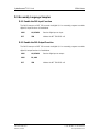
Table 5-1: Jumpers......................................................................................................................68
Table 5-2: Clear CMOS Jumper Settings...................................................................................69
Table 5-3: Cables Provided with CEGA.....................................................................................72

CEGA Series CyberResearch
®
CPU Cards
xvi ©Copyright 2007 CyberResearch, Inc
Table 6-1: BIOS Navigation Keys...............................................................................................85

CyberResearch
®
CPU Cards CEGA Series
CyberResearch, Inc. xvii
25 Business Park Drive P: (203) 483-8815; F: (203) 483-9024
Branford, CT USA www.cyberresearch.com
List of BIOS Menus
BIOS Menu 1: Main......................................................................................................................86
BIOS Menu 2: Advanced.............................................................................................................88
BIOS Menu 3: CPU Configuration..............................................................................................88
BIOS Menu 4: IDE Configuration................................................................................................89
BIOS Menu 5: IDE Master and IDE Slave Configuration..........................................................91
BIOS Menu 6: IDE Master and IDE Slave Configuration..........................................................95
BIOS Menu 7: Super IO Configuration ......................................................................................97
BIOS Menu 8: Hardware Health Configuration.......................................................................100
BIOS Menu 9: ACPI Configuration...........................................................................................101
BIOS Menu 10: General ACPI Configuration ..........................................................................102
BIOS Menu 11: Advanced Power Management Configuration.............................................103
BIOS Menu 12: Remote Access Configuration ......................................................................105
BIOS Menu 13: USB Configuration..........................................................................................106
BIOS Menu 14: USB Mass Storage Device Configuration.....................................................108
BIOS Menu 15: PCI/PnP Configuration ...................................................................................111
BIOS Menu 16: Boot..................................................................................................................116
BIOS Menu 17: Boot Settings Configuration..........................................................................116
BIOS Menu 18: Boot Device Priority Settings ........................................................................119
BIOS Menu 19: Removable Drives...........................................................................................120
BIOS Menu 20: Security............................................................................................................121
BIOS Menu 21: Chipset.............................................................................................................122
BIOS Menu 22:NorthBridge Chipset Configuration...............................................................123
BIOS Menu 23: SouthBridge Chipset Configuration .............................................................125
BIOS Menu 24:Exit.....................................................................................................................127

CEGA Series CyberResearch
®
CPU Cards
xviii ©Copyright 2007 CyberResearch, Inc
Glossary
AC ’97 Audio Codec 97
ACPI Advanced Configuration and Power Interface
APM Advanced Power Management
ARMD ATAPI Removable Media Device
ASKIR Amplitude Shift Keyed Infrared
ATA Advanced Technology Attachments
BIOS Basic Input/Output System
CFII Compact Flash Type 2
CMOS Complementary Metal Oxide Semiconductor
CPU Central Processing Unit
Codec Compressor/Decompressor
COM Serial Port
DAC Digital to Analog Converter
DDR Double Data Rate
DIMM Dual Inline Memory Module
DIO Digital Input/Output
DMA Direct Memory Access
EIDE Enhanced IDE
EIST Enhanced Intel SpeedStep Technology
FDD Floppy Disk Drive
FDC Floppy Disk Connector
FFIO Flexible File Input/Output
FIFO First In/First Out
FSB Front Side Bus
IrDA Infrared Data Association
HDD Hard Disk Drive
IDE Integrated Data Electronics
I/O Input/Output
ICH7R I/O Controller Hub 7
L1 Cache Level 1 Cache
L2 Cache Level 2 Cache

CyberResearch
®
CPU Cards CEGA Series
CyberResearch, Inc. xix
25 Business Park Drive P: (203) 483-8815; F: (203) 483-9024
Branford, CT USA www.cyberresearch.com
LCD Liquid Crystal Display
LPT Parallel Port Connector
LVDS Low Voltage Differential Signaling
MAC Media Access Controller
OS Operating System
PCI Peripheral Connect Interface
PIO Programmed Input Output
PnP Plug and Play
POST Power On Self Test
RAM Random Access Memory
SATA Serial ATA
S.M.A.R.T Self Monitoring Analysis and Reporting Technology
SPD Serial Presence Detect
S/PDI Sony/Philips Digital Interface
SDRAM Synchronous Dynamic Random Access Memory
SIR Serial Infrared
UART Universal Asynchronous Receiver-transmitter
USB Universal Serial Bus
VGA Video Graphics Adapter

CEGA Series CyberResearch
®
CPU Cards
xx ©Copyright 2007 CyberResearch, Inc
Page is loading ...
Page is loading ...
Page is loading ...
Page is loading ...
Page is loading ...
Page is loading ...
Page is loading ...
Page is loading ...
Page is loading ...
Page is loading ...
Page is loading ...
Page is loading ...
Page is loading ...
Page is loading ...
Page is loading ...
Page is loading ...
Page is loading ...
Page is loading ...
Page is loading ...
Page is loading ...
Page is loading ...
Page is loading ...
Page is loading ...
Page is loading ...
Page is loading ...
Page is loading ...
Page is loading ...
Page is loading ...
Page is loading ...
Page is loading ...
Page is loading ...
Page is loading ...
Page is loading ...
Page is loading ...
Page is loading ...
Page is loading ...
Page is loading ...
Page is loading ...
Page is loading ...
Page is loading ...
Page is loading ...
Page is loading ...
Page is loading ...
Page is loading ...
Page is loading ...
Page is loading ...
Page is loading ...
Page is loading ...
Page is loading ...
Page is loading ...
Page is loading ...
Page is loading ...
Page is loading ...
Page is loading ...
Page is loading ...
Page is loading ...
Page is loading ...
Page is loading ...
Page is loading ...
Page is loading ...
Page is loading ...
Page is loading ...
Page is loading ...
Page is loading ...
Page is loading ...
Page is loading ...
Page is loading ...
Page is loading ...
Page is loading ...
Page is loading ...
Page is loading ...
Page is loading ...
Page is loading ...
Page is loading ...
Page is loading ...
Page is loading ...
Page is loading ...
Page is loading ...
Page is loading ...
Page is loading ...
Page is loading ...
Page is loading ...
Page is loading ...
Page is loading ...
Page is loading ...
Page is loading ...
Page is loading ...
Page is loading ...
Page is loading ...
Page is loading ...
Page is loading ...
Page is loading ...
Page is loading ...
Page is loading ...
Page is loading ...
Page is loading ...
Page is loading ...
Page is loading ...
Page is loading ...
Page is loading ...
Page is loading ...
Page is loading ...
Page is loading ...
Page is loading ...
Page is loading ...
Page is loading ...
Page is loading ...
Page is loading ...
Page is loading ...
Page is loading ...
Page is loading ...
Page is loading ...
Page is loading ...
Page is loading ...
Page is loading ...
Page is loading ...
Page is loading ...
Page is loading ...
Page is loading ...
Page is loading ...
Page is loading ...
Page is loading ...
Page is loading ...
Page is loading ...
Page is loading ...
Page is loading ...
Page is loading ...
Page is loading ...
Page is loading ...
Page is loading ...
Page is loading ...
Page is loading ...
Page is loading ...
Page is loading ...
Page is loading ...
Page is loading ...
Page is loading ...
Page is loading ...
Page is loading ...
Page is loading ...
Page is loading ...
Page is loading ...
Page is loading ...
Page is loading ...
Page is loading ...
Page is loading ...
Page is loading ...
Page is loading ...
Page is loading ...
Page is loading ...
Page is loading ...
Page is loading ...
Page is loading ...
Page is loading ...
Page is loading ...
Page is loading ...
Page is loading ...
Page is loading ...
Page is loading ...
Page is loading ...
Page is loading ...
Page is loading ...
Page is loading ...
Page is loading ...
Page is loading ...
Page is loading ...
Page is loading ...
Page is loading ...
Page is loading ...
Page is loading ...
Page is loading ...
Page is loading ...
Page is loading ...
Page is loading ...
Page is loading ...
Page is loading ...
Page is loading ...
Page is loading ...
Page is loading ...
Page is loading ...
Page is loading ...
Page is loading ...
Page is loading ...
Page is loading ...
Page is loading ...
Page is loading ...
Page is loading ...
Page is loading ...
Page is loading ...
Page is loading ...
Page is loading ...
Page is loading ...
Page is loading ...
Page is loading ...
Page is loading ...
Page is loading ...
Page is loading ...
Page is loading ...
Page is loading ...
Page is loading ...
Page is loading ...
Page is loading ...
Page is loading ...
Page is loading ...
Page is loading ...
Page is loading ...
Page is loading ...
Page is loading ...
Page is loading ...
Page is loading ...
Page is loading ...
Page is loading ...
Page is loading ...
Page is loading ...
-
 1
1
-
 2
2
-
 3
3
-
 4
4
-
 5
5
-
 6
6
-
 7
7
-
 8
8
-
 9
9
-
 10
10
-
 11
11
-
 12
12
-
 13
13
-
 14
14
-
 15
15
-
 16
16
-
 17
17
-
 18
18
-
 19
19
-
 20
20
-
 21
21
-
 22
22
-
 23
23
-
 24
24
-
 25
25
-
 26
26
-
 27
27
-
 28
28
-
 29
29
-
 30
30
-
 31
31
-
 32
32
-
 33
33
-
 34
34
-
 35
35
-
 36
36
-
 37
37
-
 38
38
-
 39
39
-
 40
40
-
 41
41
-
 42
42
-
 43
43
-
 44
44
-
 45
45
-
 46
46
-
 47
47
-
 48
48
-
 49
49
-
 50
50
-
 51
51
-
 52
52
-
 53
53
-
 54
54
-
 55
55
-
 56
56
-
 57
57
-
 58
58
-
 59
59
-
 60
60
-
 61
61
-
 62
62
-
 63
63
-
 64
64
-
 65
65
-
 66
66
-
 67
67
-
 68
68
-
 69
69
-
 70
70
-
 71
71
-
 72
72
-
 73
73
-
 74
74
-
 75
75
-
 76
76
-
 77
77
-
 78
78
-
 79
79
-
 80
80
-
 81
81
-
 82
82
-
 83
83
-
 84
84
-
 85
85
-
 86
86
-
 87
87
-
 88
88
-
 89
89
-
 90
90
-
 91
91
-
 92
92
-
 93
93
-
 94
94
-
 95
95
-
 96
96
-
 97
97
-
 98
98
-
 99
99
-
 100
100
-
 101
101
-
 102
102
-
 103
103
-
 104
104
-
 105
105
-
 106
106
-
 107
107
-
 108
108
-
 109
109
-
 110
110
-
 111
111
-
 112
112
-
 113
113
-
 114
114
-
 115
115
-
 116
116
-
 117
117
-
 118
118
-
 119
119
-
 120
120
-
 121
121
-
 122
122
-
 123
123
-
 124
124
-
 125
125
-
 126
126
-
 127
127
-
 128
128
-
 129
129
-
 130
130
-
 131
131
-
 132
132
-
 133
133
-
 134
134
-
 135
135
-
 136
136
-
 137
137
-
 138
138
-
 139
139
-
 140
140
-
 141
141
-
 142
142
-
 143
143
-
 144
144
-
 145
145
-
 146
146
-
 147
147
-
 148
148
-
 149
149
-
 150
150
-
 151
151
-
 152
152
-
 153
153
-
 154
154
-
 155
155
-
 156
156
-
 157
157
-
 158
158
-
 159
159
-
 160
160
-
 161
161
-
 162
162
-
 163
163
-
 164
164
-
 165
165
-
 166
166
-
 167
167
-
 168
168
-
 169
169
-
 170
170
-
 171
171
-
 172
172
-
 173
173
-
 174
174
-
 175
175
-
 176
176
-
 177
177
-
 178
178
-
 179
179
-
 180
180
-
 181
181
-
 182
182
-
 183
183
-
 184
184
-
 185
185
-
 186
186
-
 187
187
-
 188
188
-
 189
189
-
 190
190
-
 191
191
-
 192
192
-
 193
193
-
 194
194
-
 195
195
-
 196
196
-
 197
197
-
 198
198
-
 199
199
-
 200
200
-
 201
201
-
 202
202
-
 203
203
-
 204
204
-
 205
205
-
 206
206
-
 207
207
-
 208
208
-
 209
209
-
 210
210
-
 211
211
-
 212
212
-
 213
213
-
 214
214
-
 215
215
-
 216
216
-
 217
217
-
 218
218
-
 219
219
-
 220
220
-
 221
221
-
 222
222
-
 223
223
-
 224
224
-
 225
225
-
 226
226
-
 227
227
-
 228
228
-
 229
229
-
 230
230
-
 231
231
-
 232
232
-
 233
233
-
 234
234


CyberResearch CEGA PD-36-X User manual
- Type
- User manual
- This manual is also suitable for
Ask a question and I''ll find the answer in the document
Finding information in a document is now easier with AI
Related papers
-
CyberResearch MXGE Series User manual
-
-
-
-
-
-
-
-
-