ESAB m3® plasma Water Injection Control User manual
- Category
- Welding System
- Type
- User manual

WATER INJECTION CONTROL
WIC
Instruction Manual
0558009491 08/2013

This equipment will perform in conformity with the description thereof contained in this manual and accompa-
nying labels and/or inserts when installed, operated, maintained and repaired in accordance with the instruc-
tions provided. This equipment must be checked periodically. Malfunctioning or poorly maintained equipment
should not be used. Parts that are broken, missing, worn, distorted or contaminated should be replaced imme-
diately. Should such repair or replacement become necessary, the manufacturer recommends that a telephone
or written request for service advice be made to the Authorized Distributor from whom it was purchased.
This equipment or any of its parts should not be altered without the prior written approval of the manufacturer.
The user of this equipment shall have the sole responsibility for any malfunction which results from improper
use, faulty maintenance, damage, improper repair or alteration by anyone other than the manufacturer or a ser-
vice facility designated by the manufacturer.
BE SURE THIS INFORMATION REACHES THE OPERATOR.
YOU CAN GET EXTRA COPIES THROUGH YOUR SUPPLIER.
These INSTRUCTIONS are for experienced operators. If you are not fully familiar with the
principles of operation and safe practices for arc welding and cutting equipment, we urge
you to read our booklet, “Precautions and Safe Practices for Arc Welding, Cutting, and
Gouging,” Form 52-529. Do NOT permit untrained persons to install, operate, or maintain
this equipment. Do NOT attempt to install or operate this equipment until you have read
and fully understand these instructions. If you do not fully understand these instructions,
contact your supplier for further information. Be sure to read the Safety Precautions be-
fore installing or operating this equipment.
CAUTION
USER RESPONSIBILITY
READ AND UNDERSTAND THE INSTRUCTION MANUAL BEFORE INSTALLING OR OPERATING.
PROTECT YOURSELF AND OTHERS!

TABLE OF CONTENTS
Section / Title Page
1.0 Safety Precautions ......................................................................................5
1.1 Safety - English ....................................................................................5
1.2 Safety - Spanish....................................................................................9
1.3 Safety - French....................................................................................13
2.0 Description ............................................................................................19
2.1 Functions and Features ...........................................................................19
2.2 Functions and Features (Pump Module) .......................................................... 20
2.3 Technical Specications...........................................................................21
2.4 Connections, Controls and Indicators............................................................. 22
3.0 Installation............................................................................................ 23
3.1 Mounting Hole Locations ........................................................................ 23
3.2 Cut Water Requirements ......................................................................... 23
4.0 Operation............................................................................................. 25
4.1 Operation in CAN Communication Mode ......................................................... 25
4.2 Operation in Optional Control Mode ..............................................................27
4.3 Motor Precaution .................................................................................27
4.4 Anti-freezing Function ........................................................................... 28
4.4.1 Anti-freezing Procedure ........................................................................ 28
4.5 Back Pressure Regulator (BPR) Manifold Assembly................................................. 30
5.0 Maintenance...........................................................................................31
5.1 Troubleshooting with ESAB Vision 5x CNC .........................................................31
5.2 Troubleshooting of CAN Communication ..........................................................32
5.3 S1 and S2 Address ................................................................................33
5.4 Faults and Errors ................................................................................. 34
5.5 Power Requirement...............................................................................35
5.6 Flow Sensor Replacement........................................................................ 36
5.7 Pump Filter Replacement .........................................................................37
6.0 Replacement Parts .................................................................................... 39
6.1 General.......................................................................................... 39
6.2 Ordering ........................................................................................ 39
6.3 WIC Parts........................................................................................ 39
6.4 Hoses and Cables................................................................................ 40
6.5 Recommended Wall Mounted Filter Assembly .....................................................42
6.6 Back Pressure Regulator (BPR) Assembly ...........................................................42

4
TABLE OF CONTENTS

5
SECTION 1 SAFETY PRECAUTIONS
1.0 Safety Precautions
1.1 Safety - English
WARNING: These Safety Precautions are
for your protection. They summarize pre-
cautionary information from the references
listed in Additional Safety Information sec-
tion. Before performing any installation or operating
procedures, be sure to read and follow the safety precau-
tions listed below as well as all other manuals, material
safety data sheets, labels, etc. Failure to observe Safety
Precautions can result in injury or death.
PROTECT YOURSELF AND OTHERS --
Some welding, cutting, and gouging
processes are noisy and require ear
protection. The arc, like the sun, emits
ultraviolet (UV) and other radiation
and can injure skin and eyes. Hot metal can cause
burns. Training in the proper use of the processes
and equipment is essential to prevent accidents.
Therefore:
1. Always wear safety glasses with side shields in any
work area, even if welding helmets, face shields, and
goggles are also required.
2. Use a face shield tted with the correct lter and
cover plates to protect your eyes, face, neck, and
ears from sparks and rays of the arc when operating
or observing operations. Warn bystanders not to
watch the arc and not to expose themselves to the
rays of the electric-arc or hot metal.
3. Wear ameproof gauntlet type gloves, heavy long-
sleeve shirt, cuess trousers, high-topped shoes,
and a welding helmet or cap for hair protection, to
protect against arc rays and hot sparks or hot metal.
A ameproof apron may also be desirable as protec-
tion against radiated heat and sparks.
4. Hot sparks or metal can lodge in rolled up sleeves,
trouser cus, or pockets. Sleeves and collars should
be kept buttoned, and open pockets eliminated from
the front of clothing.
5. Protect other personnel from arc rays and hot
sparks with a suitable non-ammable partition or
curtains.
6. Use goggles over safety glasses when chipping slag
or grinding. Chipped slag may be hot and can y far.
Bystanders should also wear goggles over safety
glasses.
FIRES AND EXPLOSIONS -- Heat from
ames and arcs can start res. Hot
slag or sparks can also cause res and
explosions. Therefore:
1. Remove all combustible materials well away from
the work area or cover the materials with a protec-
tive non-ammable covering. Combustible materials
include wood, cloth, sawdust, liquid and gas fuels,
solvents, paints and coatings, paper, etc.
2. Hot sparks or hot metal can fall through cracks or
crevices in oors or wall openings and cause a hid-
den smoldering re or res on the oor below. Make
certain that such openings are protected from hot
sparks and metal.“
3. Do not weld, cut or perform other hot work until the
workpiece has been completely cleaned so that there
are no substances on the workpiece which might
produce ammable or toxic vapors. Do not do hot
work on closed containers. They may explode.
4. Have re extinguishing equipment handy for instant
use, such as a garden hose, water pail, sand bucket,
or portable re extinguisher. Be sure you are trained
in its use.
5. Do not use equipment beyond its ratings. For ex-
ample, overloaded welding cable can overheat and
create a re hazard.
6. After completing operations, inspect the work area
to make certain there are no hot sparks or hot metal
which could cause a later re. Use re watchers when
necessary.
7. For additional information, refer to NFPA Standard
51B, "Fire Prevention in Use of Cutting and Welding
Processes", available from the National Fire Protec-
tion Association, Batterymarch Park, Quincy, MA
02269.
ELECTRICAL SHOCK -- Contact with
live electrical parts and ground can
cause severe injury or death. DO NOT
use AC welding current in damp areas,
if movement is conned, or if there is
danger of falling.

6
SECTION 1 SAFETY PRECAUTIONS
1. Be sure the power source frame (chassis) is con-
nected to the ground system of the input power.
2. Connect the workpiece to a good electrical
ground.
3. Connect the work cable to the workpiece. A poor
or missing connection can expose you or others
to a fatal shock.
4. Use well-maintained equipment. Replace worn or
damaged cables.
5. Keep everything dry, including clothing, work
area, cables, torch/electrode holder, and power
source.
6. Make sure that all parts of your body are insulated
from work and from ground.
7. Do not stand directly on metal or the earth while
working in tight quarters or a damp area; stand
on dry boards or an insulating platform and wear
rubber-soled shoes.
8. Put on dry, hole-free gloves before turning on the
power.
9. Turn o the power before removing your gloves.
10. Refer to ANSI/ASC Standard Z49.1 (listed on
next page) for specic grounding recommenda-
tions. Do not mistake the work lead for a ground
cable.
ELECTRIC AND MAGNETIC FIELDS
— May be dangerous. Electric cur-
rent owing through any conduc-
tor causes localized Electric and
Magnetic Fields (EMF). Welding and
cutting current creates EMF around welding cables
and welding machines. Therefore:
1. Welders having pacemakers should consult their
physician before welding. EMF may interfere with
some pacemakers.
2. Exposure to EMF may have other health eects which
are unknown.
3. Welders should use the following procedures to
minimize exposure to EMF:
A. Route the electrode and work cables together.
Secure them with tape when possible.
B. Never coil the torch or work cable around your
body.
C. Do not place your body between the torch and
work cables. Route cables on the same side of
your body.
D. Connect the work cable to the workpiece as close
as possible to the area being welded.
E. Keep welding power source and cables as far
away from your body as possible.
FUMES AND GASES -- Fumes and
gases, can cause discomfort or harm,
particularly in conned spaces. Do
not breathe fumes and gases. Shield-
ing gases can cause asphyxiation.
Therefore:
1. Always provide adequate ventilation in the work area
by natural or mechanical means. Do not weld, cut, or
gouge on materials such as galvanized steel, stain-
less steel, copper, zinc, lead, beryllium, or cadmium
unless positive mechanical ventilation is provided.
Do not breathe fumes from these materials.
2. Do not operate near degreasing and spraying opera-
tions. The heat or arc rays can react with chlorinated
hydrocarbon vapors to form phosgene, a highly
toxic gas, and other irritant gases.
3. If you develop momentary eye, nose, or throat ir-
ritation while operating, this is an indication that
ventilation is not adequate. Stop work and take
necessary steps to improve ventilation in the work
area. Do not continue to operate if physical discom-
fort persists.
4. Refer to ANSI/ASC Standard Z49.1 (see listing below)
for specic ventilation recommendations.

7
SECTION 1 SAFETY PRECAUTIONS
5. WARNING: This product, when used for welding
or cutting, produces fumes or gases
which contain chemicals known to
the State of California to cause birth
defects and, in some cases, cancer.
(California Health & Safety Code
§25249.5 et seq.)
CYLINDER HANDLING -- Cylinders,
if mishandled, can rupture and vio-
lently release gas. Sudden rupture
of cylinder, valve, or relief device can
injure or kill. Therefore:
1. Use the proper gas for the process and use the
proper pressure reducing regulator designed to
operate from the compressed gas cylinder. Do not
use adaptors. Maintain hoses and ttings in good
condition. Follow manufacturer's operating instruc-
tions for mounting regulator to a compressed gas
cylinder.
2. Always secure cylinders in an upright position by
chain or strap to suitable hand trucks, undercar-
riages, benches, walls, post, or racks. Never secure
cylinders to work tables or xtures where they may
become part of an electrical circuit.
3. When not in use, keep cylinder valves closed. Have
valve protection cap in place if regulator is not con-
nected. Secure and move cylinders by using suitable
hand trucks. Avoid rough handling of cylinders.
4. Locate cylinders away from heat, sparks, and ames.
Never strike an arc on a cylinder.
5. For additional information, refer to CGA Standard P-1,
"Precautions for Safe Handling of Compressed Gases
in Cylinders", which is available from Compressed
Gas Association, 1235 Jeerson Davis Highway,
Arlington, VA 22202.
EQUIPMENT MAINTENANCE -- Faulty or
improperly maintained equipment can
cause injury or death. Therefore:
1. Always have qualied personnel perform the instal-
lation, troubleshooting, and maintenance work.
Do not perform any electrical work unless you are
qualied to perform such work.
2. Before performing any maintenance work inside a
power source, disconnect the power source from
the incoming electrical power.
3. Maintain cables, grounding wire, connections, power
cord, and power supply in safe working order. Do
not operate any equipment in faulty condition.
4. Do not abuse any equipment or accessories. Keep
equipment away from heat sources such as furnaces,
wet conditions such as water puddles, oil or grease,
corrosive atmospheres and inclement weather.
5. Keep all safety devices and cabinet covers in position
and in good repair.
6. Use equipment only for its intended purpose. Do
not modify it in any manner.
ADDITIONAL SAFETY INFORMATION -- For
more information on safe practices for
electric arc welding and cutting equip-
ment, ask your supplier for a copy of
"Precautions and Safe Practices for Arc
Welding, Cutting and Gouging", Form
52-529.
The following publications, which are available from
the American Welding Society, 550 N.W. LeJuene Road,
Miami, FL 33126, are recommended to you:
1. ANSI/ASC Z49.1 - "Safety in Welding and Cutting"
2. AWS C5.1 - "Recommended Practices for Plasma Arc
Welding"
3. AWS C5.2 - "Recommended Practices for Plasma Arc
Cutting"
4. AWS C5.3 - "Recommended Practices for Air Carbon
Arc Gouging and Cutting"

8
SECTION 1 SAFETY PRECAUTIONS
5. AWS C5.5 - "Recommended Practices for Gas Tung-
sten Arc Welding“
6. AWS C5.6 - "Recommended Practices for Gas Metal
Arc Welding"“
7. AWS SP - "Safe Practices" - Reprint, Welding Hand-
book.
8. ANSI/AWS F4.1, "Recommended Safe Practices for
Welding and Cutting of Containers That Have Held
Hazardous Substances."
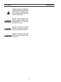
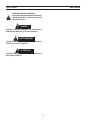
MEANING OF SYMBOLS - As used
throughout this manual: Means Atten-
tion! Be Alert! Your safety is involved.
Means immediate hazards which,
if not avoided, will result in im-
mediate, serious personal injury
or loss of life.
Means potential hazards which
could result in personal injury or
loss of life.
Means hazards which could result
in minor personal injury.
Page is loading ...
Page is loading ...
Page is loading ...
Page is loading ...
Page is loading ...
Page is loading ...
Page is loading ...
Page is loading ...

17
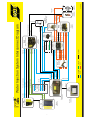
POWER
DATA
LIQUID Optional
Phone 1-843-664-5550
Email: [email protected]
0558009782-OR
GAS
PS
CC-IC
PS-IC
PS & CC Control Cable
Power Cable
Pilot Arc Cable
Coolant Supply Hose
Ext. E-Stop
Digital I/O
(Must be 230V
with
AHC)
Ext. 115/230V
IFH-IC
RAS-TC IN
Air
N
2
O
2
CH
4
H
35
Ar
SGC-A/C OUT
SGC-SG
SGC-PWR
SGC-PG1
SGC-PG2
SGC-Air
SGC-N
2
SGC-O
2
SGC-CH
4
GFA-Air
GFA-N
2
GFA-O
2
GFA-CH
4
RAS-E-Stop
RAS-CAN
Power, Pilot Arc, Coolant
RAS -VDR
AHC- AC IN
AHC-CAN
WIC-H
2
O
OUT
AHC
Air Curtain
Hose
Shield Gas Hose
Plasma Gas
Hose
PGC-PG1
PGC-PG2
PGC-H
35
PGC-Ar
PGC-CAN
PN 05580 07515
IFH-RAS CAN
IFH-AC2
IFH-AHC CAN
IFH-WIC CAN
IFH-SGC CAN
IFH-PGC CAN
IFH-AC1
RAS-TC OUT
RAS-PA
RAS-E(
-)
RAS-PSC
PS-PA
PS-E(
-
)
PS-PSC
Coolant Return Hose
MMI-IC
GFA-H
35
GFA-A
r
SGC-CAN
SGC-AC IN
SGC-A/C IN
CC-TC OUT
CC-TC IN
IFH-IC
IFH-AC IN
Manual
0558008526
Manual
0558008526
Manual
0558007823
Manual
0558008527
Manual
0558008527
Manual
0558008527
Manual
0558006404
PT-36 Torch
SGC
(Shield Gas Control)
RAS
(Remote Arc Starter)
PGC
(Plasma Gas Control)
CC
(Coolant Circulator)
PS
(Power Supply)
IFH
(Interface Hub)
MMI
(Vision 50P)
Manual
0560946014 (A6) or
0560946015 (B4)
PGC-PWR
Air Curtain
Customer
CNC
GFA
(Gas Filter
Assembly)
R
IFH-TDF
Remote -TDF
AHC-VDR
Water Injection System Interconnect Diagram
BPR
(Back Pressure
Regulator)
WIC
(Water Injection
Control)
230V AC
Manual
0558008527
Manual
0558009491
WIC-Air IN (optional)
WIC-H
2O IN
WIC-AC IN
WIC-CAN
Page is loading ...

19
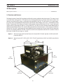
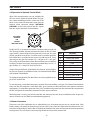
2.0 Description
SECTION 2 DESCRIPTION
15.0”
(381 mm)
18.3”
(465 mm)
8.6”
(218 mm)
18.3”
(465 mm)
6.4”
(163 mm)
6.4”
(163 mm)
12.1”
(307 mm)
Water Injection Control ..................................................................................................................................................................0558009370
The Water Injection Control (WIC) regulates the ow of cut water supplied to the plasma torch. This water is used
as a shield in the cutting process. This shield assists in forming the plasma arc and also cools the cut surface. The
selection and output of cut water is performed and controlled by the CNC. The WIC consists of a water regula-
tor, pump and a closed feedback loop between proportional valve and ow sensor. This is controlled by a local
Process Control Unit (PCU). When used with a cutting machine having ESAB Vision 5X CNC, it sends command
signals to the PCU through the CAN bus. If using other CNC’s, the WIC is used in Optional Control Mode (refer to
Optional Control Mode section). This controls the proportional and solenoid valves. Similar to the m3 Shield Gas
Control (SGC), the WIC is monitored and sends feedback signals through the CAN bus to the CNC for diagnostic
purposes by selecting dierent SDP les. The WIC can be used in conjunction with the SGC to select a wet cut
(cut water as shield) or dry cut (gas as a shield).
Option 1: Wet cut using the WIC and the Plasma Gas Control (PGC). The WIC provides 24 VDC and 24 VAC
power for the PGC.
Option 2: Wet or dry cut (SGC + PGC or WIC + PGC). The SGC provides the 24 VDC and 24 VAC power for the
PGC.
2.1 Functions and Features

20
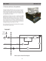
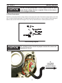
2.2 Functions and Features (Pump Module)
The Pump Module of the WIC consists of a pressure regula-
tor (REG), a pump (P1), a pressure transducer (PT1), a propor-
tional valve (PV1), and a ow sensor (FS) connected in series
as shown below. The lter and the valves are optional and
are supplied by the customer.
The ltered and softened cut water is supplied to the H2O
IN connection at greater than 20 psi (1.4 bar). The pressure
regulator reduces the water pressure to 20 psi (1.4 bar) (fac-
tory set) and sends it to the pump. The pump can increase
the cut water pressure by 150 psi (10.4 bar) (factory set)
above the inlet pressure, thus water after pump should have
an approximate pressure of 170 psi (11.7 bar).
By monitoring the ow, the PCU inside the WIC can regulate
the water ow to a given value.
SECTION 2 DESCRIPTION
Water Injection Control Flow Diagram
Customer Supplied
Components
H2O
PR1
P1/
M1
PT1
PV1/
PWM
FS1
AIR
H2O OUT
IN
IN
(OPTIONAL AIR SUPPLY)
(Valve open
during purge)
EXHAUST
VALVE
WATER
VALVE
FILTER
TO TORCH
CV1
CV2
SOL1
BPR
FILTER

21
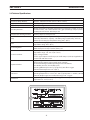
Dimensions (Electrical module) 163 mm x 307 mm x 163 mm (6.4 in x 12.1 in x 6.4 in)
Dimensions (Pump Module) 465 mm x 465 mm x 218 mm (18.3 in x 18.3 in x 8.6 in)
Weight (Electrical module) 15 lb. dry (6.8 kg)
Weight (Pump Module) 60 lb. dry (27.2 kg)
Water Requirements
Soft tap water with an allowable water hardness of <10 ppm as CaCO3 or less, l-
tered at 5 microns, and a minimum ow rate 1 gpm (3.8 l/min) @ at 20 psi (1.4 bar).
Resistivity must be at least 15 k ohm per cm.
Air Supply (anti-freezing function) 250 CFH @ 80 psi (7.1 cmh @ 5.5 bar)
Pump
Positive displacement, rotary vane with adjustable bypass valve (250 psi / 17.2 bars
maximum), CW rotation, Capacity: 1.33 GPM @ 150 psi (5.04 l/min @ 10.3 bars),
Nominal speed: 1725 rpm, Temperature rating: 150
o
F (66
o
C)
Motor
1/2 HP, 230 VAC single phase, 50/60 Hz, 1725/1425 RPM, 3.6A,
Temperature rating: 150
o
F (66
o
C)
Pressure Regulator
Inlet water pressure: 100 psi (6.9 bar) maximum
Outlet water pressure: 20 psi (1.4 bar) factory set
Pressure Transducer
Maximum pressure range: 0 - 200 psi (0 - 13.8 bar)
Temperature range: -40 - 257
o
F (-40
- 125
o
C)
Supply voltage: 24 VDC
Pressure signal output: 4 mA for 0 psi, 20 mA for 200 psi (13.8 bar). Regulated to 1
to 5 VDC with 250 ohm resistor.
Proportional Valve
Supply voltage: 24 VDC
Full load current: 500 mA, Input control signal: 0-10 VDC.
Coil: Standard Voltage: 24 VDC, Operating current: 100-500 mA,
Valve: Orice size: 3/32”, Cv:0.14 (fully open)
Operating dierential pressure: 115 psi (8.0 bar) ; Max. ow 1.5 gpm
Maximum uid temperature: 150
o
F (66
o
C)
Flow Sensor
Maximum operating pressure: 200 psi (13.8 bar),
Operating temperature: -4 - 212
o
F (-20
- 100
o
C), Input power: 5 - 24 VDC @ 50 mA
maximum, Output signal: 58 - 575 Hz, Flow range: 0.13 - 1.3 gpm
Air Solenoid
Supply voltage: 24 VDC, Maximum operating pressure: 140 psi (9.7 bar) , Operating
temperature: 32 - 77
o
F (0 - 25
o
C)
2.3 Technical Specications
SECTION 2 DESCRIPTION

22
SECTION 2 DESCRIPTION
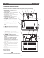
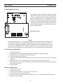
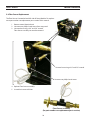
2.4 Connections, Controls and Indicators
The following descriptions of connections, controls and indicators will be useful in operation.
A. On/O Switch – This switch controls the
input power on/o.
B. Power On Light - This light illuminates when
the input power to the unit is on.
C. Pressure Sensor - Pressure transducer signal
input and 24 VDC supply.
D. Proportional Valve – Proportional valve
control signal and 24 VDC supply.
E. Air Solenoid - 24 VDC supply to solenoid
to purge water out of hoses for anti-freeze
purposes.
F. Flow Sensor – Flow sensor signal input and
24 VDC supply.
G. Pump Power – Output 230 VAC to motor.
Power is turned on/o by the control pro-
gram.
B
A
C D E
J
H
G
F
K
H. *AIR – Air input for anti-freeze purposes only.
J. *Water OUT – Cut water output to the torch.
K. *Water IN – Cut water input from the supply.
L. **Optional Control – This is an auxiliary
control used only for Optional Control Mode, if
CAN is not available.
M. *CAN - CAN connection.
N. **24 VAC/DC - 24 VAC power output for
Plasma Gas Control, if Shield Gas Control is not
available.
This port is used only when the customer
wants to cut with water as shield all the
time, thus the shield gas control, (SGC) is not
required. In this case the WIC is required to
provide 24 VDC/AC power to the plasma gas
control (PGC).
O. Fuses – 10A, slow blow fuse for complete unit
protection. 1A, slow blow fuse is for 24 VAC
output only.
P. * AC In - Power supply (230 VAC) to the com-
plete unit.
Q. Ground Stud – Connect the machine chassis
to this stud.
L
M
N
O
P
Q
Note:
Chassis must be connected to the machine ground.
WIC
WATER INJECTION CONTROL
PRESSURE
SENSOR
PROPORTIONAL
VALVE
AIR
SOLENOID
FLOW
SENSOR
ON
OFF
PUMP
POWER
AIR
FREEZE PROTECTION
OPTIONAL
CONTROL
CAN
24 VAC/DC
AC IN
10A
1A
FUSE
* Required connections
** Optional connections

23
SECTION 3 INSTALLATION
3.0 Installation
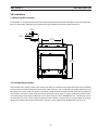
3.1 Mounting Hole Locations
Install the WIC in an appropriate location to maintain adequate and unrestricted airow into and out of the cabi-
netry. For permanent mounting, please refer to the gure below for mounting hole dimensions.
3.2 Cut Water Requirements
The customer must supply a clean water source to the WIC to maximize consumable life. Water must be ltered
to a low level of calcium carbonate (measured in water hardness). This is critical for the proper performance of
the nozzle in the torch. Excessive deposits of calcium carbonate on the nozzle will alter water ow and produce
an unstable arc. Hardness of the water at the torch must be less than 2 ppm. If using a conductivity meter to mea-
sure water purity, the recommended level is: Resistivity must be at least 200,000 ohm•cm, conductivity can be
no more than (5 µ S/cm). Source water may require a water softener, reverse osmosis system or other de-ionizing
equipment to obtain this low level of hardness. Consult a water specialist for detailed advice in this area.
16.75”
425.45 mm
10.28”
261.11 mm
.50”
12.7 mm
.281”
7.137 mm

24
SECTION 3 INSTALLATION

25
SECTION 4 OPERATION
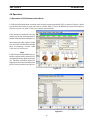
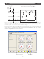
4.0 Operation
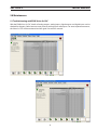
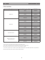
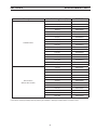
In CAN Communication Mode, customer needs to select a water injection le (SDP) as shown in Figure 4.1. Make
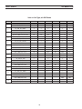
sure to select the correct gas type with water as a shield. Table 4.1 shows all dierent gas types used in the m3
G2 plasma system. Gas type 13 and 14 are used for water injection.
Figure 4.1
Figure 4.2
4.1 Operation in CAN Communication Mode
If the selection is conrmed in the pa-
rameter screen, the recommended wa-
ter ow will be displayed (see gure 4.2).
After selecting the le, perform “shield
test” and water will then ow through
torch. If everything is correct, select
“cycle start” to start plasma.
Note:
In CAN Communication Mode only, wa-
ter ow command will increase by 25%
automatically during shield test and dry
run. Therefore, actual ow will be 25%
higher than the commanded ow from
the CNC during shield test and dry run.
Page is loading ...

27
SECTION 4 OPERATION
4.2 Operation in Optional Control Mode
When CAN communications are not available, the
WIC can work in Optional Control Mode. This hap-
pens when retrotting an older system with PT-36
torch. In this mode, all commands come from the
external 10-pin connector labeled “OPTIONAL
CONTROL” on the back panel of the WIC. Signals
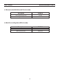
from this 10-pin connector are listed below:
PIN Function
A +24 VDC (OUT)
B External Anti-freeze
C CNC COM
D Fault
E External Reference COM
F External Flow Reference
G Water Flow Output
H Water Pressure Output
J +24 VDC (from Pin A)
K Chassis
Pin A (+24 VDC) is an output to customer. Customer needs to send +24
VDC through pin B to activate anti-freeze function. Pin D is the fault
signal, which is normal high and the signal level is from pin C. In case
of fault, pin D will reset to low. Customer needs to monitor pin D for
fault. Water ow is provided to the system via pin E and pin F. Every
one volt gives 0.2 gpm, for example: 5V = >1.0 gpm or 1V = >0.2 gpm.
The system can also provide the water ow and water pressure back to
customer. For these two signals, the mapping relationships are: 5V = >1
gpm for ow, 5V = >100 psi (6.9 bar) for pressure.
Outputs from pin D (Fault), pin G (Water Flow Output), and pin H (Wa-
ter Pressure Output) are available in both CAN Communication Mode
and Optional Control Mode.
To start the pump, a water ow command is needed. The minimum ow is 0.15 gpm. For Optional Control Mode,
every one volt will command a water ow of 0.2 gpm. However, the ow command must meet the minimum
requirement. If a water ow command from CAN is available and greater than the minimum ow requirement,
the WIC will ignore the water ow command from the 10-pin connector.
While the pump is running, the actual water ow and water pressure are always available from the 10-pin con-
nector. Customer can use them for troubleshooting purposes.
4.3 Motor Precaution
The pump used in this application has an adjustable by-pass to maintain the pressure at a certain level. With
factory settings, the pump can boost the pressure to a level 150 psi (10.4 bar) higher than the inlet pressure. If al-
lowed to run continuously, and the ow is blocked, the heat from the motor can increase the water temperature
to a high level. This will result in excessively high heat that will cause the motor to fail.
OPTIONAL
CONTROL
PIN
LAYOUT
OUTSIDE VIEW
A
B
C
D
E
F
G
H
J
K
For Optional Control Mode, Pin A and Pin J must be jumpered to sup-
ply 24 VDC to the PCUA.

28
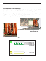
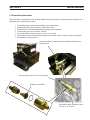
4.4 Anti-freezing Function
Note:
During the purging process, the back pressure regulator setting should not be changed since
the proportional valve is very sensitive to dierential pressure (115 psi /8.0 bar). If the back pres-
sure regulator is changed to a dierent value, the proportional valve might operate in a noisy
manner as the dierential pressure might be greater than 115 psi (8.0 bar). This may happen
initially after starting the pump, resulting in high pressure surge through the proportional valve.
Anti-Freeze air input
SECTION 4 OPERATION
For customers in cold climate areas, purging water out
of the WIC, if the unit is not to be used for long periods
of time, is recommended. To prevent the WIC/hoses/
torch from freezing, the WIC is equipped with an op-
tional anti-freeze mechanism. Compressed air, at 80 psi
(5.5 bar), is introduced through the inlet to ush the cut
water trapped inside the WIC components, hoses and
torch. During purging, the water will come out from the
torch and exhaust valve.
WIC
WATER INJECTION CONTROL
PRESSURE
SENSOR
PROPORTIONAL
VALVE
AIR
SOLENOID
FLOW
SENSOR
ON
OFF
PUMP
POWER
AIR
FREEZE PROTECTION
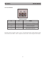
4.4.1 Anti-freezing Procedure
1. Close the water valve.
2. Open the exhaust valve. (refer to Water Injection Control Flow Diagram, next page)
3. On the CNC press the Anti-freeze button shown below.
4. The WIC will open the Air Solenoid.
5. The proportional valve will be turned on slowly up to a xed orice. (See the setup in the station
constant.)
6. Purge will last for 3 minutes while water comes from the torch and the exhaust valve.
7. When timer times out, or Anti-freeze button is pressed again, the air solenoid and the proportional
valve will be turned o.
8. Purge complete.
1. Close the exhaust valve.
2. Open the water valve.
3. On the CNC, press Shield Gas Test, then press Cut Gas Test.
4. Wait until water comes out from the torch.
5. On the CNC, press Cut Gas Test, then press Shield Gas Test. This will stop the water from the torch.
6. Ready for normal operation.
Back to normal operation

29
In Optional Control Mode, to purge the water out of the WIC/hoses/torch, customer needs to set pin B (External
Anti-freeze) to HIGH for at least 3 minutes. Once this signal is removed, purge will stop. However, purge will au-
tomatically stop after 3 minutes even if external anti-freeze is still high.
During purge, customer CNC ignore any ow error or pressure error. When ready to cut again, customer CNC
needs to send a 0.35 gpm command to the WIC, to allow the torch/hose to be lled with water again. Customer
CNC should also ignore ow/pressure errors at this time.
Anti-Freeze function
Cut Shield Test
SECTION 4 OPERATION
Water Injection Control Flow Diagram
Customer Supplied
Components
H2O
PR1
P1/
M1
PT1
PV1/
PWM
FS1
AIR
H2O OUT
IN
IN
(OPTIONAL AIR SUPPLY)
(Valve open
during purge)
EXHAUST
VALVE
WATER
VALVE
FILTER
TO TORCH
CV1
CV2
SOL1
BPR
FILTER

30
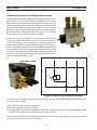
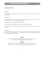
SECTION 4 OPERATION
The Back Pressure Regulator (BPR) manifold assembly (factory set @
40 psi/2.8 bar) consists of a back pressure regulator and two check
valves. This is mounted on or near the Plasma Gas Control, as close to
the torch as possible. The function of the BPR is to maintain the water
pressure to the torch and provide a fast response of the cut water
ow to the torch. Additionally, the BPR prevents the reverse ow of
gas into the WIC or water into the shield gas supply. This is done by
the two check valves inside the manifold assembly.
There are three inputs to the BPR. Cut water from WIC, shield gas and
the air curtain from either the SGC or the CGC. If the system contains
an SGC, the shield gas and air curtain hoses will connect directly to
the input of the BPR. If the system does not contain an SGC, but uses
a CGC, the shield gas output of the CGC should be connected to the
input of the BPR using the short jumper hose included with the BPR
assembly. Two outputs from the BPR are the shield gas or water, and
air curtain to the torch. Depending on the input, the output can be
either water (H2O) or shield gas (SG).
4.5 Back Pressure Regulator (BPR) Manifold Assembly
H2O
SG
A/C
SG/H2O
A/C
CV2CV1
REG
If the BPR setup was disturbed or changed for any reason, customer needs to follow the procedure below to set
pressure to 40 psi (2.8 bar):
(1) Do “Shield Test” for 5-10 seconds, then stop;
(2) Read the water pressure from Vision 50P.
(3) If the water pressure without water owing is not 40 psi (2.8 bar), slowly adjust the screw on the BPR manifold
assembly. Then repeat (1) to (3) until the pressure is 40 psi (2.8 bar).
For Optional Control Mode, instead of doing “Shield Test”, please send a 0.5gpm ow command, and the water
pressure can be read from the 10-pin connector.
ADJUSTMENT SCREW
Figure 4.3 Back Pressure Regulator Schematic
Page is loading ...
Page is loading ...
Page is loading ...
Page is loading ...
Page is loading ...
Page is loading ...
Page is loading ...
Page is loading ...
Page is loading ...
Page is loading ...
Page is loading ...
Page is loading ...
Page is loading ...
Page is loading ...
-
 1
1
-
 2
2
-
 3
3
-
 4
4
-
 5
5
-
 6
6
-
 7
7
-
 8
8
-
 9
9
-
 10
10
-
 11
11
-
 12
12
-
 13
13
-
 14
14
-
 15
15
-
 16
16
-
 17
17
-
 18
18
-
 19
19
-
 20
20
-
 21
21
-
 22
22
-
 23
23
-
 24
24
-
 25
25
-
 26
26
-
 27
27
-
 28
28
-
 29
29
-
 30
30
-
 31
31
-
 32
32
-
 33
33
-
 34
34
-
 35
35
-
 36
36
-
 37
37
-
 38
38
-
 39
39
-
 40
40
-
 41
41
-
 42
42
-
 43
43
-
 44
44


ESAB m3® plasma Water Injection Control User manual
- Category
- Welding System
- Type
- User manual
Ask a question and I''ll find the answer in the document
Finding information in a document is now easier with AI
in other languages
Other documents
-
sks AIR-X-PRESS 8.0 User manual
-
Accu-Tech WIC-024 Datasheet
-
Adcom GFA-7000 User manual
-
 Gas Clip Technologies Single Gas Clip Portable Gas Detector User manual
-
Master MH-40-GFA User manual
-
Adcom GFA-5500 Owner's manual
-
-
ProTemp PT-125V-GFA-A User's Manual & Operating Instructions
-
 SGC Smartuner SG-230 Installation guide
-
Samyung SGC-650 Owner's manual

