Page is loading ...

PN LS10120-001SK-E Rev B
ECN 15-0176
1
EVS-INT50W Internal Amplifier
Installation Instructions
The EVS-INT50W Internal Amplifier can fit
inside the 5820XL-EVS cabinet. It is used to
amplify the audio message for distribution
throughout the facility for the Emergency
Communication System.
Compatibility
The EVS-INT50W is compatible with the Silent
Knight 5820XL-EVS FACP. For programming
and DIP switch settings, refer to Installation
manual for 5820XL-EVS (PN LS10061-001SK-
E).
Board Layout & Mounting
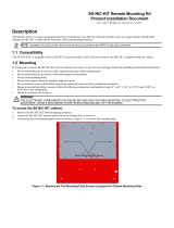
Figure 1: Front View of EVS-INT50W
Mounting the EVS-INT50W
1. Open the cabinet door.
2. Remove AC power and disconnect the
backup batteries from the main control
panel.
3. Align the board with the mounting holes.
Mount the EVS-INT50W inside the FACP
cabinet with the screws provided. See
Figure 2.
Figure 2: EVS-INT50W in FACP Cabinet
4. Secure the board to the enclosure.
Specifications
Standby Current: 52 mA
EVS-INT50W only Alarm Current: @ 25V 275 mA; @
70V 310 mA
Full Alarm load current: @ 25V 2840 mA; @ 70V
2900 mA
SBUS
VBUS
DIP Switch
Power
IN1 / OUT1

EVS-INT50W Internal Amplifier Installation Instructions
LS10120-001SK-E Rev B
ECN 15-0176
2
Wiring to a FACP
See Figure 3 to properly wire the EVS-INT50W
to the FACP.
The Internal Amplifier must be powered by a
NAC programmed as Constant Auxiliary Power.
Refer to the FACP installation manual.
Figure 3: Wiring the EVS-INT50W to the FACP
VBUS Wiring
The VBUS is an analog voice bus that carries
the recorded voice messages from the ECS-
VCM to the EVS-INT50Ws, or the voice
messages generated from a system microphone
to the EVS-INT50W.
The maximum resistance on the VBUS is 20.
Connect the VBUS from the ECS-VCM to the
EVS-INT50Ws as shown in Figure 4.
Figure 4: VBUS Wiring
EVS-INT50W
FACP
EVS-VCM
EVS-INT50W
EVS-INT50W

EVS-INT50W Internal Amplifier Installation Instructions
PN LS10120-001SK-E Rev B
ECN 15-0176
3
Setting the Device Address
Use the on-board DIP switches to select an ID
number for the EVS-INT50W. Refer to
Figure 5
to see how to set the DIP switches for the
desired ID number.
Figure 5: DIP Switch
Once the ID number is set, you must add the
EVS-INT50W to the system through
programming.
Note: EVS-INT50W is powered by a NAC. It will not be
found using JumpStart AutoProgramming.
Speaker Wiring
Each EVS-INT50W supplies one circuit for speaker
connection. The speaker circuit can be supervised
and wired Class B (Style Y) or Class A (Style Z). The
speaker circuit is capable of 50 watts of power at 25
Vrms or 70.7 Vrms.
Wiring Lengths
Note: The above table assumes a uniform distribution of
the speakers, and that a max of 20% voltage drop
on the last speaker is allowed.
Figure 6 illustrates how to wire speakers to the
control panel using Class B (Style Y) supervision.
Table 1: Wire Lengths
Number
Of
Speakers
Total Load Wire Distance in Feet
@ ½
W
@1
W
Vrms Watts
18
AWG
16
AWG
14
AWG
12
AWG
10 5 25Vrms 5W 3900 6200 9860 15680
70Vrms 25000 39700 63200 100520
20 10 25Vrms 10W 2125 3380 5375 8540
70Vrms 15200 24150 38400 61100
30 15 25Vrms 15W 1460 2320 3690 5870
70Vrms 11000 17500 27800 44200
40 20 25Vrms 20W 1100 1750 2780 4420
70Vrms 8500 13510 21500 34175
52 26 25Vrms 26W 760 1200 1920 3050
70Vrms 6100 9700 15400 24520
80 40 25Vrms 40W 550 875 1390 2200
70Vrms 4100 6500 10360 16480
100 50 25Vrms 50W 450 715 1130 1800
70Vrms 3500 5560 8850 14070

EVS-INT50W Internal Amplifier Installation Instructions
PN LS10120-001SK-E Rev B
ECN: 15-0176
4
Figure 6:Class B (Style Y) Speaker Configuration
Figure 7 illustrates how to wire speakers to the
control panel using Class A (Style Z) wiring.
Figure 7: Class A (Style Z) Speaker Configuration
Compatible 520Hz Signaling
Speakers
Table 2: 520 Hz Speakers
Model
Number
Description
SPR Wall High-Fidelity Speaker, Red
SPW Wall High-Fidelity Speaker, White
SPCR Ceiling High-Fidelity Speaker, Red
SPCW Ceiling High-Fidelity Speaker, White
SPSR Wall High-Fidelity Speaker Strobe, Red
SPSRH Wall High-Fidelity Speaker Strobe, High
Candela, Red
SPSW Wall High-Fidelity Speaker Strobe, White
SPSCR Ceiling High-Fidelity Speaker Strobe, Red
SPSCW Ceiling High-Fidelity Speaker Strobe, White
SPSCWH Ceiling High-Fidelity Speaker Strobe, High
Candela, White
SPSCRH Ceiling High-Fidelity Speaker Strobe, High
Candela, Red
SPSCW-
CLR-ALERT
Ceiling High-Fidelity Speaker Strobe, Clear
Lens, ALERT, White
SPSCW-P Ceiling High-Fidelity Speaker Strobe, Plain,
White
SPSCWH-P Ceiling High-Fidelity Speaker Strobe, High
Candela, Plain, White
SPSR-P Wall High-Fidelity Speaker Strobe, Plain,
Red
SPSRH-P Wall High-Fidelity Speaker Strobe, High
Candela, Plain, Red
SPSCWH-P Ceiling High-Fidelity Speaker Strobe, High
Candela, Plain, White
SPSW-
ALERT
Wall High-Fidelity Speaker Strobe, Amber
Lens, ALERT, White
SPSW-
CLR-ALERT
Wall High-Fidelity Speaker Strobe, Clear
Lens, ALERT, White
SPSW-P Wall High-Fidelity Speaker Strobe, Plain,
Red
SPSWH Wall High-Fidelity Speaker Strobe, High
Candela, White
SPSWH-P Wall High-Fidelity Speaker Strobe, High
Candela, Plain White
Table 2: 520 Hz Speakers
Model
Number
Description
/