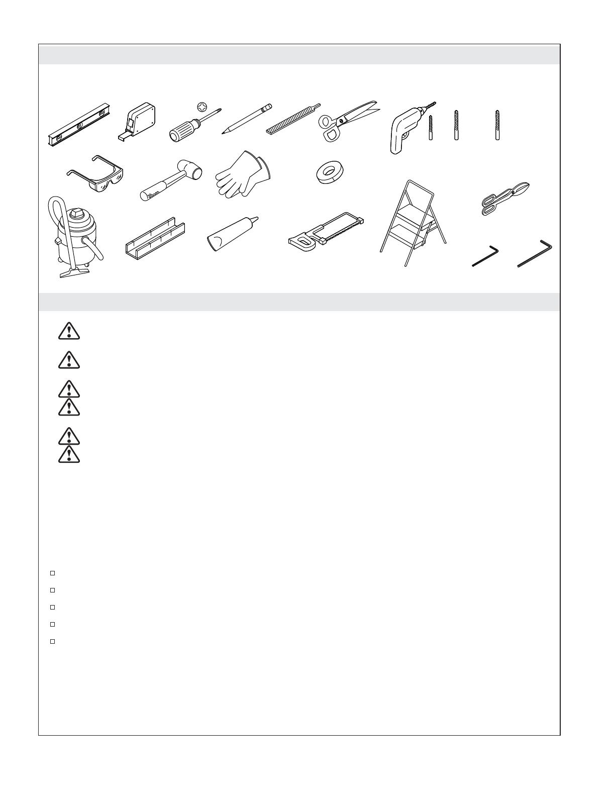
Kohler K-707601-8D3-BL Installation guide

Type
Installation guide
Installation Guide
Sliding Shower and Bath Doors
Français, page “Français-1”
Español, página “Español-1”
1380408-2-B
Tools and Materials
Before You Begin
WARNING: Risk of serious injury. Damage before installation can result in glass shattering.
Inspect the glass and all parts for damage before installation.
WARNING: Risk of serious injury. Improper installation can result in glass shattering. Follow all
installation instructions.
WARNING: Risk of serious injury. Do not cut tempered glass. Tempered glass will shatter if cut.
WARNING: Risk of serious injury. Shower door and side panels can shatter. Regularly inspect the
glass and all parts for damage, missing or loose parts.
WARNING: Risk of serious injury. Always wear safety glasses while cutting and drilling.
CAUTION: Risk of personal injury. Tempered glass should not contact hard surfaces or it may
shatter. Do not touch the edge of the tempered glass panel with tools or any hard objects.
IMPORTANT! Leave this manual for the end user. Read these instructions before installing or using this
product.
IMPORTANT! This door is designed to accommodate walls that are less than 3/8 (10 mm) out of plumb.
Verify the area the door will be attached to is within 3/8 (10 mm) of plumb. The door may not function
properly if the wall is more than 3/8 (10 mm) out of plumb.
IMPORTANT! Do not remove the corner protectors from the door panels until after they are installed.
Cover the drain with tape to avoid loss of small parts.
Identify all parts prior to installation.
Follow the silicone sealant manufacturer’s instructions for application and curing time.
Two people should perform this installation.
To watch this installation video online, visit us.kohler.com and search for your product number.
32-Teeth
Per Inch Blade
100% Silicone
SealantMiter Box
Masking Tape
Tin Snips
Step Stool
1/8" 1/4" Masonry
Bit for Tile
1/8"
1/4"
3/32"
1380408-2-B 2 Kohler Co.
Parts Identification
Headers
Cleat
Right
Bumper
Cleat
Left
Bumper
Seal
Wall
Jamb
Seal
Wall
Jamb
Threshold
Threshold
Seal
Centerguide
Clip
Header
Connectors
Header
Connectors
Bracket
Bumper
Screw
Anchor
Bracket
Bumper
Screw
Anchor
Screw
#6-20" x 3/8"
Handle
Kit
Roller
Kit
Kohler Co. 3 1380408-2-B
1. Confirm Ledge and Wall Compatibility
IMPORTANT! For proper door alignment and operation, confirm that the shower base/bath ledge and
walls meet the following requirements. Do not install the door if these requirements are not met.
There must be at least 2-1/2 (64 mm) of flat surface on the shower base/bath ledge and walls.
Walls must be within 3/8 (10 mm) of plumb.
The shower base/bath ledge must be level between the walls.
The radius of the shower base/bath ledge where it meets the wall must be 1/4 (6 mm) or less.
1/4" (6 mm)
Max Radius
2-1/2"
(64 mm)
Min
2-1/2"
(64 mm)
Min
1380408-2-B 4 Kohler Co.
2. Measure and Cut the Threshold
WARNING: Risk of serious injury. Always wear safety glasses while cutting and drilling.
Cover the drain with tape to avoid the loss of small parts.
Use a drop cloth to protect the shower surface.
Measure distance A between the shower walls and mark it on the threshold.
Measure 1/2 (13 mm) from A and make a second mark on the threshold as shown.
Cut the threshold at the second mark and file any rough edges.
Cut
here.
A
A
A
Threshold
1/2"
(13 mm)
1/2"
(13 mm)
Kohler Co. 5 1380408-2-B
3. Install the Centerguide
Measure the center of the threshold. Mark the centerline near the groove on the inside surface of the
threshold.
IMPORTANT! Drill through the inside surface only.
Drill a 1/8 hole at the centerline on the groove of the inside surface of the threshold.
Install the centerguide clip to the threshold with the supplied #6 x 3/8 screw.
Press the centerguide over the clip. Make sure the centerguide is completely installed with the tabs
snapped under the bottom of the threshold.
Inside
Surface
Tabs
Groove
1/8"
(3 mm)
Hole
1380408-2-B 6 Kohler Co.
4. Install the Bumpers to the Threshold
NOTE: There is a left side and right side bumper. The cleats are identical.
Install a cleat into each end of the threshold so that they point in the same direction as the
centerguide.
Press the left and right bumpers onto the cleats as shown.
Left
Bumper
Right
Bumper
Cleat
Cleat
Kohler Co. 7 1380408-2-B
5. Install the Threshold Seal
IMPORTANT! The seal must be installed with at least 1/2 (13 mm) extending beyond each end of the
threshold. The seal will be cut to fit after the threshold has been installed.
Press the seal into the channel in the threshold, leaving approximately 1/2 (13 mm) extending
beyond the end of the threshold.
1/2" (13 mm)
Seal
1/8"
1380408-2-B 8 Kohler Co.
6. Position the Threshold
NOTICE: The threshold must sit on a flat surface.
Thoroughly clean the shower base/bath ledge before proceeding.
If needed, file the ends of the threshold to match the corner radius of the shower wall.
Set the threshold assembly on the flat surface of the shower base/bath ledge, as close to the outside
edge as possible.
Align the threshold even distance along the ledge.
Mark the threshold location, then remove the threshold.
Remove the film from the adhesive on the bottom of the centerguide.
Install the threshold on the marks and press firmly on the centerguide to bond the adhesive.
Kohler Co. 9 1380408-2-B
7. Complete the Threshold
Use masking tape to temporarily secure the threshold in place until the wall jambs are installed.
Press the bumpers against the walls.
Use a scissors to trim the seal at each end of the threshold so that it mates with the notch in the
bumper.
Notch
Seal
Seal
1380408-2-B 10 Kohler Co.
8. Assemble and Position the Wall Jambs
NOTE: The flexible fin of the seal is on the inside of the wall jambs.
NOTE: The wall jambs are longer than the seals.
Starting at the top, press a seal onto each wall jamb so that there is a left-side assembly and a
right-side assembly as shown.
Position the wall jamb assemblies over the threshold so the flexible fin is on the inside of shower. If
needed, snip the corners of the metal to fit the corner radius of the shower wall.
Use a level to plumb the wall jambs and mark the locations on the wall.
Use masking tape to temporarily secure the upper part of the wall jambs in place. Do not secure
with the adhesive on the back of the seal at this time.
Right Left
Fin
Fin
Kohler Co. 11 1380408-2-B
9. Prepare the Wall Bracket Holes
IMPORTANT! Hole locations for the wall brackets are critical. Make sure the holes are properly marked
and drilled straight into the wall.
Make sure the top of the wall jamb is secured in place with masking tape.
Place the drill template over the wall jamb, pointing into the shower as shown.
Verify that the template is fully seated over the wall jamb, flat against the wall, and level.
Mark the hole locations.
Remove the template and drill 1/4 holes straight into the wall at the marked locations. Make sure
the drill is not at an angle when drilling.
Install the provided wall anchors. Make sure the anchors are fully seated into the wall.
Repeat for the second wall jamb.
1/4"
1380408-2-B 12 Kohler Co.
10. Install the Wall Brackets
Thoroughly clean the wall and shower area before proceeding.
Secure each bracket to the wall using two #8-18 x 1-1/2 screws.
Verify that the bracket is level. Loosen the screws and adjust the bracket position if needed.
Repeat for the second bracket.
Kohler Co. 13 1380408-2-B
11. Measure and Cut the Headers
IMPORTANT! Confirm your measurements before cutting. Do not cut the headers too short.
Measure distance “B” between the finished shower walls and mark it on each of the two headers.
Using a hand saw, position the blade just inside the marked line. Cut each header just inside the
marked line.
File any rough edges and clean debris from the roller tracks.
B
Header
B
1380408-2-B 14 Kohler Co.
12. Install the Connectors to the Headers
Locate the notches along the inside tracks of the headers.
Mark the locations with pieces of tape on the outside of the headers. This will help with door panel
installation later.
NOTE: Inner and outer headers are identical.
Push a header connector into the end of each header as shown. The hex screw head should be
visible.
Position each connector approximately 2 (51 mm) from the ends of the headers so they are clear of
the brackets during header installation.
Setscrew
Notches
Tape
2"
(51 mm)
Kohler Co. 15 1380408-2-B
13. Position the Inside Header
IMPORTANT! Install only the inside header at this time.
NOTICE: The two headers are identical.
To ease installation of the header, remove the temporarily positioned wall jambs.
With the flat face of the header facing the inside of the shower, tilt the header as shown and lower it
on to both brackets at the same time.
Rotate the header onto both brackets at the same time to a vertical position.
NOTE: The header will be slightly loose. It will be secured in the next section.
Inside
Header
1380408-2-B 16 Kohler Co.
14. Secure the Inside Header to the Bracket
IMPORTANT! The inside header is secured to the brackets in this step so that the door panel may be
hung.
Press the header against the bracket, and slide the header connectors all the way to the wall at each
end of the header.
NOTE: If the header connector does not slide over the bracket, either the screw must be loosened, the
header is not properly installed on the bracket, or the bracket is tilted away from the wall. Make any
adjustments as necessary.
Secure the header by tightening each header connector screw with a 1/8 hex wrench.
1/8"
Press against
the bracket.
Kohler Co. 17 1380408-2-B
15. Assemble the Inside Panel Rollers
NOTICE: There is a triangle shape molded on one of the flats of the roller.
Orient the door panel so that the handle holes are on the showerhead side and the label faces the
outside of the shower.
Position the roller and gasket on the opposite side of the panel as the label as shown, and insert the
roller cam into the hole.
Orient the roller so that the triangle is pointing up. This sets the door at its lowest position, making
adjustments easier.
Firmly handtighten the roller to the glass with the gasket and bolt.
Using the supplied wrench, securely tighten the bolt at least 3/4 turn past hand-tight. The gasket
may flex as the bolt is tightened.
Repeat these steps for the second roller.
Triangle Up
Gasket
Cam
Wrench
Bolt
Bolt
Gasket
1380408-2-B 18 Kohler Co.
16. Install the Inside Panel
CAUTION: Risk of product damage: Once installed, do not move the panel close to the wall because the
top bumpers are not installed at this time.
NOTE: The corner protectors should still be installed on the panel at this time.
NOTE: The rollers face the inside of the shower and the label faces the outside of the shower.
With help, from outside the shower, lift the panel and place the bottom into the inside channel in
the centerguide.
Lift the panel just enough to place a roller into one notch on the header. Then slide the panel over
so the second roller is aligned with the other notch in the header.
Verify that the bottom of the door panel is still in the inside channel of the centerguide.
Kohler Co. 19 1380408-2-B
17. Assemble the Outside Panel Rollers
NOTICE: There is a triangle shape molded on one of the flats of the roller.
Orient the door panel so that the handle holes are on the opposite side as the showerhead and the
label faces the outside of the shower.
Position the roller and gasket on the same side of the panel as the label as shown, and insert the
roller cam into the hole.
Orient the roller so that the triangle is pointing up. This sets the door at its lowest position, making
adjustments easier.
Firmly handtighten the roller to the glass with the gasket and bolt.
Using the supplied wrench, securely tighten the bolt at least 3/4 turn past hand-tight. The gasket
may flex as the bolt is tightened.
Repeat these steps for the second roller.
Triangle Up
Gasket
Wrench
Bolt
Bolt
Gasket
1380408-2-B 20 Kohler Co.
  • Page 1 1
  • Page 2 2
  • Page 3 3
  • Page 4 4
  • Page 5 5
  • Page 6 6
  • Page 7 7
  • Page 8 8
  • Page 9 9
  • Page 10 10
  • Page 11 11
  • Page 12 12
  • Page 13 13
  • Page 14 14
  • Page 15 15
  • Page 16 16
  • Page 17 17
  • Page 18 18
  • Page 19 19
  • Page 20 20
  • Page 21 21
  • Page 22 22
  • Page 23 23
  • Page 24 24
  • Page 25 25
  • Page 26 26
  • Page 27 27
  • Page 28 28
  • Page 29 29
  • Page 30 30
  • Page 31 31
  • Page 32 32
  • Page 33 33
  • Page 34 34
  • Page 35 35
  • Page 36 36
  • Page 37 37
  • Page 38 38
  • Page 39 39
  • Page 40 40
  • Page 41 41
  • Page 42 42
  • Page 43 43
  • Page 44 44
  • Page 45 45
  • Page 46 46
  • Page 47 47
  • Page 48 48
  • Page 49 49
  • Page 50 50
  • Page 51 51
  • Page 52 52
  • Page 53 53
  • Page 54 54
  • Page 55 55
  • Page 56 56
  • Page 57 57
  • Page 58 58
  • Page 59 59
  • Page 60 60
  • Page 61 61
  • Page 62 62
  • Page 63 63
  • Page 64 64
  • Page 65 65
  • Page 66 66
  • Page 67 67
  • Page 68 68
  • Page 69 69
  • Page 70 70
  • Page 71 71
  • Page 72 72
  • Page 73 73
  • Page 74 74
  • Page 75 75
  • Page 76 76
  • Page 77 77
  • Page 78 78
  • Page 79 79
  • Page 80 80
  • Page 81 81
  • Page 82 82
  • Page 83 83
  • Page 84 84
  • Page 85 85
  • Page 86 86
  • Page 87 87
  • Page 88 88
  • Page 89 89
  • Page 90 90
  • Page 91 91
  • Page 92 92
  • Page 93 93
  • Page 94 94
  • Page 95 95
  • Page 96 96

Kohler K-707601-8D3-BL Installation guide

Type
Installation guide

Ask a question and I''ll find the answer in the document

Finding information in a document is now easier with AI