Page is loading ...

Phone: +1 (214) 421-7366
Fax: +1 (214) 565-0976
Toll Free: +1 (800) 527-2100
Website: www.apwwyott.com
E-mail: [email protected]
INSTALLATION
AND
OPERATING
INSTRUCTIONS
INTENDED FOR OTHER THAN HOUSEHOLD USE
Model: M Series
Model: AT / BT Series
RETAIN THIS MANUAL FOR FUTURE REFERENCE
UNIT MUST BE KEPT CLEAR OF COMBUSTIBLES AT ALL TIMES
P/N 57212 9/06
1
DIAGONAL CONTACT CONVEYOR TOASTER
HORIZONTAL RADIANT CONVEYOR TOASTER
APW WYOTT
729 Third Avenue
Dallas, TX 75226
This equipment has been engineered to provide you with year-round dependable service when used
according to the instructions in this manual and standard commercial kitchen practices.
WARNING: Improper installation, adjustment, alteration, service or maintenance can
cause property damage, injury or death. Read the Installation, Operating and
Maintenance Instructions thoroughly before installing or servicing this equipment.
!!
R

TABLE OF CONTENTS
GENERAL INFORMATION AND TROUBLESHOOTING 2
M SERIES - DIAGONAL CONTACT CONVEYOR TOASTERS 3-9
Electrical Specifications 3
Installation 3
Location 6
Operating Instructions 6
Field Adjustments & Cleaning 7
Troubleshooting Guide 9
AT SERIES - HORIZONTAL RADIANT CONVEYOR TOASTERS 10-13
Electrical Specifications 10
Installation 11
Convertible Instructions 12
Operating Instructions 13
BT-15 SERIES 14-16
Electrical Specifications 14
Installation 14
Operating Instructions 15
WARRANTY IN FORMATION 19
GENERAL INFORMATION
General Installation:
1. Always clean equipment thoroughly before first use. (See general cleaning instructions).
2. Check rating label for your model designation & electrical rating.
3. Locate equipment on level counter and plug into a grounded outlet so that the plug is accessible.
(See individual description for electrical loads).
4. On units bearing the CE marking, the appliance must be connected by an earthing cable to all other
units in the complete installation and then to an independent earth connection.
GENERAL TROUBLESHOOTING
Always ask & check:
1. Is the unit plugged in?
2. Check circuit breaker.
3. Is power switch on and pilot light glowing?
4. Check rating label. Are you operating unit on proper voltage?
5. If the supply cord is damaged it should be replaced by an identical supply cord.
If the above checks out and you still have problems, call an APW Wyott authorized service agency.
2
!
!
WARNING: In Europe, appliance must be connected by an earthing cable to all other units
in the complete installation and thence to an independent earth connection in compliance
with EN 60335-1 and/or local codes
!
!
WARNING: An earthing cable must connect the appliance to all other units in the complete
installation and from there to an independent earth connection.

Model Stock Dimensions* Electrical Productivity Weight
Number Number Halves/Hour Net/Ship
83501 120V-1600W-13.3A Up to 1600
M-83 83502 20"H x 24 5/8"W x 12"D 208V-1600W-7.7A “ “ 83/93 Ibs
83504 50.8 cm x 62.6 cm x 30.5 cm 230V-1470W-6.4A-50Hz “ “ 37.7/42.2 kg
240V-1600W-6.7A
84578 120V-1600W-13.3A Up to 1600
M-830 84579 20"H x 24 5/8''W x 12"D 208V-1600W-7.7A “ “ 83/93 Ibs
84590 50.8 cm x 62.6 cm x 30.5 cm 230V-1470W-6.4A-50Hz “ “ 37.7/42.2 kg
240V-1600W-6.7A
M952AA001 120V-1800W-15A
M-95-2 M952CA001 30 1/2"H x 21 1/2"W x 17 1/2"D 208V-2780W-13.4A 681bs.
M952EA001 77.5 cm x 54.7 cm x 44.5 cm 230V-2550W-11.1 A-50Hz 30.9 kg
240V-2780W-11.6A
M953AA001 120V-1800W-15A
M-95-3 M953CA001 30 1/2"H x 24 1/2"W x 17 1/2"D 208V-2780W-13.4A 77lbs.
M953EA001 77.5 cm x 62.3 cm x 44.5 cm 230V-2550W, 11.1 A-50Hz 35 kg
240V-2780W-11.6A
*With Superfeeder: M-83 & M-83D - add 11” (28cm) to height, 4 1/2” (11.5cm) to depth.
M-83, M-83-D & M-91 & M-95
SPECIFICATIONS:
PLEASE READ PAGE 2 - “GENERAL INFORMATION”, BEFORE YOU CONTINUE.
Electrical Information - All Models
Each unit is equipped with a 4 foot (122cm), 3 wire grounded power supply cord which terminates with a 3
prong plug. The 120V units have a NEMA 5-15P plug. The 208/240V units have a NEMA 6-20 plug.
NOTE: Units rated 120V for installation in Canada have a NEMA 5-20P plug.
INSTALLATION
1. UNPACK UNIT
a) Remove unit from shipping carton, unwrap loose parts and remove any packing tape,
plastic wrap and nylon tie-down.
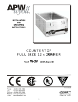
b) Refer to the illustrations below and account for the following parts:
Part M-83 M83-D M-91 M-95
Legs (Item 1) wrapped, internal package wrapped, internal package wrapped, internal package wrapped, internal package
Butter Roller (Item 2) plastic wrapped, shipped in place - plastic wrapped, shipped in place -
Butter Pan (Item 3) plastic wrapped, shipped in place - plastic wrapped, shipped in place -
Conveyor (Item 5) boxed, external package. boxed, external package strapped in place with nylon tie -
Bun Chute Feeder (Item 7) shipped in box with Conveyor shipped in box with Conveyor wrapped, internal package wrapped, internal package
Instruction Manual wrapped, internal package wrapped, internal package wrapped, internal package wrapped, internal package
Teflon Sheet Kit (optional) wrapped, internal , package wrapped, internal package wrapped, internal package -
NOTE: Prior to initial start-up, all removable parts and the grill surface should be cleaned with warm, soapy
water to remove manufacturing oils, then rinsed and dried thoroughly. Apply oil to the conveyor chain after
washing. Also the grill surface should be seasoned with a light coating of oil (fry oil works well) and pre-
heated for 15 - 20 minutes.
3

4
2. ASSEMBLY (REFER TO ILLUSTRATIONS ABOVE)
a) Lay the toaster on its side and install the four Adjustable Legs (Item 1) in threaded holes in
base. Tighten legs with crescent wrench. The unit may be leveled by unscrewing the lower
insert of each leg. Precise leveling is not required for proper operation of the toaster. Set the
toaster upright.
CAUTION: DO NOT OPERATE THE TOASTER WITHOUT THE LEGS INSTALLED.
3. CONVEYOR INSTALLATION
M-83 Only:
Remove Butter Roller (Item 2) by pushing shaft to the left to disengage. Remove Butter Pan (Item 3)
by lifting the pan up and off the supporting pins.
M-83/M-83D:
a) Remove Top Front Panel (Item 4A) by gripping the two black knobs while lifting up and
slightly back. The Bottom Front Panel (Item 4B) can then be removed by grasping the top
edge with one hand and pulling straight back. Hold the bottom with the other hand and lift up
and toward the front; then slide panel down and out underneath the Butter Roller bushings.
b) Grasp Conveyor (Item 5) by the handles. Lower conveyor knobs into right and left Hangar
Brackets (Item 6A/B). Gently push forward to engage gears.
CAUTION: THE CONVEYOR IS HEAVY. DO NOT DROP INTO POSITION. DROPPING
MAY CAUSE DAMAGE TO GEARS.
c) Replace Bottom Front Panel (Item 4B), Top Front Panel (Item 4A), Butter Pan (Item :3) and
Butter Roller (Item 2)
M-91 :
a) The Conveyor (Item 5) is shipped in place and strapped down with nylon tie. To remove
nylon tie, follow steps b, c and d. .
b) Remove Butter Roller (Item 2) by pushing shaft to the right to disengage. Remove Butter
Pan (Item 3) by sliding toward the front of the unit, underneath the Butter Roller Bushings.
c) Remove Front Panel (Item 4) by gripping the top edge with one hand and the bottom edge
with the other hand. Lift up to disengage slots in panel from retaining rods, then move
forward and slide down and out underneath the Butter Roller Bushings.
d) Cut and remove the nylon tie securing the conveyor. (Note: To remove for cleaning, see
"Disassembly" Instructions.)
e) Replace Front Panel (Item 4), Butter Pan (Item 3) and Butter Roller (Item 2).
M-95
a) The Conveyor (Item 5) is shipped in place and strapped down with nylon tie. To remove
nylon tie, follow steps b, c, and d.
b) Remove Butter Roller (Item 2) by lifting left side of butter roller shaft. Remove Butter Pan by
sliding toward the front of the unit, underneath the butter roller bushings.
1
1
1
2
2
2
3
3
3
4A
4A
4B
5
5
5
6B
6A

c) Remove Top Front Panel (Item 4A) by gripping rear edge and lifting up. The Bottom Front
Panel (Item 4B) can then be removed by holding the top edge with one hand and the bottom
edge with the other hand, then lifting panel up.
d) Cut and remove the nylon tie securing the conveyor. (Note: to remove for cleaning, see
"Disassembly" instructions.)
e) Replace Bottom and Top Front Panels (Items 4A & 4B), Butter Pan (Item 3) and Butter Roller
(Item 2).
4. BUN CHUTE/FEEDER/SUPER FEEDER INSTALLATION
M-83/M-83D: Install Bun Chute/Feeder (Item 7) by fitting slots on each side onto back panel studs
located at top rear of unit. .
M-91: Install Feeder/Super Feeder (Item 7) by sliding feeder support "legs" into channels
located at top rear of unit.
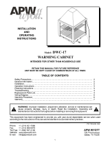
5. INSTALLATION OF OPTIONAL TEFLON SHEET FOR DRY OPERATION AND/OR INCREASED
EASE OF CLEANING
NOTE: Apply light coating of oil to grill surface prior to installation of Teflon sheet.
M-83 & M-91
a) Lay Teflon Sheet on flat surface.
Measure approximately 2" from end of
sheet. Notch corners as needed. Fold
under 2" long flap. Crease Teflon
Sheet at 2" fold.
b) Remove Super Feeder (bun chute).
From rear of Teflon Sheet retainer
bracket, slip 2" fold of Teflon Sheet
under bracket. Bring balance of sheet
forward and smooth sheet down
against grill plate.
c) Reinstall Super Feeder bun chute.
M-95
a) Slide one' end of teflon sheet beneath
conveyor to bottom of grill plate.
b) Place other end of teflon sheet over
top edge of grill plate.
c) Install teflon sheet retainer over teflon
sheet and grill plate.
Teflon Sheet
Teflon Sheet
Retainer Bracket
Grill
Plate
M-83 & M-91
M-83 Teflon Sheet Kit P/N 87449
M-91 Teflon Sheet Kit P/N 83764
M-95
M-95-2 Teflon Sheet Kit P/N 84177
M-91-3 Teflon Sheet Kit P/N 84176
5

6
LOCATION
.
1. Place the toaster on a flat surface and in such a way that the unit's vents are not blocked. Air must
circulate under and through the vents provided on the base, right side (M-83, M83D, & M-95), left
side (M-91) and rear of the unit.
2. Locate the unit near a wall receptacle of the proper configuration. DO NOT USE AN EXTENSION
CORD. Plug the power supply cord into an outlet (receptacle) of the voltage specified on the unit's
rating plate. Outlets must be properly grounded.
M-83 & M-91 OPERATING INSTRUCTIONS
A. PREPARATION
1. Warm-up Time: Turn the control knob to 400°F (number 8) or 450°F (number 9) using
optional Teflon Sheet. Wait 15-25 minutes or until the pilot light cycles on and off twice.
2. Use of Oil: Any high-quality oil may be used in the Bun Grill Toaster. While health concerns
have led to the decreased use of tropical cooking oils, coconut oil does caramelize when
toasted to give the product an appetizing golden color. It also helps the product to reach and
maintain the optimum serving temperature. Whereas some cooking oils tend to gum up,
those designed for use in toasters will work throughout the day without the need to stop and
clean the grill.
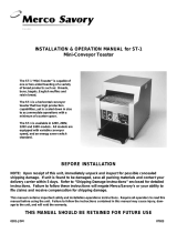
Pilot Light
Motor Switch
Temperature
Control
Main Switch
Motor Switch
Pilot Light
Temperature
Control
Main Switch
M-83 & M-95 Toaster
M-91 Toaster
B. CONTROL PANEL
The face of the panel has two (2) Iighted rocker switches and a temperature control:
1. Main S witch - main power On/off.
2. Motor Switch - On/off switch turns both butter roller and conveyor on and off.
3. Temperature Control - Controls the temperature of the grill. The pilot light will stay on until
the grill temperature has been attained and will then turn off. Allow .the pilot light to cycle
twice so the unit is at stabilized temperature for toasting buns.
NOTE: During slow periods to conserve energy and prolong motor life, you may turn
temperature control down to 150°F (66°C) and turn off motor switch.
4. Pilot Light - Glows when grill is on.

7
C. PRODUCTION
To Grill Buns - the following is the basic
procedure to operate the bun toaster.
Fig. 1. Heat toaster oil to melting point and fill
the butter roller tray 2/3 full.
Fig. 2. Turn "Main" power switch to "on." Turn
motor switch "on"; the butter roller and
conveyor will start. The oil should spread
evenly over the butter roller cylinder.
Fig. 3. Now... hold a bun half in the palm of
the hand and in one motion (1) slap the sliced
surface of the bun on the butter roller, and (2)
drop the bun, sliced surface toward the grill,
into the top of the unit. The bun half will drop
out in the front at the bottom of the unit.
Fig. 4. The resulting toasted bun should be
(a) hot to the touch, (b) soft and fresh and (c)
a golden brown color over the entire surface.
If the .toast is slightly warm, dry and pale
colored, this indicates that the oil has been
improperly applied. Try several buns for
practice.
PRODUCT PATH
PRODUCT INTERIOR TEMPERATURE: The interior temperature of the bun will be in the range of
150°F - 160°F (66°C - 71°C) depending upon the amount of oil and grill temperature setting of the
control.
Fig. 5. If you want a lighter or darker color to the bun, decrease or increase the temperature setting.
Fig. 6. NOTE: Should you change the setting, please allow two (2) cycles for the grill plate to adjust
to the new setting. Once you have settled on a bun color, note the setting and keep it there. To turn
unit off, just use main switch.
FIELD ADJUSTMENTS & CLEANING
A. DISASSEMBLY (REFER TO ILLUSTRATIONS ON PAGE 2.)
1. Turn main power switch "off."- Remove power supply plug from wall receptacle.
2. Remove Butter Roller (Item 2).
M-3 & M-83D Only: Push Butter Roller shaft to the left to disengage the notched end of the
shaft from the drive motor and remove. To facilitate cleaning, the shaft assembly may be
separated from the Butter Roller cylinder. Hold cylinder securely with one hand and slide the
shaft out with the other hand.

8
M-91: Push Butter Roller shaft to the right to disengage the notched end of the shaft from
the drive motor and remove. To facilitate cleaning, the shaft assembly may be separated
from the Butter Roller cylinder. Hold cylinder securely with one hand and slide the shaft
out with the other hand.
M-95: Lift left side of butter roller shaft out of "cradle" and remove. To facilitate cleaning, the
shaft assembly may be separated from the Butter Roller cylinder. Hold cylinder securely
with one hand and slide the shaft out with the other hand.
3. Remove Butter Pan (Item 3).
M-3: Lift the Butter Pan up and off the supporting pins.
M-91 & M-95: Slide Butter Pan toward the front of the unit and beneath the Butter Roller
bushings.
4. Remove Front Panel(s) (Item 4).
M-3: Remove the Top Front Panel (Item 4A) first by gripping the "two black knobs and lifting
up and slightly back. The Bottom Front Panel (Item 4B)can then be removed by holding the
top edge with one hand and pulling straight back. Next, hold the bottom edge with the other
hand and lift up and toward the front; then slide panel down and out between the Butter
Roller bushings.
M-93: To remove the Front Panel (Item 4) grasp the top edge with one hand and the bottom
edge with the other hand. Lift up to disengage slots in panel, then move forward and slide
down and out underneath the Butter Roller bushings: "
M-95: T0 remove the Top Front Panel (Item 4A) grip rear edge and lift up. The Bottom Front
Panel (Item 4B) can then be removed by holding the top e(jge with one hand and the bottom
edge with the other hand, then lifting panel up.
5. Remove Conveyor (Item 5).
Grasp Conveyor by the handles on each side and pull toward the front of the unit to
disengage gears. Gear engagement may be tight; if so, push the conveyor chain weights
slightly to rotate conveyor. Then lift Conveyor up and off the left and right Hangar Brackets.
CAUTION: THE CONVEYOR IS HEAVY. HOLD TIGHTLY.
6. Remove Bun Chute/Feeder/Super Feeder (Item 7). (M-83 & M-91 Only.)
M-83: Lift Bun Chute or Feeder up and off the back panel studs located at top rear of unit on
left and right sides.
M-91: Remove the Feeder/Super Feeder by gripping the sides and lifting up so that" support
"legs" slide out of the channels at rear of unit. "
7. M-83 Only - To remove the Bottom Rear Back Panel (not shown in illustration), face the rear
of the unit, grip the two black knobs, and lift up and off the left and right support pins.
8. M-91 Only - Remove lower Front Bun Slide (Item 8) by lifting up and off the support studs
and pulling forward.
B. FIELD ADJUSTMENT OF GRILL PRESSURE:
Bun grilling is a function of THREE FACTORS: Speed, Temperature and Pressure. If speed and
temperature have been adjusted (see page 4), and optimum browning has not been achieved,
adjust the conveyor hanging brackets (Item 6A1B). loosen left and right brackets. Move them
equally toward the grill plate in 1/8" (.32 cm) increments and re-tighten screws. Adjust gear
engagement as needed with hanger plate bolts and lock nuts. CAUTION: Make sure grill plate is
cool.
C. CLEANING:
1. All of the parts removed from the unit may be placed in a dishwasher or sink for washing with
your usual detergent and hot water. Use a grill screen or plastic abrasive pad (Scotch Brite
pads are recommended) to remove stubborn baked-on oil from grill plate surface. DO NOT
use stee1 wool. Rinse thoroughly and dry. Oil chains after washing (apply toaster oil).
2. Grill Plate-Scour grill plate completely, rinse and dry thoroughly. Then coat with a light film of
toaster oil. (For baked-on oil use grill screen or Scotch-Brite pad).
3. Reassemble.

9
a. Set Thermostat at 4000 or number 8 and allow a full
20 minutes for warm-up.
b. Coconut oil is the recommended oil. Use of other
oils will prove to be unsatisfactory.
c. Sun surface should have even application of oil.
d. Use fresher bread. Get better cutting from baker.
a. Improper application of oil - brush bun over butter
roll so as to provide bun surface with even coating
of oil.
b. Use fresher bread. Get better cutting from baker.
c. Adjust conveyor hanging brackets.
a. Review Operation Information, Paragraph A, "Use of
Oil"
b. Clean grill surface. Use Chore-Girl Pads to cut
through residue. Daily cleaning will prevent residue
build-up
c. Set temperature to 4100 or number 8 and, perhaps,
use day-old buns or try another bun source.
d. Use sandpaper to roughen the surface of the
weight.
e. Defrost buns.
f. Use Teflon sheet.
a. Check fuse of breaker panel.
b. Check plug.
c. Check the relay output (M-83),
d. Check that switch is on and operative.
e. Check and reset.
a. Check power cord connection in control panel.
b. Check control.
c. Replace thermostat.
d. Replace element.
a. Check switch for loose or broken connections.
b. Replace switch.
c. Replace motors.
a. Realign butter roll shaft to engage with drive.
b. Reverse butter roll and shaft assembly notched end
toward motor drive.
a. Remove conveyor and re-install to make sure drive
gears engaged properly.
b. Check weights for clearance between each one.
c. Check conveyor linkage for bent links.
a. Check circuit switch to conveyor motor for loose or
broken connection.
b. Replace motor.
a. Wrong temperature setting.
b. Wrong oil is used.
c. Improper application of oil.
d. Excessive cupping of bread
surface.
a. Only part of bun surface is
toasted - other part is pale in
color and dry.
b. Excessive cupping of bread
surface.
c. Not enough pressure.
a. Wrong oil is used.
b. Grill surface has baked-on oil
residue.
c. Doughy buns or excess sugar
and moisture plus overheated
grill may cause sticking.
d. Bun weights on conveyor chain
assembly are too slick and
slide off the bun.
e. Buns not defrosted
f. For c, d, and e above.
a. No power at wall receptacle.
b. Plug disconnected.
c. Relay (M-83).
d. Main Switch.
e. Circuit Breaker.
......and conveyor and butter roller
are OKAY
a. Loose power cord connections.
b. Loose control connections.
c. Faulty thermostat
d. Burnt out element.
......and grill OKAY
a. Loose connections to switch.
b. Switch burned out.
c. Motors defective.
......and butter roller motor OKAY
a. Notched end of butter roll shaft
not engaged with motor drive.
b. -or wrong end of shaft inserted
in spring loaded socket.
......and conveyor motor OKAY
......and butter roller OKAY
a. Drive gears not engaged.
b. Bun weights are binding.
c. Linkage is binding - and
conveyor drive motor won't turn.
a. Loose connection between
switch and conveyor motor.
b. Conveyor motor burnt out.
Buns won’t toast....
Buns toast unevenly. . . .
Buns stick to grill. . . . . .
Unit Dead - No power. .
Grill won't heat. . . . . . . .
Conveyor and Butter Roller
Inoperative. . . . . .
Butter Roller won't turn .
Conveyor won't move. . .
Conveyor won't move. . .
PROBLEM CAUSE SOLUTION
CONTACT TOASTER TROUBLESHOOTING GUIDE

AT-10, AT-30, AT-10BT, AT-5, AT-200
SPECIFICATIONS
PLEASE READ PAGE 2 - "GENERAL INFORMATION," BEFORE YOU CONTINUE.
Electrical Information - Models AT-10 & AT-30:
Each unit is equipped with a 4 foot (122 cm), 3 wire grounded power cord which terminates with a standard 3
prong plug. The 120V units have a 5-15P plug. The 208/240V units have a 6-20P plug.
1 ½" (3.8 cm) Product Opening:
14"H x 18 5/16"W x 21 5/8"D
(35.6 cm x 46.6 cm x 55 cm)
3" (7.6 cm) Product Opening:
15 1/2"H x 18 5/6"W x 21 5/8"D
(39.4 cm x 46.6 cm x 55 cm)
1 1/2" (3.8 cm) Product Opening:
208V-3340W-16.1 amps
230V-3070W-13.4 amps-50 Hz
240V-3340W-14.0 amps
3" (7.6 cm) Product Opening:
208V-3340W-16.1 amps
230V-3070W-13.4 amps-50 Hz
240V-3340W-14.0 amps
(208V /240V)-800
(208V/240V)-1086
(208V/240V)-912
(208V /240V)-608
45 Lbs./52 Lbs. (20.5/23.6 kg)
1 1/2" (3.8 cm) Product Opening
14"H x 15 5/16"W x 21 5/8"D
(35.6 cm x 38.9 cm x 55 cm)
3" (7.6 cm) Product Opening:
15 1/2”H x 15 5/16"W x 21 5/8"D
(39.4 cm x 38.9 cm x 55 cm)
1 1/2" (3.8 cm) Product Opening:
120V-1760W-14.7 amps
208V-2840W-13.7 amps
230V-2610W-11.4 amps-50 Hz
240V-2840W-11.9 amps
3" (7.6 cm) Product Opening:
120V-1760-14.7 amps
208V-2840W-13.7 amps
230V-2610W-11.4 amps-50 Hz
240V-2840W-11.9 amps
(120V)-355 (208V/240V)-533
(120V)-483 (208V/240V)-724
(120V)-405 (208V/240V)-608
(120V )-213 ( 208V/240V )-405
39 Lbs./45 Lbs. (17.7/20.5 kg)
Overall Dimensions with Superfeeder
Stock Number/Electrical
Productivity (Fresh Product)
Bun Halves per hour
Bread/toast sliced per hour
Bagel Halves per hour
English muffins per hour
Net/Shipping Weight
MODEL NUMBER
AT-10 AT-30
Electrical information - AT-10BT & AT-5
Each toaster is equipped with a 4 foot (122 cm), 3 wire grounded power supply cord which terminates with a
3 prong plug (5-15P).
MODEL NUMBER
AT-10BT AT-5
Overall Dimensions with Superfeeder
Stock Number/Electrical
Productivity (Fresh Product)
Bun Halves per hour
Bread/toast sliced per hour
Net/Shipping Weight
14"H X 15 5/16"W x 21 5/8"D
(35.6. cm x 38.9 cm x 55 cm)
120V-1760W-14.7 amps
(120V) - 600
39 Lbs./45 Lbs. 17.7/20.5 kg
14"H X 15 5/16"W x 21 5/8"D
(35.6 cm x 38.9 cm x 55 cm)
120V-1440W-12.0 amps
39 Lbs./45 Lbs. 17.7/20.5 kg
10

Electrical information - AT-200
Each toaster is equipped with a 4 foot (122 cm), 3 wire grounded power supply cord which terminates with a
3 prong plug (6-50P).
MODEL NUMBER
AT-200
Overall Dimensions with Superfeeder
Stock Number/Electrical
Productivity (Fresh Product)
Bun Halves per hour
Bread/toast sliced per hour
Croissants per hour
English muffins per hour
Net/Shipping Weight
18 3/8"H X 15 3/4"W x 26 1/2”D (46.7 cm x 40 cm x 67.4cm)
208V-5600W-27.0 amps
230V-5145W-22.4 amps-50 Hz
240V-5600W-23.4 amps
( 208V/240V )-1200
( 208V/240V )-1400
( 208V/240V )-1400
( 208V/240V )-1000
68 Lbs./75 Lbs. (30.9/34.1 kg)
A. UNPACK UNIT
1. Remove unit from shipping carton, unwrap loose parts and remove any packing tape.
2. Refer to the illustration below and account for the following parts:
a) (4) legs - wrapped, internal package
b) Bread Slide - shipped in place
c) Bread Drawer - shipped in place
d) Reflector/Crumb Tray - shipped in place
e) Superfeeder (optional) - wrapped, internal package
f) Instruction manual -wrapped, internal package
INSTALLATION - AT SERIES
Superfeeder
Reflector/Crumb Tray
Bread Slide
Bread Drawer
Studs
Legs
B. ASSEMBLY
1. Lay the toaster on its side and install
four adjustable legs into threaded
holes in base. Tighten legs with
crescent wrench. The unit may be
leveled by unscrewing the lower
insert of each leg. Precise leveling is
not required for proper operation of
the toaster. Set the toaster upright.
CAUTION: DO NOT OPERATE THE
TOASTER WITHOUT THE LEGS
INSTALLED.
2. Refer to the illustration and check that the Reflector/Crumb Tray is in the proper position.
CAUTION: DO NOT OPERATE THE TOASTER WITHOUT, THE REFLECTOR/CRUMB
TRAY IN POSITION UNDER THE CONVEYOR CHAIN.
3. Check that the Bread Drawer is positioned flat on toaster base and pushed to ths rear until it
stops. (Note: Bread Drawer is installed or removed by lifting the front handle at an angle so
that the rear edge of drawer slides under the two front internal studs on right and left sides of
toaster walls.)
4. Check that the Bread Slide is situated internally so that the '''tabs'' on each side are' resting
behind the two rear internal studs on right and left sides of toaster walls. The front edge of
the Bread Slide rests on top of the two front internal studs on right and left sides of the toaster
walls. The Bread Slide should be covering the rear portion of the bread drawer.
5. Attach the optional Superfeeder on the, rod and pins located in front of the conveyor belt as
shown in the illustration.
11

12
C. INSTALLATION
1. Place the toaster on a flat surface and in such a way that the unit's vents are not blocked. Air
must circulate under and through vent provided on the base, left side and at the rear of the
unit. A minimum clearance of one inch (1", 2.6 cm) is required on the base and two inches
(2", 5.2 cm) on the left side and rear of unit. Overhead clearance should allow heat to be
dispelled adequately.
2. Locate the unit near a wall receptacle of the proper configuration. DO NOT USE AN
EXTENSION CORD. Plug the power supply cord into an outlet of the voltage specified on
the unit's rating label plate. Outlets must be grounded properly.
CONVERTIBLE AT SERIES TOASTER
To convert an AT Toaster from front return to rear exit, follow steps indicated in Figures 1 to 3.
FIGURE 1
FIGURE 2
FIGURE 2
Figure 1:
1. Turn off unit and let cool.
2. Remove Breadslide through
front of unit.
3. Extra line if needed.
Figure 2:
1. Flip Breadslide over.
2. Insert Breadslide through back
opening.
3. Place on conveyor belt.
Figure 3:
1. Turn on unit.
2. Conveyor belt will move
Breadslide to rest on locator
pins.
3. Ready to operate in rear exit
mode.

13
OPERATING INSTRUCTIONS
A. PREPARATlON/WARM-UP:
1. Main Power: Turn toaster on by pressing the Main Power switch up. Turn the toaster off by
pressing the Main Power switch down.
2. Temperature: Set the Top Heat knob and the Bottom Heat knob to the 6 setting (mid
range) for warm-up. (Power to the heating elements is off when these knobs are in the off
position.) Not available. on AT-5 Model.
3. Speed: Set the Conveyor Speed Knob to the 5 setting for warm-up.
4. Stand-By: Set the Stand-By switch to Full Heat. Not available on AT-5 Model.
5. Warm-Up Time: Warm-up time is approximately 7 minutes.
B. USE/SPECIAL FEATURES
1. Product: Place product on the conveyor. It will automatically be drawn through the toaster
at a speed determined by the Conveyor Speed setting. Your product may be
heated/toasted on one side or both sides depending on where your temperature control
knobs (top heat & bottom heat) are set.
Caution: The product is inverted as it is returned to the operator. Therefore, toppings,
butter, or icings are not recommended.
Product over 4 1/2" x 1 5/8” (11.5 cm x 4.2 cm) is not recommended
2. Heating & Toasting Recommendations: The darkness or lightness of the toasting is
determined by the speed and temperature.
a) Speed “1” is the slowest setting and will help produce the darkest toast. "9" is the
fastest setting and will help produce the lightest toast.
b) Temperature: TOP HEAT - The MIN. setting will help produce the lightest top-toast.
The MAX. setting will help produce the darkest top toast. Not available on AT-5
Model.
BOTTOM HEAT - The MIN. setting will help produce the lightest bottom-toast. The
MAX. 3, setting will help produce the darkest bottom-toast. Off turns the heating
elements off.
3. These settings are designed for fresh pre-baked products with an approximate internal
temperature of 73°F (23°C). Note: Cooler product requires more heat and/or longer cycle
times. Day-old product requires less heat and/or faster cycle times. (Based on 120V unit).
TOASTER CONTROL SETTlNGS Control Settings
Product Size Top Heat Bottom Heat Speed
English Muffins 4" Dia. x 1jz" Max. 6 4 ½
(10.2 cm Dia. x 1.3 cm)
Hamburger Buns 4" Dia. x 1" Max. 6 6
(10.2 cm Dia. x 2.6 cm)
Bread Slices 41/2" Sq. x 5/a" 10 Max. 5 ½
(11.5 cm Sq. x 1.6 cm)
Butter Crescents 31/2" x 23/4" x 11/4" 10 10 5
(8.9 cm x 7 x 3.2 cm)
Brown & Serve Dinner Rolls 2" x 2" X 11/2" 10 ¼ 10 ¼ 5
(5.1 cm x 5.1 cm x 3.9 cm)
Toaster temperatures adjust from 100°F (38°C) to approximately 500°F (260°C). The cycle
time adjusts from 30 seconds to 31/2 minutes for product flexibility. Products will require
some experimentation to achieve the appropriate balance of heat control and conveyor
speed. Each time the controls are changed, allow about 5 minutes for the temperatures to
stabilize.
4. Stand-By: Always set Stand-By switch to Full Heat when toasting. When not toasting (or
during slack periods), the stand-by position cuts off power to the top heating element and
reduces energy consumption by 50% while allowing for faster warm-up than if the toaster
were off completely.
Remember: The "Stand-By" switch must be in the "Full Heat” position, or the toaster
will not toast.

14
SPECIFICATIONS
PLEASE READ PAGE 2 - "GENERAL INFORMATION," BEFORE YOU CONTINUE.
Electrical Information - Models BT-15 .
Each unit is equipped with a 4 foot (122 cm), 3 wire grounded power cord which terminates with a standard
3 prong plug. The 208/240V units have a 6-30P plug.
BT-15
Overall Dimensions 18 1/2"H x 18 5/16"W x 21 1/4"D (47 cm x 46.6 cm x54 cm)
Product Opening:
1 5/8" or 2" or 3" (4.2 cm or 5.1 cm or 7.7 cm)
Electrical 208V. 4600 W. 22.2A. 60Hz.
240V. 4600 W. 19.2A. 60Hz.
240V. 4600 W. 19.2A. 50Hz.
230V. 4225 W. 18.4A. 50Hz,
Productivity (Fresh Product Bun Halves per hour (208V/240V) 864
results may vary due to mix Bread/toast sliced per hour (208V/240V) 576
and moisture content). Bagel Halves per hour (208V/240V) 1440
English muffins per hour (208V/240V) 432
Net/Shipping Weight 58 Lbs./65 Lbs. (26.4kg/29.5kg)
MODEL NUMBER
BT-15
INSTALLATION - BT SERIES
A. UNPACK UNIT
1. Remove unit from shipping carton, unwrap loose parts and remove any packing tape.
2. Refer to the illustration below and account for the following parts:
a) (4) Legs - wrapped, internal package
b) Bread Slide - shipped in place
c) Bread Drawer - shipped in place
d) Reflector/Crumb Tray - shipped in place
e) Superfeeder - wrapped, internal package
f) Instruction manual - wrapped, internal package
g) Feeder support - wrapped, internal package.
Feeder
Feeder Support
Reflector Crumb Tray
Bread Slide
Bread Drawer Tray
Legs

15
B. ASSEMBLY
1. Lay the toast on its side and install four adjustable legs into threaded holes in base. Tighten
legs with crescent wrench. The unit may be leveled by unscrewing the lower insert of each
leg. Precise leveling is not required for proper operation of the toaster. Set the toaster
upright.
CAUTION: DO NOT OPERATE THE TOASTER WITHOUT THE LEGS INSTALLED.
2. Refer to the illustration and check that the Reflector/Crumb Tray is in the proper position.
CAUTION: DO NOT OPERATE THE TOASTER WITHOUT THE REFLECTOR/CRUMB
TRAY IN POSITION UNDER THE CONVEYOR CHAIN.
3. Check that the Bread Drawer is positioned flat on toaster base and pushed to the rear until it
stops. (Note: Bread Drawer is installed or removed by lifting the front handle at an angle so
that the rear edge of drawer slides under the two front internal studs on right and left sides of
toaster walls.)
4. Check that the Bread Slide is situated internally so that the "tabs" on each side are resting
behind the two rear internal studs on right and left sides of toaster walls. The front edge of
the Bread Slide rests on top of the two front internal studs on right and left sides of the
toaster walls. The Bread Slide should be covering the rear portion of the bread drawer.
5. Attach the superfeeder on the rod and pins located in front of the conveyor belt as shown in
the illustration.
C. INSTALLATION
1. Place the toaster on a flat surface and in such a way that the unit's vents are not blocked. Air
must circulate under and through vents provided on the base, left side and at the rear of the
unit. A minimum clearance of one inch (1 ") (2.6 cm) is required on the base, both sides and
rear of unit. Overhead clearance should allow heat to be dispelled adequately.
2. Locate the unit near a wall receptacle of the proper configuration. DO NOT USE AN
EXTENSION CORD. Plug the power supply cord into an outlet of the voltage specified on
the unit's rating label plate. Outlets must be grounded properly.
OPERATING INSTRUCTIONS
A. PREPARATION/WARM-UP:
1. Main Power: Turn toaster on by pressing the Main Power switch up. Turn the toaster off by
pressing the Main Power switch down.
2. Temperature: Set the Top Heat knob and the Bottom Heat knob to the 6 setting (mid range)
for warm-up. (Power to the heating elements is off when these knobs are in the off position.)
3. Speed: Set the Conveyor Speed Knob to the 5 setting for warm-up. 4. Stand-By: Set the
Stand-By switch to Full Heat for bagels, muffins and "off" for light density products
like bread.
5. Warm-Up Time: Warm-up time is approximately 20 min. for bagels and muffins and 7 min.
For buns and bread.
B. USE/SPECIAL FEATURES
1. Product: Place product on the conveyor. It will automatically be drawn through the toaster at
a speed determined by the Conveyor Speed setting. Your product may be heated/toasted
on one side or both sides depending on where your temperature control knobs (top
heat & bottom heat) are set.
Caution: The product is inverted as it is returned to the operator. Therefore, toppings,
butter, or icings are not recommended.
Product over 4112" x 15/8" (11.5 cm x 4.2 cm) is not recommended.
2. Heating & Toasting Recommendations: The darkness or lightness of the toasting is
determined by the speed and temperature.
a) Speed 1 is the slowest setting and will help produce the darkest toast. "9" is
the fastest setting and will help produce the lightest toast.

b) Temperature: TOP HEAT - The MIN. setting will help produce the lightest
top-toast. The MAX. Setting will help produce the lightest toast.
BOTTOM HEAT - The MIN. setting will help produce the lightest bottom-
toast. The MAX. setting will help produce the darkest bottom-toast. Off turns
the heating elements off.
C. CONTROL SETTINGS
1. These settings are designed for fresh pre-baked products with an approximate internal
temperature of 73°F (23°C). Note: Cooler product requires more heat or longer cycle times.
Day-old product requires less heat and/or faster cycle times.
TOASTER CONTROL SETTINGS CONTROL SETTINGS
PRODUCT SIZE STAND-BY TOP HEAT BOTTOM HEAT SPEED
BAGELS 4112" DIA. x 1" ON 8 6 5 3/4
(11.5 cm x 2.6 cm)
ENGLISH MUFFINS 4" DIA. x 1/2" ON 10 3 5
(10.2 cm x 1.3 cm)
HAMBURGER BUNS 4" DIA. x 1" OFF 10 OFF 5
(10.2 cm x 2.6 cm)
BREAD SLICES 41/2" SQ. x 5/8" OFF 5 11 3
(11.5 cm. x 1.6 cm)
2. The cycle time adjusts from 11 1/2 to 36 1/2 seconds for product flexibility. Products will
require some experimentation to achieve the appropriate balance of heat control and
conveyor speed. Each time the controls are changed, allow about 5 minutes for the
temperatures to stabilize.
3. STAND-BY: Always set stand-by switch to full heat when toasting bagels and english
muffins.
a) When not toasting bagels or muffins during slow periods turn stand-by switch "off" to
reduce energy consumption.
b) When not toasting buns and breads (stand-by in off position) during slow periods
turn top infinite control "off" to reduce energy consumption.
NOTE: Be patient all product does not toast the same, with a little. adjusting you can
toast properly.
NOTES
PRODUCT STAND-BY TOP HEAT BOTTOM HEAT SPEED
CONTROL SETTINGS
16

IMPORTANT FOR FUTURE REFERENCE
Please complete this information and retain this manual for the life of the equipment. For
Warranty Service and/or Parts, this information is required.
Model Number Serial Number Date Purchased
Notes:
17

Notes:
18

19
APW WYOTT EQUIPMENT LIMITED WARRANTY
APW Wyott Foodservice Equipment Company warrants it's equipment against defects in materials and workmanship, subject to the
following conditions:
This warranty applies to the original owner only and is not assignable.
Should any product fail to function in its intended manner under normal use within the limits defined in this warranty, at the option of
APW Wyott such product will be repaired or replaced by APW Wyott or its Authorized Service Agency. APW Wyott will only be
responsible for charges incurred or service performed by its Authorized Service Agencies. The use of other than APW Wyott
Authorized Service Agencies will void this warranty and APW Wyott will not be responsible for such work or any charges associated
with same. The closest APW Wyott Authorized Service Agent must be used.
This warranty covers products shipped into the 48 contiguous United States, Hawaii, metropolitan areas of Alaska and Canada. There
will be no labor coverage for equipment located on any island not connected by roadway to the mainland.
Warranty coverage on products used outside the 48 contiguous United States, Hawaii, and metropolitan areas of Alaska and Canada
may vary. Contact the international APW Wyott distributor, dealer, or service agency for details.
Time Period
One year for parts and one year for labor, effective from the date of purchase by the original owner. The Authorized Service Agency
may, at their option, require proof of purchase. Parts replaced under this warranty are warranted for the un-expired portion of the
original product warranty only.
Exceptions
*Gas/Electric Cookline: Models GCB, GCRB, GF, GGM, GGT, CHP-H, EF, EG, EHP. Three (3) Year Warranty on all
component parts, except switches and thermostats. (2 additional years on parts only. No labor on second or third year.)
*Broiler Briquettes,
*Heat Strips: Models FD, FDL, FDD, FDDL. Two (2) Year Warranty on element only. No labor second year.
*Glass Windows, Doors, Seals, Rubber Seals, Light Bulbs:
In all cases, parts covered by extended warranty will be shipped FOB the factory after the first year.
Portable Carry In Products
Equipment weighing over 70 pounds or permanently installed will be serviced on-site as per the terms of this warranty. Equipment
weighing 70 pounds or under, and which is not permanently installed, i.e. with cord and plug, is considered portable and is subject to
the following warranty handling limitations. If portable equipment fails to operate in its intended manner on the first day of
connection, or use, at APW Wyott's option or its Authorized Service Agency, it will be serviced on site or replaced.
From day two through the conclusion of this warranty period, portable units must be taken to or sent prepaid to the APW Wyott
Authorized Service Agency for in-warranty repairs. No mileage or travel charges are allowed on portable units after the first day of use.
If the customer wants on-site service, they may receive same by paying the travel and mileage charges. Exceptions to this rule: (1)
countertop warmers and cookers, which are covered under the Enhanced Warranty Program, and (2) toasters or rollergrills which have
in store service.
Exclusions
The following conditions are not covered by warranty:
*Equipment failure relating to improper installation, improper utility connection or supply and problems due to
ventilation.
*Equipment that has not been properly maintained, calibration of controls, adjustments, damage from improper cleaning
and water damage to controls.
*Equipment that has not been used in an appropriate manner, or has been subject to misuse or misapplication, neglect,
abuse, accident, alteration, negligence, damage during transit, delivery or installation, fire, flood, riot or act of god.
*Equipment that has the model number or serial number removed or altered.
If the equipment has been changed, altered, modified or repaired by other than an Authorized Service Agency during or after the
warranty period, then the manufacturer shall not be liable for any damages to any person or to any property, which may result from the
use of the equipment thereafter.
This warranty does not cover services performed at overtime or premium labor rates. Should service be required at times which
normally involve overtime or premium labor rates, the owner shall be charged for the difference between normal service rates and such
premium rates. APW Wyott does not assume any liability for extended delays in replacing or repairing any items beyond its control.
In all cases, the use of other than APW Wyott Authorized OEM Replacement Parts will void this warranty.
This equipment is intended for commercial use only. Warranty is void if equipment is installed in other than commercial application.
Water Quality Requirements
Water supply intended for a unit that has in excess of 3.0 grains of hardness per gallon (GPG) must be treated or softened before
being used. Water containing over 3.0 GPG will decrease the efficiency and reduce the operation life of the unit.
Note: Product failure caused by liming or sediment buildup is not covered under warranty.
“THE FOREGOING WARRANTY IS IN LIEU OF ANY AND ALL OTHER WARRANTIES EXPRESSED OR IMPLIED
INCLUDING ANY IMPLIED WARRANTY OF MERCHANTABILITY OR FITNESS FOR PARTICULAR PURPOSES
AND CONSTITUTES THE ENTIRE LIABILITY OF APW WYOTT. IN NO EVENT DOES THE LIMITED WARRANTY
EXTEND BEYOND THE TERMS STATED HEREIN.”
9/05
Rock Grates, Cooking Grates, Burner Shields, Fireboxes: 90 Day Material Only. No Labor.
90 Day Material Only. No Labor.

20
APW WYOTT
729 Third Avenue
Dallas, TX 75226
Phone: +1 (214) 421-7366
Fax: +1 (214) 565-0976
Toll Free: +1 (800) 527-2100
Website: www.apwwyott.com
E-mail: [email protected]
R
24 Hour Toll Free
Service Hot Line
1 (800) 733-2203
/