Agilent Technologies U1583A Operating instructions
- Type
- Operating instructions

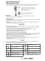
Agilent U1583A Current Clamp
Operating Instructions
The U1583A current clamp is a dual range (40 A and 400 A) clamp-on AC current clamp. This U1583A current
clamp is designed for Agilent handheld digital multimeters (DMM) and Agilent handheld oscilloscopes.
Assistance
For technical assistance, contact your nearest Agilent Sales Offi ce or visit the Agilent website at
www.agilent.com/fi nd/assist for further information.
Safety Information
Please use the Agilent U1583A current clamp only as specifi ed in this manual. Otherwise, the protection provided
may be impaired. Refer to the safety information below.
A WARNING identifi es conditions and actions that pose hazards to the user. A CAUTION identifi es conditions
and actions that may be damaging to the equipment under test.
WARNING
To avoid possible electric shock, personal injury or damage to this instrument, ensure that you use the adapter
safely, and follow these guidelines:
- Do not use the adapter if it is damaged. Inspect the case before you use the adapter. Look for cracks or missing
plastic. Pay particular attention to the insulation surrounding the connectors.
- Inspect the clamp jaw before each use. It shall not have cracks or missing parts, loose or weakened
components. Be sure there is insulation surrounding the jaw.
- Inspect output cable without exposing the metal to ensure insulation.
- Do not operate the adapter around explosive gas, vapor or dust.
- Do not exceed the rated voltage/ current as marked on the adapter.
- This current clamp is designed to be used on INSULATED CONDUCTORS up to 400 A, 600 V CAT III and on BARE
CONDUCTORS of up to 30 VAC rms or 60 VDC. DO NOT USE on BARE CONDUCTORS above 30 VAC rms or
60 VDC. Contact with these voltages will result in electric shock or arc explosion.
- Always keep your hand behind the fi nger guard of clamp jaw.
- When servicing the adapter, use only specifi ed replacement parts.
- Use with caution when working above 30 VAC rms, 42 V peak or 60 VDC. Such voltage poses a shock hazard.
- Avoid working alone.
- Do not operate the adapter if the cover is removed or loosened.
CAUTION
To avoid possible damage to the current clamp or to the equipment under test, follow the guidelines below:
- Do not connect to BNC output or banana plug to any power sources.
- Use the proper terminals, function, and range for your measurements.
AC - Alternating Current Range button in lock mode.
Range ~ 400 A, Output ~ 1 mV/A
Caution, risk of danger (Refer to the user’s
and service guide for details)
DC - Direct Current
400A MAX
Maximum allowable current measurement
is 400 A
Ground
CAT III 600V
Category III 600V over-voltage protection Double Insulation
Range button in release mode.
Range ~ 40 A, Output ~ 10 mV/A
Caution, risk of electric shock (Refer to the
user’s and service guide for detail)
Do not apply around or remove from
HAZARDOUS LIVE conductors
The CE mark is a registered trademark of the
European Community. This CE mark shows that
the product complies with all the relevant
European Legal Directives
The UL mark is a registered trademark of
Underwriters Laboratories Inc.

Introduction
The U1583A current clamp is designed for Agilent handheld digital multimeters (DMM) and handheld
oscilloscopes. The BNC-to-banana plug is required to connect the current clamp with DMM. For handheld
oscilloscope, it needs to use with BNC connector.
Standard Item Purchased Checklist
The following items are included when you make a purchase:
• U1583A current clamp
• BNC-to-banana plug
• Operating Instructions sheet (this sheet)
General Specifi cations
Specifi cations Current Clamp
Specifi ed Current Range 1 A to 400 A ac
Usable Current Range 0.5 A to 400 A
AC crest factor < 3
Bandwidth 10 kHz
Operating Temperature –10 °C to 55 °C (14 °F to 131 °F)
Storage Temperature –20 °C to 70 °C (–4 °F to 158 °F)
Relative Humidity Max 80% RH for temperature up to 35 °C decreasing linearly to 50% RH at 55 °C
Maximum Jaw Opening 32 mm
Maximum conductor size 30 mm or 16 mm x 2
Load impedance > 1 M ohm, < 100 pF
Cable length 1500 +/- 20 mm
Altitude Up to 2000 meters
Safety IEC 61010-1: 2001/EN 61010-1: 2001
IEC 61010-2-032: 2002/EN 61010-2-032: 2002
Canada: CAN/CSA-C22.2 No. 61010-1-04, CAN/CSA-C22.2 No. 61010-2-032-04
USA: ANSI/UL 61010-1: 2004/UL 61010-2-032
Measurement Category CAT III 600 V; Pollution degree 2
EMC Standard
IEC 61326: 2002/EN 61326: 1997+A1: 1998+A2: 2003
Complied to CISPR 11: 1990/EN 55011: 1990 [radiated emission], and equivalents for
Group 1, Class A
Dimensions (HxWxD) 44 mm (H) x 92 mm (W) x 188 mm (L)
Weight 294 grams
Warm-up time Immediately upon power on
Warranty One year
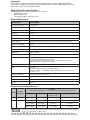
Electrical Accuracy Specifi cations
Range
Output
Resolution
Accuracy
± (% of reading + digit) at 23 °C ± 5 °C, with relative humidity less than 80% R.H.
Span 48 Hz ~ 65 Hz 40 ~ 48 Hz/
65 Hz ~ 1 kHz
1 kHz ~ 10 kHz
40 A 10 mV/A 0.5 A ~ 40 A 2% + 0.5 A 5% + 0.5 A 10% + 0.5 A
400 A 1 mV/A 0.5 A ~ 40 A 2.5% + 0.5 A 4.5% + 0.5 A 12.5% + 0.5 A
40 A ~ 200 A 2% + 0.5 A 4% + 0.5 A 12% + 0.5 A
200 A ~ 400 A 1.5% + 0.5 A 3.5% + 0.5 A 11.5% + 0.5 A
• The current conductor must be centered within the jaw aperture and no infl uence from adjacent currents.
• Connect to load impedance > 1 MW ||100 pF.
• Crest factor < 3.
2

Figure 1: Connection Diagram
Alignment Marks
Put one conductor within the jaws inside the section of the indicated marks as much as possible in order to meet
the accuracy of specifi cations. Make sure the clamp is perpendicular to the conductor.
Current Range Selection
To push and release the yellow button for 40 A range and lock the button for 400 A range.
Button Range Output
Release ~ 40 A ~ 10 mV/A
Lock ~ 400 A ~ 1 mV/A
This current clamp is designed to be used on INSULATED CONDUCTORS up to 400 A,
600 V CAT III and on BARE CONDUCTORS of up to 30 VAC rms or 60 VDC. DO NOT USE
on BARE CONDUCTORS above 30 VAC rms or 60 VDC. Contact with these voltages may
result in electric shock or arc explosion.
Operation
AC current can be measured without removing the conductor from the circuit by following the procedures as
shown below:
1. Plug the cable with BNC connector to the BNC with dual banana plugs, and then plug into the V/COM
terminals on the multimeter. For oscilloscope, plug the BNC connector directly to oscilloscope.
2. Set the ACV measurement and range on multimeter you used.
3. Position the jaw to a single conductor and center it accordingly to the alignment marks.
4. Ensure that the arrow marked on the clamp jaw point towards the load for phase measurements or away
from the load (toward the source) for neutral measurements.
5. Observe the AC value on the multimeter or the waveform on the oscilloscope which is proportional to the
current.
6. Select a lower range on the clamp-on adapter and set the corresponding sensitivity (mV/A setting) on the
oscilloscope if required.
Calibration Equipment
The pre-calibration guidelines are shown as follows:
• Be sure you are a qualifi ed person to perform the calibration
• The environment should be 23 °C ± 2 °C and the relative humidity (RH) shall be < 80%.
The test equipment requirements listed in the table below are required to perform the calibration and performance
verifi cation test procedures. Alternative equipment may be used as long as the accuracy is equivalent to or better
than the specifi cations listed.
Standard Source Operating Range
Accuracy
Required
Recommended
Equipment
AC Current Calibrator 33 mA – 329.99 mA at 10 Hz to 3 kHz
0.33 A – 2.99999 A at 10 Hz to 3 kHz
3 A – 20.5 A at 10 Hz to 3 kHz
≤ ± 0.2%
≤ ± 0.6%
≤ ± 3.0%
Wavetek 9100 or Fluke 5520A or 5101B
or equivalent
Multimeter AC 500.0 mV or 1000.0 mV
≤ ± 1.5%
Agilent U1251A or U1252A or
Agilent-34405A or equivalent
50 Turns Current Coil 0.2 A – 20.5 A
≤ ± 1.0%
Fluke 5500A Coil or Wavetek 9100 Option
200 or equivalent
3
Current
Clamp
BNC-to-
Handheld
Current
Clamp
Handheld
MARK
MARKMARK
CONDUCTOR

Adjustment Procedures
AC 40 A range
1. Release RANGE button of U1583A current clamp to 40 A mode.
2. Connect the output BNC of U1583A to a BNC-to-dual banana converter plug and proceed to
connect it to the output of the V (HI) and COM (LO) terminals of the multimeter.
3. Set multimeter to AC 500.0 mV or 1000.0 mV.
4. Open the jaws of the current clamp and centrally place it around the 50 turns coil.
5. Set the calibrator output to 50 turns coil. Confi gure the calibrator to generate a current 20 A with
60 Hz frequency for adjustment of the current clamp.
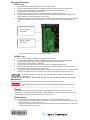
6. Remove two Phillips screws on the back of the current clamp and proceed to adjust the VR1 until the
display on multimeter indicates AC 200 mV ± 0.2 mV. Refer to Figure 2 below for the position of
VR1.
Figure 2: U1583A Current Clamp Circuit Board Diagram
AC 400 A range
1. Lock the Range button of U1583A current clamp to 400 A mode.
2. Connect the output BNC of U1583A to a BNC-to-dual banana converter plug and proceed to
connect it to the output of the V (HI) and COM (LO) terminals of the multimeter.
3. Set multimeter to AC 500.0 mV or 1000.0 mV.
4. Open the jaws of the current clamp and centrally place it around the 50 turns coil.
5. Set the calibrator output to 50 turns coil. Confi gure the calibrator to generate a current 20 A with
60 Hz frequency for adjustment of the current clamp.
6. Remove two Phillips screws on the back of the current clamp and proceed to adjust the VR2 until the
display on multimeter indicates AC 200 mV ± 0.2 mV. Refer to Figure 2 for the position of VR2.
Remember to place the screws to its original position after performing the calibration
adjustments.
Maintenance
Repair or service not cover in this sheet should be performed only by qualifi ed personnel.
To avoid electrical shock or damaged to the clamp-on adapter, do not get water inside the
case .
Cleaning
• Periodically wipe the case with a damp cloth and mild detergent. Do not use abrasive or solvents.
• Open the jaws and wipe the metal of jaw with a lightly oiled cloth, and then wipe the oil with dry cloth.
Do not allow rust or corrosion to form on the metal ends of jaw.
Troubleshooting
If the current clamp does not perform properly, follow the steps below to identify the problem:
1. Inspect the mating surface of jaw for cleanliness. If any external material is present, the jaws may
not close properly and affects the result.
2. Verify that the function selection and range on the multimeter or oscilloscope as well as the range
adjusted on current clamp is correct.
Print Date: 05 January 2008
VR1 for AC 40A
adjustment
VR2 for AC 400A
adjustment
U1583-90100
-
 1
1
-
 2
2
-
 3
3
-
 4
4


Agilent Technologies U1583A Operating instructions
- Type
- Operating instructions
Ask a question and I''ll find the answer in the document
Finding information in a document is now easier with AI
Related papers
-
Agilent Technologies 34450A User manual
-
Agilent Technologies U1231A User manual
-
Agilent Technologies 54621D User manual
-
-
-
-
-
Agilent Technologies 34970A User manual
Other documents
-
 Commercial Electric OTG-102R Operating instructions
-
Fluke Pinza amperometrica CA i1000s User manual
-
-
Tektronix TCP0020 User manual
-
-
Fluke Calibration 5520A Getting Started
-
Fluke 80i-110s User manual
-
Tektronix TCPA300 User manual
-
Extech Instruments CA200 User manual
-
