Page is loading ...

FT-RTM Arc Flash SRL
User Instrucon Manual
MSRD27 Rev A 051023
FallTech 1306 S. Alameda Street Compton, CA 90221, USA Tel: 800-719-4619 Fax: 323-752-5613
This manual is intended to meet the Manufacturer’s Instrucons as required by the American Naonal Standards
Instute (ANSI) Z359 and should be used as part of an employee training program as required by the Occupaonal
Safety and Health Administraon (OSHA).

Table of Contents
1.0 Warnings and Important Informaon ..................................................................................
2.0 Descripon ..........................................................................................................................
3.0 Applicaon ...........................................................................................................................
4.0 System Requirements ..........................................................................................................
5.0 Installaon and Use .............................................................................................................
6.0 Maintenance, Service and Storage ......................................................................................
7.0 Inspecon ............................................................................................................................
8.0 Labels ...................................................................................................................................
9.0 Denions ...........................................................................................................................
Appendix A .........................................................................................................................
3
4
6
6
8
13
14
16
17
19
For purposes of this manual, the FT-RTM Arc Flash SRL in all iteraons may be referred to collecvely as the FT-R, the Arc Flash SRL , the FT-R Arc
Flash, the SRL, the self-retracng device (SRD), the equipment, the device, the product, or the unit.
Throughout this manual, ANSI Z359.0-2012 fall protecon words, phases and terms are used. These terms are all formally dened in Secon 9 of
this manual.
MSRD27 Rev A 051023 2

1.0 Warnings and Important Informaon
This product is part of a personal fall arrest, restraint, work posioning, suspension, or rescue system. A Personal Fall Arrest System (PFAS) is
typically composed of an anchorage and a Full Body Harness (FBH), with a connecng device, i.e., a Energy Absorbing Lanyard (EAL), or a
Self-Retracng Device (SRD), aached to the dorsal D-ring of the FBH.
These instrucons must be provided to the worker using this equipment. The worker must read and understand the manufacturer’s instrucons for
each component or part of the complete system. Manufacturer’s instrucons must be followed for proper use, care, and maintenance of this
product. These instrucons must be retained and be kept available for the worker’s reference at all mes. Alteraons or misuse of this product, or
failure to follow instrucons, may result in serious injury or death.
A Fall Protecon Plan must be on le and available for review by all workers. It is the responsibility of the worker and the purchaser of this
equipment to assure that users of this equipment are properly trained in its use, maintenance, and storage. Training must be repeated at regular
intervals. Training must not subject the trainee to fall hazards.
Consult a doctor if there is reason to doubt your tness to safely absorb the shock of a fall event. Age and tness seriously aect a worker’s ability
to withstand falls. Pregnant women or minors must not use this equipment.
ANSI limits the weight of fall protecon equipment users to a maximum of 310 lbs. Products in this manual may have a rated capacity exceeding
ANSI capacity limits. Heavy users experience more risk of serious injury or death due to falls because of increased fall arrest forces placed on the
user’s body. In addion, the onset of suspension trauma aer a fall even may be accelerated for heavy users.
The user of the equipment discussed in this manual must read and understand the enre manual before beginning work.
NOTE: For more informaon consult the ANSI Z359 or CSA Z259 body of standards.
• Avoid moving machinery, thermal, electrical and/or chemical hazards as contact may cause serious injury or death.
• Avoid swing falls.
• Follow the weight restricons and recommendaons in this manual.
• Remove from service any equipment subjected to fall arrest forces.
• Remove from service any equipment that fails inspecon.
• Do not alter or intenonally misuse this equipment.
• Consult FallTech when using this equipment in combinaon with components or subsystems other than those described in this manual.
• Do not connect rebar hooks, large carabiners, or large snap hooks to the FBH dorsal D-rings as this may cause a roll-out condion and/or
unintenonal disengagement.
• Avoid sharp and/or abrasive surfaces and edges.
• Use cauon when performing arc welding. Arc ash from arc welding operaons, including accidental arcs from electrical equipment, can
damage equipment and are potenally fatal.
• Examine the work area. Be aware of the surroundings and workplace hazards that may impact safety, security, and the funconing of fall arrest
systems and components.
• Hazards may include but not be limited to cable or debris tripping hazards, equipment failures, personnel mistakes, moving equipment such as
carts, barrows, fork lis, cranes, or dollies. Do not allow materials, tools or equipment in transit to contact any part of the fall arrest system.
• Do not work under suspended loads.
WARNING
IMPORTANT
MSRD27 Rev A 051023 3

2.0 Descripon
The FallTech® FT-RTM Arc Flash is a self-retracng device for those working at height and when may be subject to fall hazards. This product is not
suitable for applicaons with leading edge exposures where the lifeline of this device may come in contact with an edge during a fall event. Contact
FallTech for more informaon or product selecon quesons.
This manual contains one Appendix that contains gures and tables specic to the FT-R Arc Flash SRL discussed in this manual.
The SRD discussed in this manual may be aached to an overhead anchorage, i.e., from directly over the user’s head, to as low as the level of the
user’s FBH dorsal D-ring.
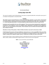
As shown in Figure 1 below, the SRD has a glass reinforced nylon housing with an integrated handle that contains a lifeline composed of 1/4” (7mm)
diameter Technora® synthec rope, wound onto a spring tensioned drum. The SRD’s lifeline is equipped with a lifeline stop/handle assembly with a
bumper, integrated tearaway Energy Absorber (EA), and a leg-end connector. When the user is aached, the lifeline extends and retracts with user
movement, automacally maintaining a taut lifeline. If a fall occurs, a centrifugal pawl system engages, stopping the lifeline payout. The tearaway
EA deploys, gradually slowing and arresng the fall.
See Table 1A in Appendix A for product and materials specicaons.
1
2
3
4
5
6
7
Figure 1 - About FallTech® FT-R Arc Flash SRL
1Anchorage Connecng Carabiner
2Carrying Handle (Not an Anchor)
3Technora® Rope Synthec Lifeline
4Lifeline Stop/Handle Assembly
5Swaged Eye
6Energy Absorber
7Leg-end Connector
MSRD27 Rev A 051023 4

2.1 American Naonal Standards Instute (ANSI) and Occupaonal Safety and Health Administraon (OSHA): The SRD discussed in this
manual meets the standards of ANSI Z359.14-2021, ANSI A10.32-2012, and Occupaonal Safety and Health Administraon (OSHA)
regulaons 1926.502 and 1910.140. ANSI requires SRDs be classied according to the type of usage the user would be exposed to, and are
tested either as Class 1 or Class 2. Dynamic performance means that the SRD is installed in a tesng drop tower. A test weight is aached
to the SRD and then dropped. Test results are recorded.
Parameters recorded are:
The Arrest Distance is the total vercal distance required to arrest a fall. The Arrest Distance includes the deceleraon distance and the
acvaon distance. The Average Arrest Force is the average of the forces applied to the body and the anchorage by the fall protecon
system. The Maximum Arrest Force is the maximum amount of force that may be applied to the body and the anchorage by the fall
protecon system. In addion to the above tests conducted in ambient condions, the units must be retested for average and peak forces
under certain environmental condions, where the units are cooled, then tested, heated, then tested, or saturated in water and tested
again. Separate units may be used for each test. All test results are recorded.
This test data is then used to establish the basis for fall clearance guidelines published in the user instrucon manual.
Class 1 and 2: Class 1 devices shall be used only on overhead anchorages and shall be subjected to a maximum free fall of 2 feet
(0.6 m) or less. Class 2 devices are intended for applicaons where an overhead anchorage may not be available or feasible and be
subjected to a free fall of no more than 6 feet (1.8 m) over an edge.
To be declared a Class 1 and Class 2 device, ANSI requires an SRD to have an overhead Arrest Distance of less than 42” (1.1 m), an Average
Arrest Force of less than 1,350 lbs (6 kN) [1,575 lbs (7 kN) condioned] and a Maximum Arresng Force of 1,800 lbs (8 kN), for both
ambient and condioned tesng.
When dynamically tested in accordance with requirements of ANSI Z359.14-2021, FallTech Class 1 and Class 2 Self-Retracng Devices have
an AAF of 1,350 lbs (6 KN) or less and an AD of less than 42” (1.1 m).
Please see Secon 5 of this user instrucon manual for how to calculate your Minimum Required Fall Clearance (MRFC).
• Arrest Distance (AD)
• Average Arrest Force (AAF)
• Maximum Arrest Force (MAF)
MSRD27 Rev A 051023 5
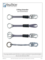
AOverhead Anchorage
BSelf-Retracng Lifeline
CLine Constuent
DSRD Connecon to FBH
EWalking/Working Surface
Figure 2 - Overhead Anchorage

3.0 Applicaon
3.1 Purpose: The FallTech FT-R Arc Flash SRL is designed to be used as a component in a Personal Fall Arrest System (PFAS), to
provide a combinaon of worker mobility and fall protecon as required for inspecon work, general construcon, maintenance work, oil
producon, conned space work, etc. The SRL is intended for Personal Fall Arrest applicaons only.
3.2 Personal Fall Arrest System: A PFAS is an assembly of components and subsystems used to arrest a person during a fall event. A PFAS
typically consists of an anchorage, a deceleraon device such as a Shock Absorbing Lanyard (SAL), a Self-Retracng Device (SRD), or a Fall
Arrestor Connecng Subsystem (FACSS), and a properly ed Full Body Harness (FBH). Maximum permissible free fall in a typical PFAS
is 6’ (1.8 m). The SRD discussed in this manual are intended for overhead use.
3.3 Horizontal Lifeline (HLL) and Rail Systems: The SRD may be aached to rigid and exible anchors provided that all HLL or rail system
applicaons, installaon, and uses are under the supervision of a Qualied Person.
3.4 Rescue: Ensure a wrien rescue plan, method and system is in place and readily available for rapid response. Rescues may require
specialized equipment or measures. Rescue operaons are beyond the scope of this manual. See ANSI Z359.4 and Z359.2.
3.5 Applicaon Limits: Take acon to avoid moving machinery, sharp edges, abrasive surfaces, and thermal, electrical, including the arc from
welding applicaons, and chemical hazards as contact may cause serious injury or death. The SRD is not designed for use in restraint,
personnel riding, suspension, or work posioning. Rescue applicaons are beyond the scope of this manual. Do not use the SRD for these
applicaons except as a back-up PFAS. The SRD discussed in this manual is not designed for Leading Edge applicaons.
4.0 System Requirements
4.1 Capacity: The SRD is designed for use by a single user with a combined weight of user, tools, clothing, etc., of 130–310 lbs (59-141 kg).
4.2 Compability of Connectors: Connectors are considered to be compable with connecng elements when they have been designed to
work together in such a way that their sizes and shapes do not cause their gate mechanisms to inadvertently open regardless of how
they become oriented. Contact FallTech if you have any quesons about compability. Connectors must be compable with the
anchorage or other system components. Do not use equipment that is not compable. Non-compable connectors may unintenonally
disengage. Connectors must be compable in size, shape, and strength. Self-closing, self-locking connectors are required by ANSI and
OSHA.
4.3 Compability of Components: Equipment is designed for use with approved components and subsystems only. Substuons or
replacements made with non-approved components or subsystems may jeopardize compability of equipment and may aect the safety
and reliability of the complete system.
4.4 Making Connecons: Only use self-locking connectors with this equipment. Only use connectors that are suitable to each applicaon.
Ensure all connecons are compable in size, shape, and strength. Do not use equipment that is not compable, see Figure 3.
Visually ensure all connectors are fully closed and locked. Connectors are designed to be used only as specied in each product’s user’s
instrucons.
MSRD27 Rev A 051023 6
ANever connect two acve components (snap hooks or carabiners) to each other.
BNever connect two acve components (snap hooks or carabiners) to a single D-ring at the same me.
CNever connect in a way that would produce a condion of loading on the gate.
DNever aach to a object in a manner whereby the gate (of the snap hook or carabiner) would be
prevented from fully closing and locking. Always guard against false connecons by visually inspecng for closure and lock.
ENever aach explicitly to a constuent subcomponent (webbing, cable or rope) unless specically provided for by the manufacturer’s instrucons for both
subcomponents (snap hook or carabiner and webbing, cable or rope).
FNever aach in a manner where an element of the connector (gate or release lever) may become caught on the anchor thereby producing addional risk of
false engagement.
GNever aach a spreader snap hook to two side/posioning D-rings in a manner whereby the D-rings will engage the gates; the gates on a spreader must
always be facing away from the D-rings during work posioning.
Figure 3 - Non-Compable Connecons

MSRD27 Rev A 051023 7
4.5 Personal Fall Arrest System: PFAS components used in conjuncon with this SRD should comply with ANSI Z359requirements and
applicable OSHA regulaons.
4.6 PFAS Anchorage Strength: An anchorage selected for PFAS must have a strength able to sustain a stac load applied in the direcon
permied by the PFAS of at least:
a) Two mes the maximum arrest force permied when cercaon exists, or
b) 5,000 lbs. (22.2 kN) in the absence of cercaon.
Table 1B in Appendix A provides test data on typical performance aributes of the three principal parameters (see Secon 2.1) for
FallTech self-retracng devices, listed by model number in class. In certain situaons, the qualied person can determine that a given
structure is a suitable anchor point based on a tested arrest distance and tested maximum arrest force, with a safety factor of two.
The Competent Person may nd this data useful when planning anchorage locaon and calculang fall arrest loads and distances from the
walking/working level to the nearest obstrucon or lower level. Select an anchorage locaon carefully. Consider structural strength,
obstrucons in the fall path, and swing fall hazards. See Secon 5.
5.0 Installaon and Use
WARNING
Do not alter or intenonally misuse this equipment. Consult FallTech when using this equipment in combinaon with components or
subsystems other than those described in this manual. All components or subsystems used with the SRD discussed in this manual must be in
compliance with ANSI Z359 and/or OSHA.
Do not use rebar hooks, large carabiners or large snap hooks to connect to the FBH dorsal D-rings or to any small diameter non-compable
anchor point as this may cause a roll-out condion and/or unintenonal disengagement.
Do not insert extra connectors between the SRD lifeline connector and the FBH dorsal D-ring, except an approved D-ring extender.
Use cauon. Take acon to avoid sharp and/or abrasive surfaces and edges.
5.1 Install the SRD: Examine the work area for possible hazards. Take cauon to avoid overhead hazards such as cranes, poles, overhead
power cables, and walking/working surface hazards such as power cables, welding leads, air and uid hoses, including obstrucon hazards
such as vercal columns and stacks of materials on the lower level. Eliminate hazards where possible.
Ensure the anchorage provides the Minimum Required Fall Clearance (MRFC) in the fall path below the walking/working surface to
prevent striking the lower level or an obstrucon during a fall event. Take acon to avoid swing falls, which occur when the anchorage is
not directly above the point where the fall occurs.
Fall clearance and swing falls are subject to variable condions. Anchor height, lateral movement, and setback distance all aect anchor
locaon with regard to fall clearance and swing fall.
The SRD may be aached to an overhead anchor, i.e. above the user’s FBH dorsal D-ring. The SRD discussed in this manual is not
designed for use with a non-overhead anchor, i.e., below the user’s FBH dorsal D-ring. The SRD discussed in the manual is not designed
for leading edge applicaons.

5.2 Calculang Minimum Required Fall Clearance
5.2.1 FT-R Arc Flash in Overhead, Non-Leading Edge Anchorage Applicaon
The FT-R may be used may be used as a standard SRD in an overhead
condion, in which the SRD is installed anywhere in the allowable aachment
area, which ranges from directly above the user to level with the FBH D-ring, as
shown in Figure 4.
The overhead condion minimum required fall clearance (MRFC) is
calculated using four metrics, measured from the walking-working surface:
SRD Deceleraon Distance, D-Ring Shi and Harness Stretch [1 (0.3m)],
Safety Factor [1.5 (0.5m)], and Swing Fall. Chart 1 below is calculated using
the performance data of the SRD and includes all four metrics listed previously
to determine the MRFC.
X-Set -Back
Distance
Y-Lateral Oset Dist.
Z- Minimum Required
Fall Clearance From
Working Surface
20. 5
28.0
X-SRD Anchorage Height
Above Dorsal D-ring
Z- Minimum Required
Fall Clearance From
Working Surface
Y- Lateral
Oset Distance
Figure 4 - MRFC Overhead Anchorage
0
(0 m)
2
(0.7 m)
4
(1.3 m)
6
(1.9 m)
8
(2.5 m)
10
(3.1 m)
12
(3.7 m)
14
(4.3 m)
16
(4.9 m)
18
(5.5 m)
20
(6.1 m)
22
(6.8 m)
24
(7.4 m)
60
(18.3 m)
6.0
(1.9)
6.5
(1.9)
6.5
(1.9)
6.5
(2.0)
7.0
(2.0)
7.0
(2.1)
7.5
(2.2)
8.0
(2.4)
8.5
(2.5)
9.0
(2.7)
9.5
(2.9)
10.0
(3.1)
11.0
(3.3)
55
(16.8 m)
6.0
(1.9)
6.5
(1.9)
6.5
(1.9)
6.5
(2.0)
7.0
(2.1)
7.0
(2.2)
7.5
(2.3)
8.0
(2.4)
8.5
(2.6)
9.0
(2.8)
10.0
(3.0)
10.5
(3.2)
11.5
(3.4)
50
(15.3 m)
6.0
(1.9)
6.5
(1.9)
6.5
(1.9)
6.5
(2.0)
7.0
(2.1)
7.0
(2.2)
7.5
(2.3)
8.0
(2.5)
8.5
(2.6)
9.5
(2.8)
10.0
(3.1)
11.0
(3.3)
11.5
(3.5)
45
(13.8 m)
6.0
(1.9)
6.5
(1.9)
6.5
(1.9)
6.5
(2.0)
7.0
(2.1)
7.5
(2.2)
8.0
(2.4)
8.5
(2.5)
9.0
(2.7)
9.5
(2.9)
10.5
(3.2)
11.5
(3.4)
12.0
(3.7)
40
(12.2 m)
6.0
(1.9)
6.5
(1.9)
6.5
(1.9)
6.5
(2.0)
7.0
(2.1)
7.5
(2.3)
8.0
(2.4)
8.5
(2.6)
9.5
(2.8)
10.0
(3.1)
11.0
(3.3)
12.0
(3.6)
13.0
(3.9)
35
(10.7 m)
6.0
(1.9)
6.5
(1.9)
6.5
(1.9)
7.0
(2.0)
7.0
(2.2)
7.5
(2.3)
8.0
(2.5)
9.0
(2.7)
9.5
(2.9)
10.5
(3.2)
11.5
(3.5)
12.5
(3.8)
13.5
(4.1)
30
(9.2 m)
6.0
(1.9)
6.5
(1.9)
6.5
(2.0)
7.0
(2.1)
7.5
(2.2)
8.0
(2.4)
8.5
(2.6)
9.5
(2.8)
10.0
(3.1)
11.0
(3.4)
12.5
(3.7)
13.5
(4.1)
14.5
(4.4)
25
(7.7 m)
6.0
(1.9)
6.5
(1.9)
6.5
(2.0)
7.0
(2.1)
7.5
(2.3)
8.0
(2.5)
9.0
(2.7)
10.0
(3.0)
11.0
(3.3)
12.0
(3.6)
13.5
(4.0)
14.5
(4.4)
16.0
(4.8)
20
(6.1 m)
6.0
(1.9)
6.5
(1.9)
6.5
(2.0)
7.0
(2.1)
8.0
(2.3)
8.5
(2.6)
9.5
(2.9)
10.5
(3.2)
12.0
(3.6)
13.0
(4.0)
14.5
(4.4)
16.0
(4.8)
17.5
(5.3)
15
(4.6 m)
6.0
(1.9)
6.5
(1.9)
7.0
(2.0)
7.5
(2.2)
8.0
(2.5)
9.5
(2.9)
10.5
(3.2)
12.0
(3.6)
13.0
(4.0)
14.5
(4.4)
16.0
(4.9)
18.0
(5.4)
19.5
(5.9)
10
(3.1 m)
6.0
(1.9)
6.5
(1.9)
7.0
(2.1)
8.0
(2.4)
9.0
(2.7)
10.5
(3.1)
12.0
(3.6)
13.5
(4.1)
15.0
(4.6)
17.0
(5.1)
18.5
(5.6)
20.5
(6.2)
22.0
(6.8)
5
(1.6 m)
6.0
(1.9)
6.5
(1.9)
7.5
(2.3)
9.0
(2.7)
10.5
(3.1)
12.5
(3.6)
14.0
(4.1)
16.0
(4.6)
18.0
(5.5)
20.0
(6.0)
22.0
(6.6)
24.0
(7.2)
26.0
(7.8)
0
(0 m)
6.0
(1.9)
8.0
(2.5)
10.0
(3.1)
12.0
(3.7)
14.0
(4.3)
16.0
(4.9)
18.0
(5.5)
20.0
(6.1)
22.0
(6.8)
24.0
(7.4)
26.0
(8.0)
28.0
(8.6)
30.0
(9.2)
SRD Anchorage Height Above Dorsal D-Ring (X)
Lateral Oset Distance (Y)
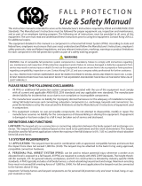
Chart 1
Overhead
Using Chart 1 to Calculate Minimum Required Fall Clearance for the FT-R
2 foot (0.6 m) increments along the Y-Axis represent the Lateral
Oset Distance the user is working away from being directly
under the SRD
5 foot (1.5 m) increments up the X-Axis represent the
SRD Anchorage Height above the user’s Dorsal D-Ring
Example:
If the user needs to work 10 feet (3.1 m) away from directly under the SRD, the SRD needs to be anchored at least 15 feet (4.6 m) above
the user’s Dorsal D-Ring. Minimum required fall clearance is 9.5 feet (2.9 m) at maximum allowable swing fall.
Example:
If the only suitable Anchorage for the SRD is at D-Ring height [0.0 feet (0.0 m)] above the user’s Dorsal D-Ring, the maximum allowable
work zone is 4 feet (1.3 m) away from the SRD. Minimum required fall clearance is 10.0 feet (3.1m) at maximum allowable swing fall.
Key to Work Zone Areas:
= Allowable Use Area = Not Allowed Use Area
WORKING IN THIS AREA MAY RESULT IN SERIOUS INJURY OR DEATH
MSRD27 Rev A 051023 8

5.3 Operaon of the SRD: Before each use, inspect the SRD, see Secon 7 for inspecon instrucons.
5.3.1 Locking Mechanism: The SRD ulizes an acceleraon based locking mechanism. The locking funcon requires a certain payout rate during
a fall event to funcon correctly. Certain situaons, conned or cramped spaces, shiing foong such as sand, gravel, grain, or a sloped
surface may not allow the lifeline to reach sucient speed to acvate the lock mechanism. A clear path is required to assure posive
locking of the SRD. Ensure the lock is funconing properly. Pull the lifeline out a short distance and give it a sharp tug. The lifeline must
lock. If it fails to lock, remove it from service immediately. Ensure the work zone remains within stated parameters. Beware of
Leading Edge hazards.
DO NOT aach an addional shock absorbing lanyard or similar device between the SRD housing and the anchorage.
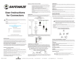
5.3.2 Fall Arrest Impact Indicator: The primary fall arrest impact indicator is the load-indicang Energy Absorber. The Energy Absorber will
display a red and white band if it has been subjected to fall arrest, or equal, forces, as shown in Figure 13, Image B. If the Energy Absorber
shows any sign of damage, torn or ripped cover, frayed thread, burns or trauma of any kind, remove the unit from service.
TM
TM
412-06297 Rev A
OK
DEPLOYED
DANGER
Figure 13 - Inspecng SRD Load-Indicang Energy Absorber
BA
SAFE
TO
USE
REMOVE
FROM
SERVICE
MSRD27 Rev A 051023 9

5.3.3 Inspect the Lifeline: The SRD lifeline is Technora rope, and subject to certain hazards. Inspect the lifeline before each use for the
condions as described in Secon 7.
5.7 Using the SRD: Do not use the SRD if inspecon shows damage or any malfuncon. Don the FBH in accordance with the FBH
manufacturer’s instrucons. Follow the instrucons contained in this manual and on the labels. Failure to follow instrucons may result
in serious injury or death. Connect the leg end carabiner to the dorsal D-ring on the FBH. Ensure the carabiner closes and locks. Aach the
housing carabiner to the chosen anchorage and ensure the carabiner closes and locks. Ensure all connecons are compable.
Normal operaon will allow the working length of the lifeline to extend and retract as the worker moves about. A certain amount of
tension must remain on the lifeline at all mes to ensure proper operaon of the internal brake. Do not allow the lifeline to become slack.
If the lifeline becomes slack, remove the SRD from service for inspecon. See Secon 7.
Avoid sudden or quick movements during the normal work operaon, as this may cause the SRD brake to engage and possibly cause loss
of balance and injury or death.
If a fall occurs, the brake will engage and lock the lifeline. The EA will deploy to arrest the fall and limit arrest forces on the user.
• DO NOT extend the lifeline past the operaonal limit.
• DO NOT allow one SRD lifeline to become tangled or twisted with another SRD lifeline during use.
• DO NOT allow any lifeline to pass under arms or between legs during use.
• DO NOT clamp, knot, or prevent the lifeline from retracng or being taut.
• DO NOT lengthen the SRD by connecng a lifeline or similar component.
• DO NOT allow the lifeline to remain outside the housing when not in use.
• DO NOT allow the lifeline to freewheel back into the housing. Use a tag line to maintain tension and rewind the
lifeline during periods of inacvity. Use the tag line to retrieve the leg end connector for the next use.
• DO NOT leave the tag line connected to the leg end connector when using the SRD for fall protecon.
5.8 Aer A Fall: A fall event over an edge may require special rescue equipment and measures. Ensure a wrien rescue plan, method and
system is in place and readily available to all users for rapid response. Ensure all users are trained in rescue procedures. If a fall event
occurs, remove it from service, and store it separately. Remove from service any unit that has been subjected to fall arrest forces or that
exhibits damage consistent with such forces. For quesons, contact FallTech.
6.0 Maintenance, Service and Storage
6.1 Maintenance: Ensure the SRD is kept free of excess paint, grease, dirt or other contaminants as this may cause to cable or retracng
mechanism to malfuncon. Ensure no debris enters the housing through the lifeline access port. Clean the exterior of the unit as required
with a detergent/water soluon. Avoid water other corrosion causing elements to enter the housing. Aer cleaning, pull the lifeline
all the way out, allow the unit to air dry, then retract the lifeline into the unit. Do not allow the lifeline to freewheel back into the
housing. Clean labels as required.
DO NOT use heat to dry.
DO NOT aempt to disassemble the SRD.
6.2 Service: If service is required for any reason; inspecon failure, impact loaded, any type of malfuncon, tag the unit as “UNUSABLE”, store
separately, and contact FallTech at 800-719-4619 to receive a Return Authorizaon number or to locate the nearest FallTech Service
Center. The SRD is not user repairable. Only the manufacturer, or a repair facility authorized in wring, may make repairs to the SRD.
This SRD is designed to be used installed in an anchor cradle or aached overhead. While it may be used horizontally on a at surface, the
user may encounter a situaon where the lifeline will not retract all the way due to misalignment and bunching up on the drum.
If this happens, hang the SRD from a height sucient to allow the full working length of the lifeline to be pulled o the drum, then allow
the SRD to retract the lifeline completely. Maintain tension on the lifeline. Use a tag line if necessary.
6.3 Storage: Hang the SRD in a cool, dry, clean environment out of direct sunlight. Posion the SRD so excess water can drain out. Avoid expo
sure to chemical or causc vapors. Thoroughly inspect the SRD aer any period of extended storage.
MSRD27 Rev A 051023 10

Inspecon Pass Fail
The rope lifeline should extract and retract completely and without faltering and should remain taut under tension without sagging.
Extract the rope lifeline several inches and apply a rm pull to conrm the SRD locks. The locking should be certain and without
skidding. Repeat this lockup at addional places along the lifeline length to conrm the SRD is operang correctly.
Examine the load indicator on the Energy Absorber to be certain that it has not been loaded, impacted or acvated. (see Figure 13 if
needed)
Inspect the enre length of the constuent lifeline. Review the rope lifeline closely for abrasion damage, glazing, secons of variable
or decreased lifeline thickness, kinking, or hockling. Also examine for dirt, paint, grease, or oil. Check for damage caused by chemical
corrupon or excessive heat as evident with discoloraon. See Figure 14 for examples. If any of these condions exist, remove the
SRD from service.
Check for any missing or loose screws or nuts and any deformed or damaged components.
Examine the external housing for cracks, breaks or warping.
Check the external Connector Eye and the Anchorage Carabiner for damage and deformaon. The Anchorage Carabiner Gate should
open and snap shut easily and smoothly.
Examine the overall SRD unit for any indicaons of deterioraon or damage.
All labels must be intact and totally legible (see Secon 8).
Table 1 - Guidelines for Cable SRD Inspecon
7.0 Inspecon
7.1 Pre-Use User Inspecon: Perform an inspecon before each use in accordance with the recommendaons in Table 1 below.
7.2 Inspecon Frequency: Inspecon by a competent person at regular intervals is required. The competent person will use the informaon
in Table 2: SRD Inspecon Recommendaons, to determine the inspecon frequency. Use Table 2 to determine the inspecon frequency.
Inspecon by a factory authorized inspecon enty at regular intervals is also required.
Table 2 - SRD Inspecon Frequency Recommendaons
Type of Use Applicaon Examples Condions of Use Inspecon Frequency
Competent Person
Infrequent to
Light Use
Rescue and Conned
Space, Factory
Maintenance
Good Storage Condions,
Indoor or Infrequent
Outdoor use, Room
Temperature, Clean
Environments
Annually
Moderate to
Heavy Use
Transportaon,
Residenal
Construcon, Ulies,
Warehouse
Fair Storage Condions,
Indoor and extended
outdoor use, All
temperatures, Clean or
dusty
environments
Semi-annually to
Annually
Severe to
Connuous Use
Commercial
Construcon, Oil and Gas,
Mining
Harsh Storage Condions,
Prolonged or Connuous
outdoor Use, all
temperatures, Dirty
environments
Quarterly to
Semi-annually
MSRD27 Rev A 051023 11

7.3 Inspecon Checklist: Use Table 1: Guidelines for Cable SRD Inspecon to inspect the SRD. See Figure 14 for examples of cable damage.
7.4 Inspecon Results: If an inspecon reveals defects in or damage to the equipment, inadequate maintenance or acvated fall indicators,
remove the equipment from service.
7.5 Inspecon Document: Record inspecon results on the Inspecon Record provided below or on a similar document.
Inspecon Record
Model #:_________________________ Serial #:_________________________ Date of Manufacture:_________________________
INSPECTION
DATE INSPECTOR COMMENTS PASS/FAIL CORRECTIVE ACTION NEEDED APPROVED BY
MSRD27 Rev A 051023 12

8.0 Labels
8.1 Labels: The labels must be present and legible.
MSRD27 Rev A 051023 13

9.0 Denions
The following are general denions of fall protecon terms as dened by ANSI Z359.0-2012.
Anchorage -A secure connecng point or a terminang component of a fall protecon system or rescue system capable of safely supporng the
impact forces applied by a fall protecon system or anchorage subsystem.
Anchorage Connector - A component or subsystem that funcons as an interface between the anchorage and a fall protecon, work posioning,
rope access or rescue system for the purpose of coupling the system to the anchorage.
Arrest Distance - The total vercal distance required to arrest a fall. The arrest distance includes the deceleraon distance and acvaon distance.
Authorized Person – A person assigned by the employer to perform dues at a locaon where the person will be exposed to a fall hazard.
Available Clearance - The distance from a reference point, such as the working plaorm, to the nearest obstrucon that an authorized person might
contact during a fall which, if struck, could cause injury.
Capacity - The maximum weight that a component, system or subsystem is designed to hold.
Cercaon - The act of aesng in wring that the criteria established by these standards or some other designated standard have been met.
Cered Anchorage - An anchorage for fall arrest, posioning, restraint or rescue systems that a qualied person ceres to be capable of support-
ing the potenal fall forces that could be encountered during a fall.
Clearance - The distance from a specied reference point, such as the working plaorm or anchorage of a fall arrest system, to the lower level that a
worker might encounter during a fall.
Clearance Requirement - The distance below an authorized person that must remain clear of obstrucons in order to ensure that the authorized
person does not make contact with any objects that would cause injury in the event of a fall.
Competent Person - An individual designated by the employer to be responsible for the immediate supervision, implementaon and monitoring of
the employer’s managed fall protecon program who, through training and knowledge, is capable of idenfying, evaluang and addressing exisng
and potenal fall hazards, and who has the employer’s authority to take prompt correcve acon with regard to such hazards.
Component - An element or integral assembly of interconnected elements intended to perform one funcon in the system.
Connecng Subsystem - An assembly, including the necessary connectors, comprised of all components, subsystems, or both, between the anchor-
age or anchorage connector and the harness aachment point.
Connector - A component or element that is used to couple parts of the system together.
Deceleraon Distance - The vercal distance between the user’s fall arrest aachment at the onset of fall arrest forces during a fall, and aer the
fall arrest aachment comes to a complete stop.
Energy (Shock) Absorber - A component whose primary funcon is to dissipate energy and limit deceleraon forces which the system imposes on
the body during fall arrest.
Fall Arrest - The acon or event of stopping a free fall or the instant where the downward free fall has been stopped.
Fall Hazard - Any locaon where a person is exposed to a potenal free fall.
Free Fall -The act of falling before a fall protecon system begins to apply forces to arrest the fall.
Free Fall Distance - The vercal distance traveled during a fall, measured from the onset of a fall from a walking working surface to the point at
which the fall protecon system begins to arrest the fall.
Harness, Full Body - A body support designed to contain the torso and distribute the fall arrest forces over at least the upper thighs, pelvis, chest
and shoulders.
Horizontal Lifeline – A component of a horizontal lifeline subsystem, consisng of a exible line with connectors or other coupling means at both
ends for securing it horizontally between two anchorages or anchorage connectors.
Horizontal Lifeline Subsystem – An assembly, including the necessary connectors, comprised of a horizontal lifeline component and, oponally, of:
a) An energy absorbing component or, b) A lifeline tensioner component, or both. This subsystem is normally aached at each end to an anchorage
or anchorage connector. The end anchorages have the same elevaon.
MSRD27 Rev A 051023 14

Horizontal Lifeline – A component of a horizontal lifeline subsystem, consisng of a exible line with connectors or other coupling means at both
ends for securing it horizontally between two anchorages or anchorage connectors.
Horizontal Lifeline Subsystem – An assembly, including the necessary connectors, comprised of a horizontal lifeline component and, oponally, of:
a) An energy absorbing component or, b) A lifeline tensioner component, or both. This subsystem is normally aached at each end to an anchorage
or anchorage connector. The end anchorages have the same elevaon.
Lanyard - A component consisng of a exible rope, wire rope or strap, which typically has a connector at each end for connecng to the body
support and to a fall arrester, energy absorber, anchorage connector or anchorage.
Lanyard Connecng Subsystem - An assembly, including the necessary connectors, comprised of a lanyard only, or a lanyard and energy absorber.
Personal Fall Arrest System (PFAS) - An assembly of components and subsystems used to arrest a person in a free fall.
Posioning - The act of supporng the body with a posioning system for the purpose of working with hands free.
Posioning Lanyard - A lanyard used to transfer forces from a body support to an anchorage or anchorage connector in a posioning system.
Qualied Person - A person with a recognized degree or professional cercate and with extensive knowledge, training and experience in the fall
protecon and rescue eld who is capable of designing, analyzing, evaluang and specifying fall protecon and rescue systems.
Self-Retracng Device (SRD) - A device that contains a drum wound line that automacally locks at the onset of a fall to arrest the user, but that
pays out from and automacally retracts onto the drum during normal movement of the person to whom the line is aached.
Snaphook - A connector comprised of a hook-shaped body with a normally closed gate or similar arrangement that may be opened to permit the
hook to receive an object and, when released, automacally closes to retain the object.
Swing Fall - A pendulum-like moon that occurs during and/or aer a vercal fall. A swing fall results when an authorized person begins a fall from a
posion that is located horizontally away from a xed anchorage.
MSRD27 Rev A 051023 15

APPENDIX A
Table 1A: Specicaons for FT-R Arc Flash SRL
Model # Lifeline Material
Working Length,
Weight, and Housing
Size
Materials and
Specicaons
Capacity and
Standards SRL
721530T
721530TD1
1/4” (7mm)
Diameter
Technora Rope
30 (9.1 m)
15.0 lbs (6.8 kg)
10” X 10”
(254 mm X 254 mm)
Housing:
Glass Reinforced
Nylon
Anchorage Carabiner:
5,000 lbs (22.2 kN)
with 3,600 lbs (16 kN)
Gate Strength
Swivel Snap Hook:
5,000 lbs (22.2 kN)
with 3,600 lbs (16 kN)
Gate Strength
Single User Capacity:
130 to 310 lbs.
(59 to 141 kg)
ANSI Z359.14-2021
Class 1
OSHA 1926.502
OSHA 1910.66
ASTM F887-20*
Table 1B: FallTech FT-R Arc Flash Class 1 Edge SRL ANSI Performance Aributes
Part #s and Condions Typical FallTech Performance ANSI Performance Requirements
Part # Anchorage
Condion
Arrest
Distance
Average
Arrest Force
Maximum
Arrest Force
Maximum
Arrest
Distance
Average
Arrest Force
*Condioned
Maximum
Arrest Force
721530T
721530TD1
Overhead
Non-Leading
Edge
42”
(1.1 m)
1,178 lbf
(5.2 kN)
1,601 lbf
(7.1 kN)
42”
(1.1 m)
1,575 lbf
(7.0 kN)
1,800 lbf
(8.0kN)
MSRD27 Rev A 051023 16
/