Notifier UniNet 2000 AFP-300 Fire Alarm Control Panel User manual
- Category
- Fire protection
- Type
- User manual

UniNet™ 2000
AFP-300/400 NION Plug-In
Instruction Manual
AFP-300/400 NION
Document 51996
03/04/03 Rev A1
Version 2
51996:A1 ECN 03-04751996:A1 ECN 03-047
51996:A1 ECN 03-04751996:A1 ECN 03-047
51996:A1 ECN 03-047
www.PDF-Zoo.com
firealarmresources.com

2
Document 51996 AFP-300/400 NION Installation Rev. A1 03/04/03
www.PDF-Zoo.com
firealarmresources.com

3
Document 51996 AFP-300/400 NION Installation Rev. A1 03/04/03
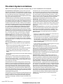
An automatic fire alarm system–typically made up of smoke
detectors, heat detectors, manual pull stations, audible warning
devices, and a fire alarm control with remote notification capabil-
ity–can provide early warning of a developing fire. Such a sys-
tem, however, does not assure protection against property dam-
age or loss of life resulting from a fire.
The Manufacturer recommends that smoke and/or heat detec-
tors be located throughout a protected premise following the rec-
ommendations of the current edition of the National Fire Protec-
tion Association Standard 72 (NFPA 72), manufacturer's recom-
mendations, State and local codes, and the recommendations
contained in the Guide for Proper Use of System Smoke Detec-
tors, which is made available at no charge to all installing deal-
ers. A study by the Federal Emergency Management Agency
(an agency of the United States government) indicated that
smoke detectors may not go off in as many as 35% of all fires.
While fire alarm systems are designed to provide early warning
against fire, they do not guarantee warning or protection against
fire. A fire alarm system may not provide timely or adequate
warning, or simply may not function, for a variety of reasons:
Smoke detectors may not sense fire where smoke cannot
reach the detectors such as in chimneys, in or behind walls, on
roofs, or on the other side of closed doors. Smoke detectors
also may not sense a fire on another level or floor of a building.
A second-floor detector, for example, may not sense a first-floor
or basement fire.
Particles of combustion or "smoke" from a developing fire
may not reach the sensing chambers of smoke detectors be-
cause:
• Barriers such as closed or partially closed doors, walls, or
chimneys may inhibit particle or smoke flow.
• Smoke particles may become "cold," stratify, and not reach
the ceiling or upper walls where detectors are located.
• Smoke particles may be blown away from detectors by air
outlets.
• Smoke particles may be drawn into air returns before reaching
the detector.
The amount of "smoke" present may be insufficient to alarm
smoke detectors. Smoke detectors are designed to alarm at
various levels of smoke density. If such density levels are not
created by a developing fire at the location of detectors, the de-
tectors will not go into alarm.
Smoke detectors, even when working properly, have sensing
limitations. Detectors that have photoelectronic sensing cham-
bers tend to detect smoldering fires better than flaming fires,
which have little visible smoke. Detectors that have ionizing-
type sensing chambers tend to detect fast-flaming fires better
than smoldering fires. Because fires develop in different ways
and are often unpredictable in their growth, neither type of detec-
tor is necessarily best and a given type of detector may not pro-
vide adequate warning of a fire.
Smoke detectors cannot be expected to provide adequate warn-
ing of fires caused by arson, children playing with matches (es-
pecially in bedrooms), smoking in bed, and violent explosions
(caused by escaping gas, improper storage of flammable mate-
rials, etc.).
Heat detectors do not sense particles of combustion and alarm
only when heat on their sensors increases at a predetermined
rate or reaches a predetermined level. Rate-of-rise heat detec-
tors may be subject to reduced sensitivity over time. For this
reason, the rate-of-rise feature of each detector should be tested
at least once per year by a qualified fire protection specialist.
Heat detectors are designed to protect property, not life.
IMPORTANT! Smoke detectors must be installed in the same
room as the control panel and in rooms used by the system for
the connection of alarm transmission wiring, communications,
signaling, and/or power. If detectors are not so located, a devel-
oping fire may damage the alarm system, crippling its ability to
report a fire.
Audible warning devices such as bells may not alert people if
these devices are located on the other side of closed or partly
open doors or are located on another floor of a building. Any
warning device may fail to alert people with a disability or those
who have recently consumed drugs, alcohol or medication.
Please note that:
• Strobes can, under certain circumstances, cause seizures in
people with conditions such as epilepsy.
• Studies have shown that certain people, even when they hear
a fire alarm signal, do not respond or comprehend the mean-
ing of the signal. It is the property owner's responsibility to
conduct fire drills and other training exercise to make people
aware of fire alarm signals and instruct them on the proper
reaction to alarm signals.
• In rare instances, the sounding of a warning device can cause
temporary or permanent hearing loss.
A fire alarm system will not operate without any electrical
power. If AC power fails, the system will operate from standby
batteries only for a specified time and only if the batteries have
been properly maintained and replaced regularly.
Equipment used in the system may not be technically compat-
ible with the control. It is essential to use only equipment listed
for service with your control panel.
Telephone lines needed to transmit alarm signals from a
premise to a central monitoring station may be out of service or
temporarily disabled. For added protection against telephone line
failure, backup radio transmission systems are recommended.
The most common cause of fire alarm malfunction is inade-
quate maintenance. To keep the entire fire alarm system in ex-
cellent working order, ongoing maintenance is required per the
manufacturer's recommendations, and UL and NFPA standards.
At a minimum, the requirements of Chapter 7 of NFPA 72 shall
be followed. Environments with large amounts of dust, dirt or
high air velocity require more frequent maintenance. A mainte-
nance agreement should be arranged through the local
manufacturer's representative. Maintenance should be sched-
uled monthly or as required by National and/or local fire codes
and should be performed by authorized professional fire alarm
installers only. Adequate written records of all inspections
should be kept.
Fire Alarm System Limitations
While a fire alarm system may lower insurance rates, it is not a substitute for fire insurance!
Precau-L-4-2002.p65
www.PDF-Zoo.com
firealarmresources.com

4
Document 51996 AFP-300/400 NION Installation Rev. A1 03/04/03
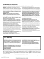
WARNING - Several different sources of power can be con-
nected to the fire alarm control panel. Disconnect all sources of
power before servicing. Control unit and associated equipment
may be damaged by removing and/or inserting cards, modules,
or interconnecting cables while the unit is energized. Do not
attempt to install, service, or operate this unit until this manual is
read and understood.
CAUTION - System Reacceptance Test after Software
Changes. To ensure proper system operation, this product
must be tested in accordance with NFPA 72 Chapter 7 after any
programming operation or change in site-specific software. Re-
acceptance testing is required after any change, addition or de-
letion of system components, or after any modification, repair or
adjustment to system hardware or wiring.
All components, circuits, system operations, or software func-
tions known to be affected by a change must be 100% tested. In
addition, to ensure that other operations are not inadvertently
affected, at least 10% of initiating devices that are not directly
affected by the change, up to a maximum of 50 devices, must
also be tested and proper system operation verified.
This system meets NFPA requirements for operation at
0-49° C/32-120° F and at a relative humidity of 85% RH - 93%
per ULC - (non-condensing) at 30° C/86° F. However, the useful
life of the system's standby batteries and the electronic compo-
nents may be adversely affected by extreme temperature ranges
and humidity. Therefore, it is recommended that this system
and all peripherals be installed in an environment with a nominal
room temperature of 15-27° C/60-80° F.
Verify that wire sizes are adequate for all initiating and
indicating device loops. Most devices cannot tolerate more than
a 10% I.R. drop from the specified device voltage.
Like all solid state electronic devices, this system may
operate erratically or can be damaged when subjected to light-
ning-induced transients. Although no system is completely im-
mune from lightning transients and interferences, proper ground-
ing will reduce susceptibility. Overhead or outside aerial wiring
is not recommended, due to an increased susceptibility to
nearby lightning strikes. Consult with the Technical Services
Department if any problems are anticipated or encountered.
Disconnect AC power and batteries prior to removing or in-
serting circuit boards. Failure to do so can damage circuits.
Remove all electronic assemblies prior to any drilling, filing,
reaming, or punching of the enclosure. When possible, make all
cable entries from the sides or rear. Before making modifica-
tions, verify that they will not interfere with battery, transformer,
and printed circuit board location.
Do not tighten screw terminals more than 9 in-lbs.
Over-tightening may damage threads, resulting in reduced
terminal contact pressure and difficulty with screw terminal re-
moval.
Though designed to last many years, system components
can fail at any time. This system contains static-sensitive com-
ponents. Always ground yourself with a proper wrist strap be-
fore handling any circuits so that static charges are removed
from the body. Use static-suppressive packaging
to protect electronic assemblies removed from the unit.
Follow the instructions in the installation, operating, and
programming manuals. These instructions must be followed to
avoid damage to the control panel and associated
equipment. FACP operation and reliability depend upon proper
installation by authorized personnel.
WARNING: This equipment generates, uses, and can radiate
radio frequency energy and if not installed and used in accor-
dance with the instruction manual, may cause interference to
radio communications. It has been tested and found to com-
ply with the limits for class A computing device pursuant to
Subpart B of Part 15 of FCC Rules, which is designed to pro-
vide reasonable protection against such interference when
operated in a commercial environment. Operation of this
equipment in a residential area is likely to cause interference,
in which case the user will be required to correct the interfer-
ence at his own expense.
Canadian Requirements
This digital apparatus does not exceed the Class A
limits for radiation noise emissions from digital
apparatus set out in the Radio Interference Regulations of the
Canadian Department of Communications.
Le present appareil numerique n'emet pas de bruits radio-
electriques depassant les limites applicables aux appareils
numeriques de la classe A prescrites dans le Reglement sur
le brouillage radioelectrique edicte par le ministere des Com-
munications du Canada.
FCC Warning
Installation Precautions
Adherence to the following will aid in problem-free installation with long-term reliability:
Precau-L-4-2002.p65
Acclimate Plus™, HARSH™, NOTI•FIRE•NET™, ONYX™, and VeriFire™ are trademarks, and FlashScan® and VIEW® are registered trademarks of NOTIFIER.
NION™ and UniNet™ are trademarks of NIS. NIS™ and Notifier Integrated Systems™ are trademarks and NOTIFIER® is a registered trademark of Fire•Lite
Alarms, Inc. Echelon® is a registered trademark and LonWorks™ is a trademark of Echelon Corporation. ARCNET® is a registered trademark of Datapoint
Corporation. Microsoft® and Windows® are registered trademarks of the Microsoft Corporation. LEXAN® is a registered trademark of GE Plastics, a subsidiary
of General Electric Company.
www.PDF-Zoo.com
firealarmresources.com

5
Document 51996 AFP-300/400 NION Installation Rev. A1 03/04/03
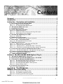
Contents
Foreword .................................................................................................... 7
Introduction ................................................................................................ 7
Section One: Description and Installation .................................................. 9
1.1 Description of the AFP-300/400 NION ............................................................................. 9
FIgure 1-1: NION Architecture Diagram ...................................................................................... 9
Figure 1-2: AFP-300/400 NION Board Layout............................................................................ 10
1.2 AFP-300/400 NION Connectors ...................................................................................... 11
1.3 Installation Description .................................................................................................... 11
1.4 Cabinet Mounting Information ....................................................................................... 11
Figure 1-3: CAB-A3/4 Enclosure .................................................................................................11
Figure 1-4: NION Stand-Alone Enclosure Mounting Hole Layout ............................................... 12
Figure 1-5: ABS-4D/B Annunciator Backbox............................................................................... 12
1.5 AFP-300/400 NION Diagnostic LEDs .............................................................................. 13
Figure 1-6: NION LEDs .............................................................................................................. 13
1.6 NION Power Requirements ............................................................................................. 13
Figure 1-7: AFP-300/400 NION TB5 Power Connection ............................................................. 13
1.7 Relay output - Fault Annunciation .................................................................................. 13
Figure 1-8: AFP-300/400 Fault Annunciation ............................................................................. 13
1.8 SMX Network Connection ................................................................................................ 14
Figure 1-9: SMX Transceivers: FTXC-PCA and FTXC-PCB ........................................................... 15
Figure 1-10: FTXC-PCA Transceiver Wiring ................................................................................. 15
Figure 1-11: SMX Transceivers: S7FTXC-PCA Style 7 Transceiver ................................................ 16
Figure 1-12: FOXC-PCA and DFXC-PCA Fiber Optic Network Transceivers ................................ 16
1.9 Serial Connections with the AFP-300/400 Control Panel .............................................. 17
Figure 1-13: AFP-300/400 NION/AFP - 300/400 Panel Wiring Diagram .................................... 17
1.10 Software Replacement/Upgrade Installation ............................................................... 18
Figure 1-14: NION Software Replacement ................................................................................. 18
1.11 EVENT REPORTING FORMAT .......................................................................................... 19
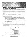
Section 2: The AFP-300/400 NION Explorer Plug-In ................................ 21
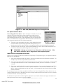
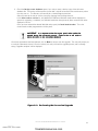
2.1 AFP-300/400 NION Explorer Overview.......................................................................... 21
2.2 Registering the AFP-300/400 NION Explorer with UniNet ............................................ 21
2.3 Launching the AFP-300/400 NION Explorer .................................................................. 21
Figure 2-1: AFP-300/400 NION Explorer Workstation Launch Menu .......................................... 21
Figure 2-2: AFP-300/400 Sample Right-Click Menu.................................................................... 22
Figure 2-3: AFP-300/400 NION Explorer Startup Screen ............................................................ 23
Figure 2-4: Option Pulldown Menu ............................................................................................ 23
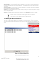
2.4 Viewing the Silenced Panels List...................................................................................... 24
Figure 2-5: Silenced Panels List ................................................................................................... 24
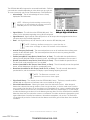
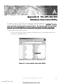
Appendix A: The AFP-300/400................................................................. 25
Database Conversion Utility ..................................................................... 25
Figure A-1: Accessing the Conversion Utility ............................................................................... 25
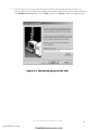
Figure A-2: The Database Upgrade File Path .............................................................................. 26
Figure A-3: Performing the Conversion Upgrade ........................................................................ 27
Index ........................................................................................................ 29
www.PDF-Zoo.com
firealarmresources.com

6
Document 51996 AFP-300/400 NION Installation Rev. A1 03/04/03
Related Documentation
Network Installation M anual 51539 UniLogic 51547
Workstation 51540 Event Manager 51546
System Utilities 51592 UniTour 51550
BCI ver. 3-3 51543 AFP-300/400 Operation Manual 50260
Local Area Server 51544 Wide Area Server 51545
www.PDF-Zoo.com
firealarmresources.com

7
Document 51996 AFP-300/400 NION Installation Rev. A1 03/04/03
Foreword
The contents of this manual are important and must be kept in close proximity of the hardware. If building owner-
ship is changed, this manual and all other testing and maintenance information must also be passed to the current
owner of the facility. A copy of this manual was shipped with the equipment and is also available from the manu-
facturer.
This equipment has been designed to comply with standards set forth by the following regulatory agencies:
NFPA Standards
• National Fire Protection Association Standards 72.
• National Electric Code (NFPA 70).
• Life Safety Code (NFPA 101).
Underwriters Laboratories U.S. Documents
• UL-864 Control Units for Fire Protective Signaling Systems.
• UL-1076 Proprietary Burglar Alarm Units and Systems.
Other
• Requirements of the Local Authority Having Jurisdiction (LAHJ).
WARNING:WARNING:
WARNING:WARNING:
WARNING: Improper installation, maintenance, and lack of routine testing could result in system malfunction.
Introduction
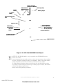
The AFP-300/400 NION is a plug-in component of the UniNet Workstation. It allows a workstation to view events
and other data originating from the AFP-300 or AFP-400 fire alarm control panels.
UniNet consists of graphical workstations monitoring and controlling local or remote twisted pair or fiber optic
networks. Remote network monitoring is achieved through the use of a Building Communications Interface (BCI),
which has a maximum capacity of 32 nodes. Each Local Area Server (LAS) has a maximum capacity of 200
nodes, using twisted pair or fiber-optic cabling. A twisted pair network topology (FT-10) may be a maximum length
of 6000 feet per network segment with no T-taps, allowing communications between 64 nodes in each segment.
In addition, FT-10 allows dedicated runs of 8000 feet point-to-point or multiple T-taps within 1500 feet of any
other node on the segment. Fiber-optic cable runs can be configured in either a bus or ring topology. The
network is supervised for shorts, opens and node failures as dictated in Style 4 wiring.
The network power is 24 VDC nominal and receives operating power from a power limited, filtered source listed for
use with fire protective signaling units.
www.PDF-Zoo.com
firealarmresources.com

8
Document 51996 AFP-300/400 NION Installation Rev. A1 03/04/03
This page intentionally left blank.
www.PDF-Zoo.com
firealarmresources.com

9
Document 51996 AFP-300/400 NION Installation Rev. A1 03/04/03
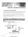
1.1 Description of the AFP-300/400 NION
The AFP-300/400 NION (Network Input Output Node) is the EIA-232 interface used with the network. All of the
system components are based on LonWorks™ (Local Operating Network) technologies. The AFP-300/400 NION
provides transparent or interpreted communications between the Workstation and control panels. Unless otherwise
noted, full control capabilities are available for each interface. Check specific connections for details.
The NION connects a LonWorks™ FT-10 or fiber optic network, and the EIA-232 port of control panels. It
provides a two-way communication channel for EIA-232 serial data when connected to a control panel. NIONs
are specific to the type of network to which they connect (FT-10 or fiber). The LonWorks™ network interface
accepts any standard SMX style transceiver (FTXC, S7FTXC, FOXC, or DFXC). The transceiver type must be
specified and ordered separately when ordering the NION.
The NION mounts in an enclosure (NISCAB-1 or CHS-4L in CAB-3 or CAB-4 series enclosure - sold separately)
with conduit knockout.
WW
WW
Workstationorkstation
orkstationorkstation
orkstation
Local Area ServerLocal Area Server
Local Area ServerLocal Area Server
Local Area Server
AFPAFP
AFPAFP
AFP-300/400 NION-300/400 NION
-300/400 NION-300/400 NION
-300/400 NION
(AFP(AFP
(AFP(AFP
(AFP-300/400 NION)-300/400 NION)
-300/400 NION)-300/400 NION)
-300/400 NION)
NONO
NONO
NOTETE
TETE
TE: The NION is installed in the: The NION is installed in the
: The NION is installed in the: The NION is installed in the
: The NION is installed in the
cabinet with the AFPcabinet with the AFP
cabinet with the AFPcabinet with the AFP
cabinet with the AFP-300/400 F-300/400 F
-300/400 F-300/400 F
-300/400 FAA
AA
ACP*)CP*)
CP*)CP*)
CP*)
AFPAFP
AFPAFP
AFP-300/400 F-300/400 F
-300/400 F-300/400 F
-300/400 FAA
AA
ACP*CP*
CP*CP*
CP*
*FACP: Fire Alarm Control Panel
NOTE: This NION is only compatible with UniNet
2.0 and later Workstation software.
When upgrading from the older AFPWhen upgrading from the older AFP
When upgrading from the older AFPWhen upgrading from the older AFP
When upgrading from the older AFP-300/400 NION-232B board, the database conversion utility-300/400 NION-232B board, the database conversion utility
-300/400 NION-232B board, the database conversion utility-300/400 NION-232B board, the database conversion utility
-300/400 NION-232B board, the database conversion utility
needs to be run before installing the new AFPneeds to be run before installing the new AFP
needs to be run before installing the new AFPneeds to be run before installing the new AFP
needs to be run before installing the new AFP-300/400 NION board. The conversion utility will-300/400 NION board. The conversion utility will
-300/400 NION board. The conversion utility will-300/400 NION board. The conversion utility will
-300/400 NION board. The conversion utility will
alter existing device IDs in the screen database to match the new format used by this NIONalter existing device IDs in the screen database to match the new format used by this NION
alter existing device IDs in the screen database to match the new format used by this NIONalter existing device IDs in the screen database to match the new format used by this NION
alter existing device IDs in the screen database to match the new format used by this NION. Any. Any
. Any. Any
. Any
UniLUniL
UniLUniL
UniLogic equations from the old system must be recreated after installing the new AFPogic equations from the old system must be recreated after installing the new AFP
ogic equations from the old system must be recreated after installing the new AFPogic equations from the old system must be recreated after installing the new AFP
ogic equations from the old system must be recreated after installing the new AFP-300/400-300/400
-300/400-300/400
-300/400
NIONNION
NIONNION
NION..
..
.
See Appendix A for details on the conversion utilitySee Appendix A for details on the conversion utility
See Appendix A for details on the conversion utilitySee Appendix A for details on the conversion utility
See Appendix A for details on the conversion utility..
..
.
Section One: Description and Installation
1
FIgure 1-1: NION Architecture Diagram
www.PDF-Zoo.com
firealarmresources.com

10
Document 51996 AFP-300/400 NION Installation Rev. A1 03/04/03
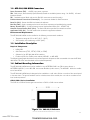
Figure 1-2: AFP-300/400 NION Board Layout
3V Lithium3V Lithium
3V Lithium3V Lithium
3V Lithium
BatteryBattery
BatteryBattery
Battery
J1 Header for EchelonJ1 Header for Echelon
J1 Header for EchelonJ1 Header for Echelon
J1 Header for Echelon
Network TNetwork T
Network TNetwork T
Network Transceiverransceiver
ransceiverransceiver
ransceiver
Application PLCCApplication PLCC
Application PLCCApplication PLCC
Application PLCC
SW2 NetworkSW2 Network
SW2 NetworkSW2 Network
SW2 Network
Binding ButtonBinding Button
Binding ButtonBinding Button
Binding Button
SW1 ResetSW1 Reset
SW1 ResetSW1 Reset
SW1 Reset
ButtonButton
ButtonButton
Button
Network CommunicationNetwork Communication
Network CommunicationNetwork Communication
Network Communication
PLCCPLCC
PLCCPLCC
PLCC
SMX TSMX T
SMX TSMX T
SMX Transceiverransceiver
ransceiverransceiver
ransceiver
Standoff MountingStandoff Mounting
Standoff MountingStandoff Mounting
Standoff Mounting
HolesHoles
HolesHoles
Holes
ChassisChassis
ChassisChassis
Chassis
GroundGround
GroundGround
Ground
{
Diagnostic LEDSDiagnostic LEDS
Diagnostic LEDSDiagnostic LEDS
Diagnostic LEDS
R72 Cut TR72 Cut T
R72 Cut TR72 Cut T
R72 Cut To Disableo Disable
o Disableo Disable
o Disable
Ground Fault DetectionGround Fault Detection
Ground Fault DetectionGround Fault Detection
Ground Fault Detection
GND +24VDC
PP
PP
Power Input (TB5)ower Input (TB5)
ower Input (TB5)ower Input (TB5)
ower Input (TB5)
P2 Serial Interface BP2 Serial Interface B
P2 Serial Interface BP2 Serial Interface B
P2 Serial Interface B
NUP PNUP P
NUP PNUP P
NUP Port (EIAort (EIA
ort (EIAort (EIA
ort (EIA-232)-232)
-232)-232)
-232)
TB6-Relay OutputTB6-Relay Output
TB6-Relay OutputTB6-Relay Output
TB6-Relay Output
U24U24
U24U24
U24
BT1BT1
BT1BT1
BT1
U6U6
U6U6
U6
TB1-Serial Interface ATB1-Serial Interface A
TB1-Serial Interface ATB1-Serial Interface A
TB1-Serial Interface A
P1 Serial Interface AP1 Serial Interface A
P1 Serial Interface AP1 Serial Interface A
P1 Serial Interface A
NUP PNUP P
NUP PNUP P
NUP Port (EIAort (EIA
ort (EIAort (EIA
ort (EIA-232)-232)
-232)-232)
-232)
NOTES: The AFP-300/400 NION is only compatible with AFP-300/400 firmware
version 3.6 or later.
It is recommended that the installer conform to local code requirements when installing
all wiring. All power connections must be non-resettable. Refer to the current Notifier
catalog for specific part numbers and ordering information for each NION.
To avoid damage to hardware, always remove power from the NION before making
any changes to switch settings and removing or installing option modules, SMX network
modules and software upgrade chips.
Always observe ESD protection procedures.
J1J1
J1J1
J1
www.PDF-Zoo.com
firealarmresources.com

11
Document 51996 AFP-300/400 NION Installation Rev. A1 03/04/03
1.2 AFP-300/400 NION Connectors
Power Connector (TB5) - +24VDC input power connector.
TB6 - Relay output; both Normally Open/Normally Closed are available (contact rating: 2A 30VDC). All rated
loads are resistive.
TB1 - Standard terminal block style port for EIA-232 connection to serial channel A.
Echelon Network Transceiver Connector(J1) - Pin connection header for SMX Transceiver.
Reset Pin (SW1) - Resets the NION and restarts the software.
Bind Pin (SW2) - Sends a message to the Local Area Server requesting to be added to the network.
Battery Terminal (BT1) - 3V Lithium battery terminal (replacement battery P/N - LITHBATT-3V).
Network Communication PLCC (U24) - The flash module that specifies the network transceiver.
Application PLCC (U6) - The flash module that contains the application software.
Environmental Requirements
The AFP-300/400 NION can be installed in the following environmental conditions:
• Temperature range of 0ºC to 49ºC (32°F - 120°F).
• 93% humidity non-condensing at 30ºC (86°F).
1.4 Cabinet Mounting Information
The AFP-300/400 NION board can be installed in any NOTIFIER® CAB-3 or CAB-4 series cabinet, a
NOTIFIER® NISCAB-1, or an ABS-4DB Annunciator Backbox (surface mount). The NISCAB-1 allows the installa-
tion of one NION.
The AFP-300/400 NION board is designed to be installed on a wall within 20 feet in conduit of the control panel
in the same room. The type of hardware used is at the discretion of the installer, but it must be in accordance with
local code requirements.
CAB-3/CAB-4 Series Installation
The CHS-4L or CHS-M2 chassis gets mounted into a CAB-3 or CAB-4 series cabinet.
Figure 1-3: CAB-A3/4 Enclosure
1.3 Installation Description
Required Components
• NION-SPB
• SMX Transceiver (FTXC, S7FTXC, FOXC, or DFXC)
• Software kit for AFP-300/400 NION interface
• Enclosure (CAB-3 or CAB-4 series cabinet, NISCAB-1, or ABS-4DB)
The following paragraphs describe all required and optional components used to assemble a functional AFP-300/
400 NION. All of the items described must be ordered separately.
www.PDF-Zoo.com
firealarmresources.com

12
Document 51996 AFP-300/400 NION Installation Rev. A1 03/04/03
NISCAB-1 Installation
The AFP-300/400 NION may be mounted stand-alone in a single node enclosure, the NISCAB-1, where power is
supplied by the monitored equipment or an external source. This enclosure is provided with door and key lock.
Mounting the enclosure to its wall position
1) Use the provided key to unlock the enclosure cover.
2) Remove the enclosure cover.
3) Mount the enclosure to the wall. Refer to the enclosure mounting hole layout below.
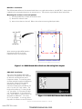
Figure 1-4: NION Stand-Alone Enclosure Mounting Hole Layout
When mounting single NION boards in
this enclosure, be sure to use the
inboard set of four mounting studs.
ABS-4D/B Installation
The Annunciator Backbox (ABS-4D/B)
cabinet has a hinged door with a key lock
(to diminish unauthorized use) and a
transparent window. The mounting panel
and door are both hinged at the bottom for
easy access. Power must be supplied
externally if the cabinet is surface
mounted. Knockouts are provided for use
with a 1/2-inch (12.7mm) conduit. The
height of the cabinet is 12 inches (30.48
cm), the width is 19-7/8 inches (50.483
cm), and the depth is 3-1/2 inches (8.9
mm). If the cabinet is a surface mount, the
door adds an additional 1-1/4 inches
(31.75) to the depth. A trim ring will be
required if the cabinet is a semi-flush mount.
Figure 1-5: ABS-4D/B Annunciator Backbox
www.PDF-Zoo.com
firealarmresources.com

13
Document 51996 AFP-300/400 NION Installation Rev. A1 03/04/03
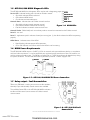
1.7 Relay output - Fault Annunciation
TB6 on the SPB board is used to annunciate a trouble condition;
Normally Open and Normally Closed contacts are available.
The red Relay Power LED on the AFP-300/400 NION indicates a
trouble with either serial communication or Echelon network
communication.
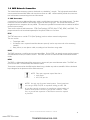
1.5 AFP-300/400 NION Diagnostic LEDs
The AFP-300/400 NION has 6 diagnostic LEDs used as aids in diagnosing proper operation.
Service LED - Indicates binding status of node on Echelon network.
• Slow blink indicates NION not bound.
• Off indicates NION bound.
• On indicates nonrecoverable error.
Network Status - Indicates status of Echelon network interface.
• Slow blink indicates network operation normal.
• Off indicates network interface not functioning.
• Fast blink indicates a network communication error.
Network Packet - Blinks briefly each time a data packet is received or transmitted on the Echelon network.
Serial 2 - not used.
Serial 1 - Application specific indicator of serial port activity (port 1); slow blink indicates the NION is operating
properly.
NION Status - Indicates status of the NION.
• Rapid blinking indicates proper NION operation.
• On or Off indicates critical error and that the NION is not functioning.
1.6 NION Power Requirements
The AFP-300/400 NION requires +24VDC @ 250 mA nominal and supervised battery backup in accordance
with local code requirements. It can be powered by any regulated, power limited source that is UL listed for use
with fire protective signaling units. The NION is equipped with a +3VDC lithium battery for data backup during
low power conditions. The AFP-300/400 NION is powered by external +24VDC supply at TB5.
Figure 1-7: AFP-300/400 NION TB5 Power Connection
(-) Ground(-) Ground
(-) Ground(-) Ground
(-) Ground (+) 24VDC(+) 24VDC
(+) 24VDC(+) 24VDC
(+) 24VDC
TB5TB5
TB5TB5
TB5
TB6TB6
TB6TB6
TB6
Figure 1-6: NION LEDs
ServiceService
ServiceService
Service
Network StatusNetwork Status
Network StatusNetwork Status
Network Status
Network PNetwork P
Network PNetwork P
Network Packetacket
acketacket
acket
Serial 2Serial 2
Serial 2Serial 2
Serial 2
Serial 1Serial 1
Serial 1Serial 1
Serial 1
NION StatusNION Status
NION StatusNION Status
NION Status
Figure 1-8: AFP-300/400 Fault
Annunciation
www.PDF-Zoo.com
firealarmresources.com

14
Document 51996 AFP-300/400 NION Installation Rev. A1 03/04/03
1.8 SMX Network Connection
The UniNet facilities monitoring system is distributed via a LonWorks™ network. This high-speed network allows
communication between field nodes and a Local Area Server or a BCI. NION modules provide the communica-
tion links between monitored equipment and the network.
J1 SMX Connection
A twisted pair of wires or dedicated fiber-optic cable is used for data transmission in the UniNet network. The SMX
transceiver connects the NION to the network using one of these wiring types. The network SMX transceiver
daughter board is a component of every NION. This transceiver provides the network medium interface for NION
network communication.
There are four styles of SMX transceivers: FTXC (Free Topology), S7FTXC (Style 7 FTXC), DFXC, and FOXC. The
proper transceiver must be ordered separately for the specific medium it is to utilize.
FTXC
The FTXC transceiver is used for FT-10 (Free Topology) wire bus and star network configurations.
The wire must be:
• Twisted pair cable.
• UL listed for use in a power-limited fire-detection system (if used in conjunction with a fire monitoring
network).
• Riser, plenum, or non-plenum cable, according to local fire alarm wiring codes.
FOXC
The FOXC transceiver is used for point-to-point optical fiber. For the FOXC, two strands are required per segment;
one dedicated to transmit, the other to receive. The FOXC can have no more than 8db of attenuation between
nodes.
DFXC
The DFXC is a bidirectional optical fiber transceiver; it requires only one strand between nodes. The DFXC can
have no more than 12.5db of attenuation between nodes.
Transceivers are mounted to the NION mother board using a header strip and two standoffs. Refer to the board
layout diagram for the placement of the SMX transceivers.
NOTE: Fiber optic segments require fiber that is:
• Multi-mode.
• 62.5/125 µm dia.
NOTES: Use only wire for power limited systems. Power limited wire
runs use type FPLR, FPLP, FPL or equivalent cabling per NEC 760.
All non-fiber network connections are transformer isolated making all
network communication immune to ground fault conditions. There-
fore, no ground fault supervision of the Echelon network is required
or provided.
www.PDF-Zoo.com
firealarmresources.com

15
Document 51996 AFP-300/400 NION Installation Rev. A1 03/04/03
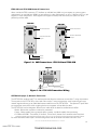
FTXC-PCA and FTXC-PCB Network Transceivers
When used by the FTXC transceiver, FT-10 allows up to 8,000 feet (2438.4 m) per segment in a point-to-point
configuration, up to 6,000 feet (1828.8 m) per segment in a bus configuration, or up to 1,500 feet (457.2 m) per
segment in a star configuration. Each segment can support 64 nodes, and with routers, the system can be ex-
panded up to 200 nodes.
Data A
Data B
Twisted Pair
FTXC-PCAFTXC-PCA
FTXC-PCAFTXC-PCA
FTXC-PCA
Figure 1-10: FTXC-PCA Transceiver Wiring
FTXC-PCBFTXC-PCB
FTXC-PCBFTXC-PCB
FTXC-PCB
FT-10 Transceiver
Header Connection
Electrical Termination
Jumper
Data B
Data A
FTXC-PCAFTXC-PCA
FTXC-PCAFTXC-PCA
FTXC-PCA
FT-10 Transceiver
Header Connection
Electrical Termination
Jumper
Data A
Data B
Figure 1-9: SMX Transceivers: FTXC-PCA and FTXC-PCB
S7FTXC-PCA (Style-7) Network Transceiver
The S7FTXC-PCA combines two FT-10 interface ports that allow the transceiver to meet Style-7 wiring requirements.
The two ports on the S7FTXC-PCA, when used with true style-7 wiring requirements, create a point-to-point type
network segment allowing up to 8,000 feet between nodes that use the S7FTXC-PCA. The seperate FT ports allow
two twisted pair connections so that a cabling fault on one segment will not affect the other.
The S7FTXC-PCA has four diagnostic LEDs that are visible when the board is installed onto a NION.
•Packet - Blinks when a packet is received or transmitted.
• Status - Blinks steadily when no network traffic is present, and blinks rapidly when processing.
• P1 ERR and P2 ERR - These LEDs (P1 for Port1, P2 for Port 2) denote error conditions when they blink.
NOTE: The S7FTXC temporarily stops processing when an error occurs. This suppresses noise propagation throughout the network.
For more information about Style-7 network configuration refer to the Local Area Server manual 51544.
www.PDF-Zoo.com
firealarmresources.com

16
Document 51996 AFP-300/400 NION Installation Rev. A1 03/04/03
Figure 1-11: SMX Transceivers: S7FTXC-PCA Style 7 Transceiver
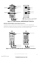
FOXC-PCA and DFXC-PCA Fiber Optic Network Transceivers
The FOXC-PCA allows up to 8db of attenuation between nodes in a point to point configuration only.
The DFXC-PCA can operate in either a bus or a ring format. The regenerative properties of the DFXC transceiver
allow runs of up to 12db of attenuation between each node, with up to 64 nodes per segment.
S7FTXCS7FTXC
S7FTXCS7FTXC
S7FTXC
Style 7 FT-10 Transceiver
Header Connection
Port 1
Port 2
Packet LED
Status LED
Port 1 Error LED
Port 2 Error LED
Opposite side of S7FTXC
Termination Jumper
( Port 2)
Termination Jumper
(Port 1)
Bus Termination
FT Termination
Bus Termination
FT Termination
NOTE: See section 1.1.8 of the Network
Installation manual for more information
about FT and Bus termination.
DFXCDFXC
DFXCDFXC
DFXC
Dual Fiber Optic Transceiver
FOXCFOXC
FOXCFOXC
FOXC
Fiber Optic Transceiver
Header Connection Header Connection
ST Style TX Connection
ST Style RX Connection
ST Style Connection
Figure 1-12: FOXC-PCA and DFXC-PCA Fiber Optic Network Transceivers
www.PDF-Zoo.com
firealarmresources.com

17
Document 51996 AFP-300/400 NION Installation Rev. A1 03/04/03
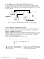
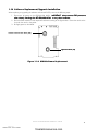
1.9 Serial Connections with the AFP-300/400 Control Panel
The NION must be connected to the CPU-300/400 board of the AFP-300/400 panel. Serial communication
wires must be connected to the TB2 connector (EIA 232). For specific connections, refer to Figure 1-13: AFP-
300/400 NION/AFP-300/400 Wiring Diagram. The NION should be mounted within 20ft of the panel with all
connections run in conduit.
Figure 1-13: AFP-300/400 NION/AFP - 300/400 Panel Wiring Diagram
Powering the NION from the AFP-300/400 Control Panel
The NION should use terminals 3 (+24) and 4 (Common) of the TB2 connector of the MPS-300/400 board to
get the auxiliary power from the AFP-300/400 panel. This power source is power limited and non-resettable. For
specific connections, refer to Figure 1-13: AFP-300/400 NION - AFP-300/400 Panel Wiring Diagram.
Configuring the AFP-300/400 Control Panel
IMPORTANT: The panel must have a network node address programmed in the panel. This node address
is internal to the panel and can be any three digit number. However, it is recommended that the address number
be the same as the NION node number it communicates with. Refer to the AFP-300/400 manual for more
information on programming panel node addresses.
The NION operates at 2400 baud, 8 data bits, no parity, and 1 stop bit.
In order to utilize all features available with the AFP-300/400, the AFP-300/400 Plug-In utility must be configured
at the system Workstations. General Plug-In setup information can be found in the Workstation manual.
AFPAFP
AFPAFP
AFP-300/400-300/400
-300/400-300/400
-300/400
AFPAFP
AFPAFP
AFP-300/400 NION-300/400 NION
-300/400 NION-300/400 NION
-300/400 NION
CPU-300/400CPU-300/400
CPU-300/400CPU-300/400
CPU-300/400
MPSMPS
MPSMPS
MPS-300/400-300/400
-300/400-300/400
-300/400
power supplypower supply
power supplypower supply
power supply
Be sure that if you use AFP-300/400 plug-ins
that you associate them with AFP-300/400
NIONs, respectively.
NOTE: Use only wire for power limited systems.
Power limited wire runs use type FPLR, FPLP, FPL
or equivalent cabling per NEC 760.
RxTxRefRxTxRef
RxTxRefRxTxRef
RxTxRef
TB2TB2
TB2TB2
TB2
Tx Rx RefTx Rx Ref
Tx Rx RefTx Rx Ref
Tx Rx Ref
+-+-+-+-+-+-
+-+-+-+-+-+-
+-+-+-
123456123456
123456123456
123456
++
++
+
--
--
-
TB2TB2
TB2TB2
TB2
TB5TB5
TB5TB5
TB5
TB1TB1
TB1TB1
TB1
NOTE: The AFP-300/400 NION is only
compatible with AFP-300/400 firmware version
3.6 or later.
www.PDF-Zoo.com
firealarmresources.com

18
Document 51996 AFP-300/400 NION Installation Rev. A1 03/04/03
1.10 Software Replacement/Upgrade Installation
When replacing or upgrading the software and network PLCCs, execute the following steps:
1. Disconnect all power to the AFP-300/400 NION. IMPORIMPOR
IMPORIMPOR
IMPORTT
TT
TANTANT
ANTANT
ANT: Always exercise ESD precautions: Always exercise ESD precautions
: Always exercise ESD precautions: Always exercise ESD precautions
: Always exercise ESD precautions
when directly handling the AFPwhen directly handling the AFP
when directly handling the AFPwhen directly handling the AFP
when directly handling the AFP-300/400 NION or any other hardware.-300/400 NION or any other hardware.
-300/400 NION or any other hardware.-300/400 NION or any other hardware.
-300/400 NION or any other hardware.
2. Place the flash modules in their respective sockets according to the figure below. Orient the notch on the
chip with the notch in the socket.
3. Re-apply power to the NION.
Network Communication PLCC (U24)Network Communication PLCC (U24)
Network Communication PLCC (U24)Network Communication PLCC (U24)
Network Communication PLCC (U24)
Application PLCC (U6)Application PLCC (U6)
Application PLCC (U6)Application PLCC (U6)
Application PLCC (U6)
Figure 1-14: NION Software Replacement
www.PDF-Zoo.com
firealarmresources.com

19
Document 51996 AFP-300/400 NION Installation Rev. A1 03/04/03
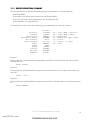
1.11 EVENT REPORTING FORMAT
All Event reporting from the AFP-300/400 NION appears at the Workstation in the following format:
NNNSSSXXXXXXXX
Where NNN is the network node number for the AFP-300/400 NION.
Where SSS is the node number programmed in the AFP-300/400 panel.
Where XXXXXXXX is an 8 digit device ID.
The 8 digit ID will conform to one of the following formats, depending on the nature of the device.
87654321
Detectors: LllDddd Lll = loop, Dddd = detector
Modules: LllMmmm Lll = loop, Mmmm = module
Annunciators: ANNUNaa aa = annunciator
Annunciator Points: AaaPppp aa = annunciator, ppp = point
Bell Circuits: BC cc cc = circuit
Panel Circuits: PC cc-p cc = circuit, p = point
Zones: ZONEzzz zzz = zone
Panel: Panel
Ground: GROUND
Battery: BATTERY
AC Power: ACPOWER
Audibles: Audible
Example 1:
Echelon Node 001, AFP-300/400 Panel programmed as node 007, Loop 02, Detector 003 reports with the
following device ID:
001007 L02D003
Example 2:
Echelon Node 007, AFP-300/400 Panel programmed as node 003, Bell Circuit 01 reports with the following
device ID:
007003 BC 01
Example 3:
Echelon Node 003, AFP-300/400 Panel programmed as node 001, Zone 004 reports with the following device
ID:
003001 ZONE004
www.PDF-Zoo.com
firealarmresources.com

20
Document 51996 AFP-300/400 NION Installation Rev. A1 03/04/03
This page intentionally left blank.
www.PDF-Zoo.com
firealarmresources.com
Page is loading ...
Page is loading ...
Page is loading ...
Page is loading ...
Page is loading ...
Page is loading ...
Page is loading ...
Page is loading ...
Page is loading ...
Page is loading ...
Page is loading ...
Page is loading ...
-
 1
1
-
 2
2
-
 3
3
-
 4
4
-
 5
5
-
 6
6
-
 7
7
-
 8
8
-
 9
9
-
 10
10
-
 11
11
-
 12
12
-
 13
13
-
 14
14
-
 15
15
-
 16
16
-
 17
17
-
 18
18
-
 19
19
-
 20
20
-
 21
21
-
 22
22
-
 23
23
-
 24
24
-
 25
25
-
 26
26
-
 27
27
-
 28
28
-
 29
29
-
 30
30
-
 31
31
-
 32
32


Notifier UniNet 2000 AFP-300 Fire Alarm Control Panel User manual
- Category
- Fire protection
- Type
- User manual
Ask a question and I''ll find the answer in the document
Finding information in a document is now easier with AI
Related papers
-
Notifier UniNet Lite Owner's manual
-
-
-
Notifier AFP-200 User manual
-
-
-
-
-
-
Notifier N-ANN-I/O LED Driver Module Owner's manual
Other documents
-
Honeywell CT50A Standard low volt Thermostat User manual
-
Potter RA-6075R LCD Annunciator Owner's manual
-
YAESU FT-991A User manual
-
 Simplex 4098 True Alarm Analog Addressable Detector Base User manual
-
Mircom RAX-LCD-LITE Remote Annunciator User manual
-
-
-
Siemens DB-X11RS Detector Base User manual
-
-
MGC MIX-4045 Dual Relay Module User manual
